Transcription
RCS-603: COMPUTER GRAPHICSUNIT-IIIPresented By :Dr. Vinod Jain (Associate Professor, GLBITM)
Topics Left 3d Object Representation (chapter 10, 10.1) 3-D Geometric Primitives, (9.1,9.2) 3-D viewing, projections, 3-D Clipping. (ch 12)
3d Object Representation3D object representation is divided into two categories. Boundary Representations (B-reps) It describes a 3D object as a set of surfaces that separates the objectinterior from the environment. Space–partitioning representations It is used to describe interior properties, by partitioning the spatialregion containing an object into a set of small, non-overlapping,contiguous solids (usually cubes).
3d Object Representation :Polygon Surfaces
3d Object Representation :Polygon Surfaces The most commonly used representation for a 3D graphics object. It is a set of surface polygons that enclose the object interior. Set of polygons are stored for object description. This simplifies and speeds up the surface rendering and display ofobject since all surfaces can be described with linear equations.
3d Object Representation :Polygon SurfacesThree ways to represent polygon surfaces1. Polygon Tables2. Plane Equations3. Polygon Meshes
Polygon Tables
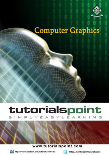
Polygon TablesThe object is store by using three tables1. Vertex Table2. Edge table3. Polygon-Surface table
Polygon Tables- Vertex TableVertex TableIt store x, y, and z coordinate information of all the vertices as v1: x1, y1, z1.
Polygon Tables - Edge tableEdge table The Edge table is used to store the edge information of polygon. In the following figure, edge E1 lies between vertex v1 and v2 which isrepresented in the table as E1: v1, v2.
Polygon Tables - Polygon-Surface tablePolygon-Surface tablePolygon surface table stores the number of surfaces present in thepolygon.From the following figure, surface S1 is covered by edges E1, E2 andE3 which can be represented in the polygon surface table as S1: E1, E2,and E3
Plane Equations The equation for plane surface can be expressed as Ax By Cz D 0 Where (x, y, z) is any point on the plane, and the coefficients A, B, C,and D are constants describing the spatial properties of the plane. We can obtain the values of A, B, C, and D by solving a set of threeplane equations using the coordinate values for three non collinearpoints in the plane. Let us assume that three vertices of the plane are(x1, y1, z1), (x2, y2, z2) and (x3, y3, z3).
Plane Equations The equation for plane surface can be expressed as Ax By Cz D 0 We can obtain the values of A, B, C, and D by solving a set of threeplane equations. Let us assume that three vertices of the plane are (x1, y1, z1), (x2, y2,z2) and (x3, y3, z3).
Plane Equations Let us solve the following simultaneous equations for ratios A/D, B/D,and C/D. You get the values of A, B, C, and D.(A/D) x1 (B/D) y1 (C/D) z1 -1(A/D) x2 (B/D) y2 (C/D) z2 -1(A/D) x3 (B/D) y3 (C/D) z3 -1
Plane Equations
Plane Equations
Polygon Meshes3D surfaces and solids can be approximated by a set of polygonal andline elements. Such surfaces are called polygonal meshes.In polygon mesh, each edge is shared by at most two polygons.The set of polygons or faces, together form the “skin” of the object.
Polygon Meshes Advantages It can be used to model almost any object.They are easy to represent as a collection of vertices.They are easy to transform.They are easy to draw on computer screen. Disadvantages Curved surfaces can only be approximately described. It is difficult to simulate some type of objects like hair or liquid.
Three Dimensional ConceptsThree Dimensional Display Methods: Parallel Projection Perspective Projection Depth Queing Visible Line and Surface Identification Surface Rendering Exploded and Cutaway Views Three-Dimensional and Stereoscopic Views
Three Dimensional ConceptsThree Dimensional Display Methods: To obtain a display of a three dimensional scene that has beenmodeled in world coordinates, we must setup a co-ordinate referencefor the ‘camera’.
Three Dimensional ConceptsThree Dimensional Display Methods: The objects can be displayed inwire frame form, or we can applylighting and surface renderingtechniques to shade the visiblesurfaces.
Parallel Projection Parallel projection is a method for generating a view of a solid objectis to project points on the object surface along parallel lines onto thedisplay plane. This technique is used in engineering and architectural drawings torepresent an object with a set of views that maintain relativeproportions of the object.
Perspective Projection
Perspective Projection It is a method for generating a view of a three dimensional scene is toproject points to the display plane alone converging paths. In a perspective projection, parallel lines in a scene that are notparallel to the display plane are projected into converging lines. Scenes displayed using perspective projections appear more realistic,since this is the way that our eyes and a camera lens form images.
Depth Cueing:
Depth Cueing: Depth cueing is a method for indicating depth with wire framedisplays is to vary the intensity of objects according to their distancefrom the viewing position. Depth cueing is applied by choosing maximum and minimumintensity (or color) values and a range of distance over which theintensities are to vary.
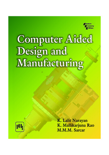
Visible Line and Surface Identification A simplest way to identify the visible line is to highlight the visiblelines or to display them in a different color. Another method is to display the non visible lines as dashed lines.
Visible Line and Surface Identification The wireframe representation of thepyramid in (a) contains no depth information toindicate whether the viewing direction is (b) downward from a position above theapex or (c) upward from a position below the base.
Surface Rendering
Surface Rendering Surface rendering method is used to generate a degree of realism in adisplayed scene. Realism is attained in displays by setting the surface intensity ofobjects according to the lighting conditions in the scene and surfacecharacteristics. Lighting conditions include the intensity and positions of light sourcesand the background illumination. Surface characteristics include degree of transparency and how roughor smooth the surfaces are to be.
Exploded and Cutaway Views Exploded and cutaway views of objects can be to show the internalstructure and relationship of the objects parts. An alternative to exploding an object into its component parts is thecut away view which removes part of the visible surfaces to showinternal structure.
Three-Dimensional and Stereoscopic Views In Stereoscopic views, three dimensional views can be obtained byreflecting a raster image from a vibrating flexible mirror. The vibrations of the mirror are synchronized with the display of thescene on the CRT. Stereoscopic devices present two views of a scene; one for the lefteye and the other for the right eye.
Three-Dimensional and Stereoscopic Views Stereoscopic devices present twoviews of a scene; one for the left eye and the other for the right eye.
3-D Transformation Methods for geometric transformations are extended from twodimensional methods by including considerations for the zcoordinate. We will discuss following transformations in 3D1. Translation2. Rotation3. Scaling4. Reflection5. Shear
Unit- III1.2.3.4.5.6.3-D Geometric Primitives3-D Object representation3-D Transformation3-D viewingprojections3-D Clipping.
3-D Translation
3-D Translation by translation vectorT (tx,ty,tz)
3-D RotationTo generate a rotation transformation for an object, we must designate1. An axis of rotation (about which the object is to be rotated)2. The amount of angular rotation.
3-D Rotation In two-dimensional applications, where all transformations arecarried out in the xy plane A three-dimensional rotation can be specified around any line inspace. The easiest rotation axes to handle are those that are parallel to thecoordinate axes.
3-D Rotation – three rotation axis are
3-D Rotation : In homogeneous coordinatesz-axis rotation equations are expressed as
3-D Rotation : In homogeneous coordinatesz-axis rotation equations are expressed as
3-D Rotation : In homogeneous coordinatesx-axis rotation equations are expressed as
3-D Rotation : In homogeneous coordinatesy-axis rotation equations are expressed as
General Three-Dimensional Rotations(About any given axis)Three Steps1. Translate the object so that the rotation axis coincides with theparallel coordinate axis.2. Perform the specified rotation about that axis.3. Translate the object so that the rotation axis is moved back to itsoriginal position.
General Three-Dimensional Rotations(About any given axis)
3 D SCALING The matrix expression tor thescaling transformation of aposition P (x, y, z) relative tothe coordinate origin can bewritten asP’ S . PWhere Sx, Sy and Sz are scalingfactors along three axis
Scaling with respect to a selected fixedposition (xf, yf, zf)
Scaling with respect to a selected fixedposition (xf, yf, zf) Scaling with respect to a selected fixedposition can be represented with thefollowing transformation sequence:1. Translate the fixed point to the origin.2. Scale the object relative to the coordinateorigin.3. Translate the fixed point back to its originalposition.
Scalingwithrespect toa selectedfixedposition(xf, yf, zf)
Scaling with respect to a selected fixedposition (xf, yf, zf) The matrix representation for an arbitrary fixed-point scaling can thenbe expressed as the concatenation of these translate-scale-translatetransformations as
Other Transformations in 3D Reflection Shear
Reflection in 3D A three-dimensional reflection can be performed relative to aselected reflection axis or with respect to a selected reflection plane. When the reflection plane is a coordinate plane (either xy, xz, or yz),we can think of the transformation as a conversion between Lefthanded and right-handed systems.
Reflectionrelated toxy plane
Reflection related to xy plane The matrix representation for this reflection of points relative to thexy plane is
Shear in 3D In two dimensions, we discussed transformations relative to the x or yaxes to produce distortions in the shapes of objects. In three dimensions, we can also generate shears relative to the zaxis.
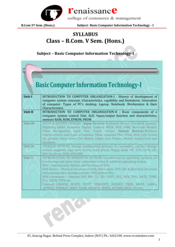
Shear in 3D As an example of three-dimensional shearing. the followingtransformation produces a z-axis shear: Parameters a and b can be assigned any real values. The effect of this transformation matrix is to alter x- and y-coordinatevalues by an amount that is proportional to the z value, while leavingthe z coordinate unchanged.
Shear in 3D A unit cube (a) is sheared (b) by transformation matrix with a b 1
References3d Object Representation :https://www.tutorialspoint.com/computer graphics/computer graphics surfaces.htm
Three Dimensional Concepts Three Dimensional Display Methods: The objects can be displayed in wire frame form, or we can apply lighting and surface rendering