Transcription
A Technical Tutorialon Digital Signal Synthesis Copyright 1999 Analog Devices, Inc.1
OutlineSection 1. Fundamentals of DDS technologyTheory of operationCircuit architectureTuning equationElements of DDS circuit functionality and capabilitiesDAC integrationTrends in functional integrationSection 2. Understanding the Sampled Output of a DDS OutputImplications of the Nyquist TheorumAliased images in the outputSource of aliased imagesCalculating the occurrence of aliased imagesQuantization considerationsSin(X)/X responseAC and DC linearity of the outputSection 3. Frequency/phase-hopping Capability of DDSCalculating the output tuning wordDetermining maximum tuning resolutionDetermining maximum tuning speedUnderstanding the DDS control interfacePre-programming profile registersSection 4. The DDS Output SpectrumThe effect of DAC resolution on spurious performanceThe effect of oversampling on spurious performanceThe effect of truncating the phase accumulator on spurious performanceAdditional DDS Spur sourcesWideband spur performanceNarrowband spur performancePredicting and exploiting spur "sweet spots" in a DDS' tuning rangeJitter and phase noise considerations in a DDS systemOutput filtering considerationsSection 5. High-speed Reference Clock ConsiderationsImplications of jitter and phase noise in the reference clockReference clock multipliersSFDR performance vs. the REFCLK Multiplier functionCopyright 1999 Analog Devices, Inc.2
Section 6. Interfacing to the DDS OutputOutput power considerationsFS output current range and tradeoffs vs. spur performanceSingle-ended vs. differential DAC outputDriving an output amplifierSection 7. DDS as a Clock GeneratorDefinition of clock generator application for a DDSSquaring the DDS output with an LP filter and comparatorManaging jitter in the clock generator applicationSection 8. Replacing/Integrating a PLL with a DDS SolutionTraditional analog synthesizer vs. the DDS implementationHow DDS can eliminate analog upconverter stagesExample of implementation of DDS as an LOSection 9. Digital Modulator Application of DDSBasic digital modulator theorySystem architecture and requirementsDigital filtersMultirate DSPClock and input data synchronization considerationsData encoding methodologies and DDS implementationsSection 10. Using Aliased Images to Generate Nyquist Frequencies from a DDSCreating and isolating aliased images in the DDS output spectrumSFDR performance expectations of the aliased imageAmplitude prediction of the aliased imageFrequency hopping considerations in the aliased image applicationSection 11. Ancillary DDS Techniques, Features, and FunctionsImproving SFDR with the addition of phase dither in the phase accumulatorUnderstanding DDS frequency “chirp” functionalityAchieving output amplitude control/modulation within a DDS deviceSynchronization multiple DDS devicesSection 12. Techniques for Bench Evaluation of a DDS SolutionPC-based evaluation platforms and reference designsCopyright 1999 Analog Devices, Inc.3
Section 13. Integrating DDS-based Hardware into a System EnvironmentAnalog/digital ground considerationsPower supply considerationsHigh-speed PCB layout techniquesSection 14. DDS Product Selection GuideAppendix A – Glossary of Related Electronic TermsAppendix B – Common Communications AcronymsAppendix C – An FM Modulator using DDSAppendix D – Pseudo-Random GeneratorAppendix E - Jitter Reduction in DDS Clock Generator SystemsCopyright 1999 Analog Devices, Inc.4
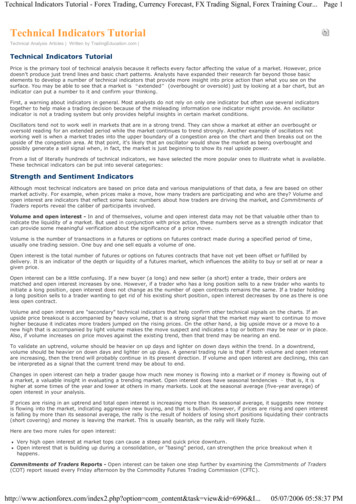
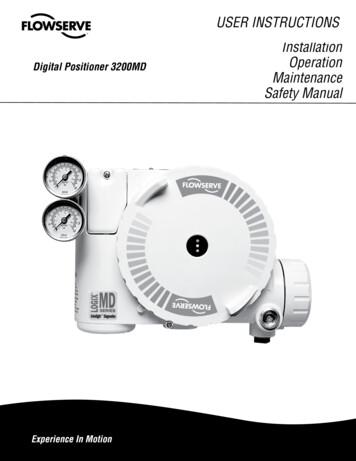
Section 1. Fundamentals of DDS TechnologyOverviewDirect digital synthesis (DDS) is a technique for using digital data processing blocks as a meansto generate a frequency- and phase-tunable output signal referenced to a fixed-frequencyprecision clock source. In essence, the reference clock frequency is “divided down” in a DDSarchitecture by the scaling factor set forth in a programmable binary tuning word. The tuningword is typically 24-48 bits long which enables a DDS implementation to provide superioroutput frequency tuning resolution.Today’s cost-competitive, high-performance, functionally-integrated, and small package-sizedDDS products are fast becoming an alternative to traditional frequency-agile analog synthesizersolutions. The integration of a high-speed, high-performance, D/A converter and DDSarchitecture onto a single chip (forming what is commonly known as a Complete-DDS solution)enabled this technology to target a wider range of applications and provide, in many cases, anattractive alternative to analog-based PLL synthesizers. For many applications, the DDS solutionholds some distinct advantages over the equivalent agile analog frequency synthesizer employingPLL circuitry.DDS advantages: Micro-Hertz tuning resolution of the output frequency and sub-degree phase tuningcapability, all under complete digital control. Extremely fast “hopping speed” in tuning output frequency (or phase), phase-continuousfrequency hops with no over/undershoot or analog-related loop settling time anomalies. The DDS digital architecture eliminates the need for the manual system tuning and tweakingassociated with component aging and temperature drift in analog synthesizer solutions. The digital control interface of the DDS architecture facilitates an environment wheresystems can be remotely controlled, and minutely optimized, under processor control. When utilized as a quadrature synthesizer, DDS afford unparalleled matching and control of Iand Q synthesized outputs.Theory of OperationIn its simplest form, a direct digital synthesizer can be implemented from a precision referenceclock, an address counter, a programmable read only memory (PROM), and a D/A converter (seeFigure 1-1).Copyright 1999 Analog Devices, Inc.5
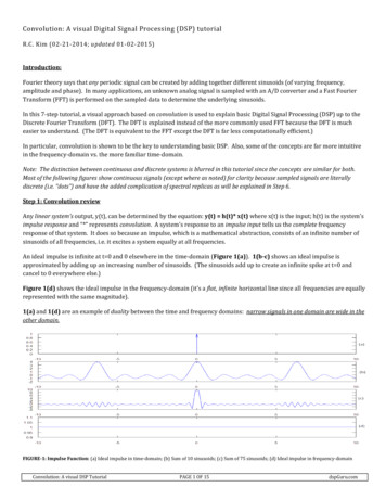
RfO U TN-BITSFigure 1-1. Simple Direct Digital SynthesizerIn this case, the digital amplitude information that corresponds to a complete cycle of a sinewaveis stored in the PROM. The PROM is therefore functioning as a sine lookup table. The addresscounter steps through and accesses each of the PROM’s memory locations and the contents (theequivalent sine amplitude words) are presented to a high-speed D/A converter. The D/Aconverter generates an analog sinewave in response to the digital input words from the PROM.The output frequency of this DDS implementation is dependent on 1.) the frequency of thereference clock, and 2.) the sinewave step size that is programmed into the PROM. While theanalog output fidelity, jitter, and AC performance of this simplistic architecture can be quitegood, it lacks tuning flexibility. The output frequency can only be changed by changing thefrequency of the reference clock or by reprogramming the PROM. Neither of these optionssupport high-speed output frequency hopping.With the introduction of a phase accumulator function into the digital signal chain, thisarchitecture becomes a numerically-controlled oscillator which is the core of a highly-flexibleDDS device. As figure 1-2 shows, an N-bit variable-modulus counter and phasePHASE ACCUMULATORn-bit CarryTUNING WORDM /ACONVERTER14-16BITSSYSTEM CLOCKFigure 1-2. Frequency-tunable DDS Systemregister are implemented in the circuit before the sine lookup table, as a replacement for theaddress counter. The carry function allows this function as a “phase wheel” in the DDSarchitecture. To understand this basic function, visualize the sinewave oscillation as a vectorCopyright 1999 Analog Devices, Inc.6fO U T
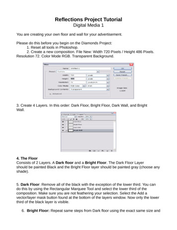
rotating around a phase circle (see Figure 1-3). Each designated point on the phase wheelcorresponds to the equivalent point on aDigital Phase WheelJump SizeMfO M x fC2N0000.01111.1nNUMBER OF 84354564294967296281474976710656Figure 1-3. Digital Phase Wheelcycle of a sine waveform. As the vector rotates around the wheel, visualize that a correspondingoutput sinewave is being generated. One revolution of the vector around the phase wheel, at aconstant speed, results in one complete cycle of the output sinewave. The phase accumulator isutilized to provide the equivalent of the vector’s linear rotation around the phase wheel. Thecontents of the phase accumulator correspond to the points on the cycle of the output sinewave.The number of discrete phase points contained in the “wheel” is determined by the resolution, N,of the phase accumulator. The output of the phase accumulator is linear and cannot directly beCopyright 1999 Analog Devices, Inc.7
used to generate a sinewave or any other waveform except a ramp. Therefore, a phase-toamplitude lookup table is used to convert a truncated version of the phase accumulator’sinstantaneous output value into the sinewave amplitude information that is presented to the D/Aconverter. Most DDS architectures exploit the symmetrical nature of a sinewave and utilizemapping logic to synthesize a complete sinewave cycle from ¼ cycle of data from the phaseaccumulator. The phase-to-amplitude lookup table generates all the necessary data by readingforward then back through the lookup table.RefClockDDS CircuitryNPhaseAccumulatorAmplitude/SineConv. AlgorithmD/AConverterTuning word specifies outputfrequency as a fraction of RefClock frequencySin (x)/xIn Digital DomainFigure 1-4. Signal flow through the DDS architectureThe phase accumulator is actually a modulus M counter that increments its stored number eachtime it receives a clock pulse. The magnitude of the increment is determined by a digital word Mcontained in a “delta phase register” that is summed with the overflow of the counter. The wordin the delta phase register forms the phase step size between reference clock updates; iteffectively sets how many points to skip around the phase wheel. The larger the jump size, thefaster the phase accumulator overflows and completes its equivalent of a sinewave cycle. For aN 32-bit phase accumulator, an M value of 0000 0001(one) would result in the phaseaccumulator overflowing after 232 reference clock cycles (increments). If the M value is changedto 0111 1111, the phase accumulator will overflow after only 21 clock cycles, or two referenceclock cycles. This control of the jump size constitutes the frequency tuning resolution of theDDS architecture.The relationship of the phase accumulator and delta phase accumulator form the basic tuningequation for DDS architecture:FOUT (M (REFCLK)) /2NWhere: FOUT the output frequency of the DDSM the binary tuning wordREFCLK the internal reference clock frequency (system clock)N The length in bits of the phase accumulatorCopyright 1999 Analog Devices, Inc.8
Changes to the value of M in the DDS architecture result in immediate and phase-continuouschanges in the output frequency. In practical application, the M value, or frequency tuning word,is loaded into an internal serial or byte-loaded register which precedes the parallel-output deltaphase register. This is generally done to minimize the package pin count of the DDS device.Once the buffer register is loaded, the parallel-output delta phase register is clocked and the DDSoutput frequency changes. Generally, the only speed limitation to changing the output frequencyof a DDS is the maximum rate at which the buffer register can be loaded and executed.Obviously, a parallel byte load control interface enhances frequency hopping capability.Trends in Functional IntegrationOne of the advantages to the digital nature of DDS architecture is that digital functional blockscan readily be added to the core blocks to enhance the capability and feature set of a givendevice. For general purpose use, a DDS device will include an integrated D/A converter functionto provide an analog output signal. This “complete-DDS” approach greatly enhances the overallusefulness and “user-friendliness” associated with the basic DDS devices. DDS devices arereadily available with integrated 10-bit D/A converters supporting internal REFCLK speeds to180 MHz. The present state of the art for a complete-DDS solution is at 300 MHz clock speedswith an integrated 12-bit D/A converter.Along with the integrated D/A converter, DDS solutions normally contain additional digitalblocks that perform various operations on the signal path. These blocks provide a higher level offunctionality in the DDS solution and provide an expanded set of user-controlled features. Theblock diagram of an expanded-feature DDS device is shown in Figure 1-5.The individual functional blocks are described below: (A) A programmable REFCLK Multiplier function include at the clock input, multiplies thefrequency of the external reference clock, thereby reducing the speed requirement on theprecision reference clock. The REFCLK Multiplier function also enhances the ability of theDDS device to utilize available system clock sources. (B) The addition of an adder after the phase accumulator enables the output sinewave to bephase-delayed in correspondence with a phase tuning word. The length of the adder circuitdetermines the number of bits in the phase tuning word, and therefore, the resolution of thedelay. In this architecture, the phase tuning word is 14-bits. (C) An Inverse SINC block inserted before the D/A converter compensates for the SIN(X)/Xresponse of the quantized D/A converter output, and thereby provides a constant amplitudeoutput over the Nyquist range of the DDS device (D) A digital multiplier inserted between the Sine look-up table and the D/A converterenables amplitude modulation of the output sinewave. The width of the digital multiplierword determines the resolution of the output amplitude step size.Copyright 1999 Analog Devices, Inc.9
D A C RSETDDSMultiplierPhaseAccumulator4X - 20XRef. ClockFrequencyAccumulatorReferenceClock InPhase Offset/ModulationDigital ne-to-AmplitudeConverter300 MHzDiff/SingleSelectSystemClockFSK/BPSK/HOLDData InBi-directionalI
Direct digital synthesis (DDS) is a technique for using digital data processing blocks as a means to generate a frequency- and phase-tunable output signal referenced to a fixed-frequency precision clock source. In essence, the reference clock frequency is “divided down” in a DDSFile Size: 901KBPage Count: 122
![Unreal Engine 4 Tutorial Blueprint Tutorial [1] Basic .](/img/5/ue4-blueprints-tutorial-2018.jpg)