Transcription
This page intentionally left blank
P1: KAE0521881210preCUFX149/Hosford0 521 88121 8printer: SheridanMETAL FORMING, THIRD EDITIONThis book is designed to help the engineer understand the principles of metalforming and analyze forming problems – both the mechanics of forming processesand how the properties of metals interact with the processes. The first third ofthe book is devoted to fundamentals of mechanics and materials; the middle toanalyses of bulk forming processes such as drawing, extrusion, and rolling; andthe last third covers sheet forming processes. In this new third edition, an entirechapter has been devoted to forming limit diagrams; another to various aspectsof stamping, including the use of tailor-welded blanks; and another to other sheetforming operations, including hydroforming of tubes. Sheet testing is covered ina later chapter. Coverage of sheet metal properties has been expanded to includenew materials and more on aluminum alloys. Interesting end-of-chapter notes andreferences have been added throughout. More than 200 end-of-chapter problemsare also included.William F. Hosford is a Professor Emeritus of Materials Science and Engineeringat the University of Michigan. Professor Hosford is the author of more than 80technical articles and a number of books, including the leading selling Mechanicsof Crystals and Textured Polycrystals, Physical Metallurgy, Mechanical Behaviorof Materials, and Materials Science: An Intermediate Text.Robert M. Caddell was a professor of mechanical engineering at the University ofMichigan, Ann Arbor.iOctober 4, 200717:44
P1: KAE0521881210preCUFX149/Hosford0 521 88121 8printer: SheridaniiOctober 4, 200717:44
P1: KAE0521881210preCUFX149/Hosford0 521 88121 8printer: SheridanMETAL FORMINGMechanics and MetallurgyTHIRD EDITIONWILLIAM F. HOSFORDUniversity of Michigan, Ann ArborROBERT M. CADDELLLate of University of Michigan, Ann ArboriiiOctober 4, 200717:44
CAMBRIDGE UNIVERSITY PRESSCambridge, New York, Melbourne, Madrid, Cape Town, Singapore, São PauloCambridge University PressThe Edinburgh Building, Cambridge CB2 8RU, UKPublished in the United States of America by Cambridge University Press, New Yorkwww.cambridge.orgInformation on this title: www.cambridge.org/9780521881210 William F. Hosford 2007This publication is in copyright. Subject to statutory exception and to the provision ofrelevant collective licensing agreements, no reproduction of any part may take placewithout the written permission of Cambridge University Press.First published in print format 2007eBook (EBL)ISBN-13 978-0-511-35453-3ISBN-10 0-511-35453-3eBook ck0-521-88121-8Cambridge University Press has no responsibility for the persistence or accuracy of urlsfor external or third-party internet websites referred to in this publication, and does notguarantee that any content on such websites is, or will remain, accurate or appropriate.
P1: KAE0521881210preCUFX149/Hosford0 521 88121 8printer: SheridanOctober 4, 2007ContentsPreface to Third Edition1Stress and Strain . . . . . . . . . . . . . . . . . . . . . . . . . . . . . . . . . . . . . . . . 11.11.21.31.41.51.61.71.81.91.101.112page xiiiStressStress transformationPrincipal stressesMohr’s circle equationsStrainSmall strainsThe strain tensorIsotropic elasticityStrain energyForce and moment balancesBoundary conditions1245791010111213NOTES OF INTEREST . . . . . . . . . . . . . . . . . . . . . . . . . . . . . . . . . . . . . . . . . . . . . .14REFERENCES . . . . . . . . . . . . . . . . . . . . . . . . . . . . . . . . . . . . . . . . . . . . . . . . . . . .15APPENDIX – EQUILIBRIUM EQUATIONS . . . . . . . . . . . . . . . . . . . . . . . . . . . . . . . .15PROBLEMS . . . . . . . . . . . . . . . . . . . . . . . . . . . . . . . . . . . . . . . . . . . . . . . . . . . . . .15Plasticity . . . . . . . . . . . . . . . . . . . . . . . . . . . . . . . . . . . . . . . . . . . . . 172.12.22.32.42.52.62.72.82.9Yield criteriaTresca criterionVon Mises criterionPlastic workEffective stressEffective strainFlow rulesNormality principleDerivation of the von Mises effective strainNOTES OF INTEREST . . . . . . . . . . . . . . . . . . . . . . . . . . . . . . . . . . . . . . . . . . . . . .17182021222223252627v17:44
P1: KAE0521881210previCUFX149/Hosford0 521 88121 8printer: SheridanOctober 4, 2007CONTENTS3REFERENCES . . . . . . . . . . . . . . . . . . . . . . . . . . . . . . . . . . . . . . . . . . . . . . . . . . . .28PROBLEMS . . . . . . . . . . . . . . . . . . . . . . . . . . . . . . . . . . . . . . . . . . . . . . . . . . . . . .28Strain Hardening . . . . . . . . . . . . . . . . . . . . . . . . . . . . . . . . . . . . . . . 303.13.23.33.43.53.63.73.83.93.10440REFERENCES . . . . . . . . . . . . . . . . . . . . . . . . . . . . . . . . . . . . . . . . . . . . . . . . . . . .40PROBLEMS . . . . . . . . . . . . . . . . . . . . . . . . . . . . . . . . . . . . . . . . . . . . . . . . . . . . . .41Instability . . . . . . . . . . . . . . . . . . . . . . . . . . . . . . . . . . . . . . . . . . . . 43Uniaxial tensionEffect of inhomogeneitiesBalanced biaxial tensionPressurized thin-wall sphereSignificance of instability4344454748NOTE OF INTEREST . . . . . . . . . . . . . . . . . . . . . . . . . . . . . . . . . . . . . . . . . . . . . . .49REFERENCES . . . . . . . . . . . . . . . . . . . . . . . . . . . . . . . . . . . . . . . . . . . . . . . . . . . .49PROBLEMS . . . . . . . . . . . . . . . . . . . . . . . . . . . . . . . . . . . . . . . . . . . . . . . . . . . . . .49Temperature and Strain-Rate Dependence . . . . . . . . . . . . . . . . . . . . . NOTE OF INTEREST . . . . . . . . . . . . . . . . . . . . . . . . . . . . . . . . . . . . . . . . . . . . . . .4.14.24.34.44.55The tension testElastic–plastic transitionEngineering vs. true stress and strainA power-law expressionOther strain hardening approximationsBehavior during neckingCompression testingBulge testingPlane-strain compressionTorsion testingStrain rateSuperplasticityEffect of inhomogeneitiesCombined strain and strain-rate effectsAlternative description of strain-rate dependenceTemperature dependence of flow stressDeformation mechanism mapsHot workingTemperature rise during deformation525558626365696971NOTES OF INTEREST . . . . . . . . . . . . . . . . . . . . . . . . . . . . . . . . . . . . . . . . . . . . . .72REFERENCES . . . . . . . . . . . . . . . . . . . . . . . . . . . . . . . . . . . . . . . . . . . . . . . . . . . .73PROBLEMS . . . . . . . . . . . . . . . . . . . . . . . . . . . . . . . . . . . . . . . . . . . . . . . . . . . . . .73Work Balance . . . . . . . . . . . . . . . . . . . . . . . . . . . . . . . . . . . . . . . . . 766.1Ideal work7617:44
P1: KAE0521881210preCUFX149/Hosford0 521 88121 8printer: SheridanOctober 4, 2007viiCONTENTS6.26.36.46.56.6782PROBLEMS . . . . . . . . . . . . . . . . . . . . . . . . . . . . . . . . . . . . . . . . . . . . . . . . . . . . . .82Slab Analysis and Friction . . . . . . . . . . . . . . . . . . . . . . . . . . . . . . . . . 85Sheet drawingWire and rod drawingFriction in plane-strain compressionSticking frictionMixed sticking–sliding conditionsConstant shear stress interfaceAxially symmetric compressionSand-pile analogyFlat rollingRoll flatteningRoll bendingCoiningDry frictionLubricantsExperimental findingsRing friction S . . . . . . . . . . . . . . . . . . . . . . . . . . . . . . . . . . . . . . . . . . . . . . . . . . .106PROBLEMS . . . . . . . . . . . . . . . . . . . . . . . . . . . . . . . . . . . . . . . . . . . . . . . . . . . . .106Upper-Bound Analysis . . . . . . . . . . . . . . . . . . . . . . . . . . . . . . . . . . S . . . . . . . . . . . . . . . . . . . . . . . . . . . . . . . . . . . . . . . . . . . . . . . . . . . 157.168Extrusion and drawingDeformation efficiencyMaximum drawing reductionEffects of die angle and reductionSwagingUpper boundsEnergy dissipation on plane of shearPlane-strain frictionless extrusionPlane-strain frictionless indentationPlane-strain compressionAnother approach to upper boundsCombined upper-bound analysisPlane-strain drawingAxisymmetric drawing110111112116116119120121121REFERENCES . . . . . . . . . . . . . . . . . . . . . . . . . . . . . . . . . . . . . . . . . . . . . . . . . . .123PROBLEMS . . . . . . . . . . . . . . . . . . . . . . . . . . . . . . . . . . . . . . . . . . . . . . . . . . . . .123Slip-Line Field Analysis . . . . . . . . . . . . . . . . . . . . . . . . . . . . . . . . . . 1289.19.2IntroductionGoverning stress equations12812817:44
P1: KAE0521881210previiiCUFX149/Hosford0 521 88121 8printer: SheridanOctober 4, REFERENCES . . . . . . . . . . . . . . . . . . . . . . . . . . . . . . . . . . . . . . . . . . . . . . . . . . .150APPENDIX . . . . . . . . . . . . . . . . . . . . . . . . . . . . . . . . . . . . . . . . . . . . . . . . . . . . . .150PROBLEMS . . . . . . . . . . . . . . . . . . . . . . . . . . . . . . . . . . . . . . . . . . . . . . . . . . . . .153Deformation-Zone Geometry . . . . . . . . . . . . . . . . . . . . . . . . . . . . . . 163The parameterFrictionRedundant deformationInhomogeneityInternal damageResidual stressesComparison of plane-strain and axisymmetric deformation163164164166171175178NOTE OF INTEREST . . . . . . . . . . . . . . . . . . . . . . . . . . . . . . . . . . . . . . . . . . . . . .180REFERENCES . . . . . . . . . . . . . . . . . . . . . . . . . . . . . . . . . . . . . . . . . . . . . . . . . . .180PROBLEMS . . . . . . . . . . . . . . . . . . . . . . . . . . . . . . . . . . . . . . . . . . . . . . . . . . . . .180Formability . . . . . . . . . . . . . . . . . . . . . . . . . . . . . . . . . . . . . . . . . . 142146147NOTES OF INTEREST . . . . . . . . . . . . . . . . . . . . . . . . . . . . . . . . . . . . . . . . . . . . .10.110.210.310.410.510.610.711Boundary conditionsPlane-strain indentationHodographs for slip-line fieldsPlane-strain extrusionEnergy dissipation in a slip-line fieldMetal distortionIndentation of thick slabsPlane-strain drawingConstant shear–stress interfacesPipe formationDuctilityMetallurgyDuctile fractureHydrostatic stressBulk formability testsFormability in hot working182182186187191192NOTE OF INTEREST . . . . . . . . . . . . . . . . . . . . . . . . . . . . . . . . . . . . . . . . . . . . . .193REFERENCES . . . . . . . . . . . . . . . . . . . . . . . . . . . . . . . . . . . . . . . . . . . . . . . . . . .193PROBLEMS . . . . . . . . . . . . . . . . . . . . . . . . . . . . . . . . . . . . . . . . . . . . . . . . . . . . .193Bending . . . . . . . . . . . . . . . . . . . . . . . . . . . . . . . . . . . . . . . . . . . . . 19512.112.212.312.4Sheet bendingBending with superimposed tensionNeutral axis shiftBendability19519820020117:44
P1: KAE0521881210preCUFX149/Hosford0 521 88121 8printer: SheridanOctober 4, 2007ixCONTENTS1312.5 Shape bending12.6 Forming limits in bending202203NOTE OF INTEREST . . . . . . . . . . . . . . . . . . . . . . . . . . . . . . . . . . . . . . . . . . . . . .203REFERENCES . . . . . . . . . . . . . . . . . . . . . . . . . . . . . . . . . . . . . . . . . . . . . . . . . . .205PROBLEMS . . . . . . . . . . . . . . . . . . . . . . . . . . . . . . . . . . . . . . . . . . . . . . . . . . . . .205Plastic Anisotropy . . . . . . . . . . . . . . . . . . . . . . . . . . . . . . . . . . . . . . 20713.113.213.313.413.513.614Crystallographic basisMeasurement of RHill’s anisotropic plasticity theorySpecial cases of Hill’s yield criterionNonquadratic yield criteriaCalculation of anisotropy from crystallographic considerations207209209211212215NOTE OF INTEREST . . . . . . . . . . . . . . . . . . . . . . . . . . . . . . . . . . . . . . . . . . . . . .216REFERENCES . . . . . . . . . . . . . . . . . . . . . . . . . . . . . . . . . . . . . . . . . . . . . . . . . . .216PROBLEMS . . . . . . . . . . . . . . . . . . . . . . . . . . . . . . . . . . . . . . . . . . . . . . . . . . . . .216Cupping, Redrawing, and Ironing . . . . . . . . . . . . . . . . . . . . . . . . . . 22014.114.214.314.414.514.614.714.814.915Cup drawingAnisotropic effects in drawingEffects of strain hardening in drawingAnalysis of assumptionsEffects of tooling on cup drawingEaringRedrawingIroningResidual stresses220223224225227228230231233NOTES OF INTEREST . . . . . . . . . . . . . . . . . . . . . . . . . . . . . . . . . . . . . . . . . . . . .234REFERENCES . . . . . . . . . . . . . . . . . . . . . . . . . . . . . . . . . . . . . . . . . . . . . . . . . . .234PROBLEMS . . . . . . . . . . . . . . . . . . . . . . . . . . . . . . . . . . . . . . . . . . . . . . . . . . . . .234Forming Limit Diagrams . . . . . . . . . . . . . . . . . . . . . . . . . . . . . . . . . 23715.115.215.315.415.515.615.7Localized neckingForming limit diagramsExperimental determination of FLDsCalculation of forming limit diagramsFactors affecting forming limitsChanging strain pathsStress-based forming limits237241242244247251253NOTE OF INTEREST . . . . . . . . . . . . . . . . . . . . . . . . . . . . . . . . . . . . . . . . . . . . . .253REFERENCES . . . . . . . . . . . . . . . . . . . . . . . . . . . . . . . . . . . . . . . . . . . . . . . . . . .253PROBLEMS . . . . . . . . . . . . . . . . . . . . . . . . . . . . . . . . . . . . . . . . . . . . . . . . . . . . .25317:44
P1: KAE0521881210prexCUFX149/Hosford0 521 88121 8printer: SheridanOctober 4, 2007CONTENTS16Stamping . . . . . . . . . . . . . . . . . . . . . . . . . . . . . . . . . . . . . . . . . . . . 7267REFERENCES . . . . . . . . . . . . . . . . . . . . . . . . . . . . . . . . . . . . . . . . . . . . . . . . . . .268PROBLEMS . . . . . . . . . . . . . . . . . . . . . . . . . . . . . . . . . . . . . . . . . . . . . . . . . . . . .268Other Sheet-Forming Operations . . . . . . . . . . . . . . . . . . . . . . . . . . . 270Roll formingSpinningHydroforming of tubesFree expansion of tubesHydroforming into square cross sectionBent sectionsShearing270271272272274276276REFERENCES . . . . . . . . . . . . . . . . . . . . . . . . . . . . . . . . . . . . . . . . . . . . . . . . . . .277PROBLEMS . . . . . . . . . . . . . . . . . . . . . . . . . . . . . . . . . . . . . . . . . . . . . . . . . . . . .277Formability Tests . . . . . . . . . . . . . . . . . . . . . . . . . . . . . . . . . . . . . . 0261261262265267NOTES OF INTEREST . . . . . . . . . . . . . . . . . . . . . . . . . . . . . . . . . . . . . . . . . . . . .17.117.217.317.417.517.617.718StampingDraw beadsStrain distributionLoose metal and wrinklingFlangingSpringbackStrain signaturesTailor-welded blanksDie designToughness and sheet tearingGeneral observationsCupping testsLDH testPost-uniform elongationOSU formability testHole expansionHydraulic bulge testDuncan friction test279281282282283284285REFERENCES . . . . . . . . . . . . . . . . . . . . . . . . . . . . . . . . . . . . . . . . . . . . . . . . . . .286PROBLEMS . . . . . . . . . . . . . . . . . . . . . . . . . . . . . . . . . . . . . . . . . . . . . . . . . . . . .286Sheet Metal Properties . . . . . . . . . . . . . . . . . . . . . . . . . . . . . . . . . . 28919.119.219.319.419.5IntroductionSurface appearanceStrain agingAluminum-killed steelsInterstitial-free steels28929029029529517:44
P1: KAE0521881210preCUFX149/Hosford0 521 88121 8printer: SheridanOctober 4, 19.1419.1519.1619.1719.18HSLA steelsDual-phase and complex-phase steelsTransformation-induced plasticity (TRIP) steelsMartensitic steelsTrendsSpecial sheet steelsSurface treatmentStainless steelsAluminum alloysCopper and brassHexagonal close-packed metalsToolingProduct OTES OF INTEREST . . . . . . . . . . . . . . . . . . . . . . . . . . . . . . . . . . . . . . . . . . . . .306REFERENCES . . . . . . . . . . . . . . . . . . . . . . . . . . . . . . . . . . . . . . . . . . . . . . . . . . .306PROBLEMS . . . . . . . . . . . . . . . . . . . . . . . . . . . . . . . . . . . . . . . . . . . . . . . . . . . . .306Index30917:44
P1: KAE0521881210preCUFX149/Hosford0 521 88121 8printer: SheridanxiiOctober 4, 200717:44
P1: KAE0521881210preCUFX149/Hosford0 521 88121 8printer: SheridanOctober 4, 2007Preface to Third EditionMy coauthor Robert Caddell died in 1990. I have greatly missed interacting with him.The biggest changes from the second edition are an enlargement and reorganizationof the last third of the book, which deals with sheet metal forming. Changes have beenmade to the chapters on bending, plastic anisotropy, and cup drawing. An entire chapterhas been devoted to forming limit diagrams. There is one chapter on various aspectsof stampings, including the use of tailor-welded blanks, and another on other sheetforming operations, including hydroforming of tubes. Sheet testing is covered in aseparate chapter. The chapter on sheet metal properties has been expanded to includenewer materials and more depth on aluminum alloys.In addition, some changes have been made to the chapter on strain-rate sensitivity.A treatment of friction and lubrication has been added. A short treatment of swaginghas been added. End-of-chapter notes have been added for interest and additionalend-of-chapter references have been added.No attempt has been made in this book to introduce numerical methods such asfinite element analyses. The book Metal Forming Analysis by R. H. Wagoner and J. L.Chenot (Cambridge University Press, 2001) covers the latest numerical techniques.We feel that one should have a thorough understanding of a process before attemptingnumerical techniques. It is vital to understand what constitutive relations are imbeddedin a program before using it. For example, the use of Hill’s 1948 anisotropic yieldcriterion can lead to significant errors.Joining techniques such as laser welding and friction welding are not covered.I wish to acknowledge the membership in the North American Deep DrawingGroup from which I have learned much about sheet metal forming. Particular thanksare given to Alejandro Graf of ALCAN, Robert Wagoner of the Ohio State University,John Duncan of the University of Auckland, Thomas Stoughton and David Meulemanof General Motors, and Edmund Herman of Creative Concepts.xiii17:44
P1: KAE0521881210preCUFX149/Hosford0 521 88121 8printer: SheridanxivOctober 4, 200717:44
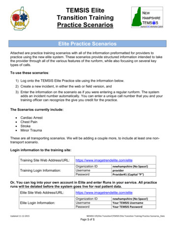
P1: KAE0521881210c01CUFX149/Hosford0 521 88121 8printer: SheridanOctober 4, 20071 Stress and StrainAn understanding of stress and strain is essential for analyzing metal forming operations. Often the words stress and strain are used synonymously by the nonscientificpublic. In engineering, however, stress is the intensity of force and strain is a measureof the amount of deformation.1.1 STRESSStress is defined as the intensity of force, F, at a point.σ F/ Aas A 0,(1.1)where A is the area on which the force acts.If the stress is the same everywhere,σ F/A.(1.2)There are nine components of stress as shown in Figure 1.1. A normal stress componentis one in which the force is acting normal to the plane. It may be tensile or compressive.A shear stress component is one in which the force acts parallel to the plane.Stress components are defined with two subscripts. The first denotes the normalto the plane on which the force acts and the second is the direction of the force. Forexample, σx x is a tensile stress in the x-direction. A shear stress acting on the x-planein the y-direction is denoted σx y .Repeated subscripts (e.g., σx x , σ yy , σzz ) indicate normal stresses. They are tensileif both subscripts are positive or both are negative. If one is positive and the otheris negative, they are compressive. Mixed subscripts (e.g., σzx , σx y , σ yz ) denote shearstresses. A state of stress in tensor notation is expressed as σx x σ yx σzx (1.3)σi j σx y σ yy σzy , σx z σ yz σzz The use of the opposite convention should cause no problem because σi j σ ji .121:37
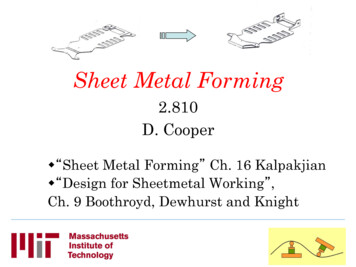
P1: KAE0521881210c012CUFX149/Hosford0 521 88121 8printer: SheridanOctober 4, 2007STRESS AND STRAINz σzzσzyσzxσyzσxzσxyσxx1.1. Nine components of stress acting on aninfinitesimal element.σyyσyxyxwhere i and j are iterated over x, y, and z. Except where tensor notation is required, itis simpler to use a single subscript for a normal stress and denote a shear stress by τ .For example, σx σx x and τx y σx y .1.2 STRESS TRANSFORMATIONStress components expressed along one set of axes may be expressed along any otherset of axes. Consider resolving the stress component σ y Fy /Ay onto the x and y axesas shown in Figure 1.2.The force Fy in the y direction is Fy Fy cos θ and the area normal to y isA y A y / cos θ, soσ y Fy /A y Fy cos θ/(A y / cos θ) σ y cos2 θ.(1.4a)Similarlyτ y x Fx /A y Fy sin θ/(A y / cos θ) σ y cos θ sin θ.(1.4b)Note that transformation of stresses requires two sine and/or cosine terms.Pairs of shear stresses with the same subscripts in reverse order are always equal(e.g., τi j τ ji ). This is illustrated in Figure 1.3 by a simple moment balance on anFyyyFyAy1.2. The stresses acting on a plane, A , under anormal stress, σy .Fxθxx21:37
P1: KAE0521881210c01CUFX149/Hosford0 521 88121 8printer: SheridanOctober 4, 200731.2. STRESS TRANSFORMATIONτxyy1.3. Unless τxy τyx , there would not be amoment balance.τyxτyxxτxyinfinitesimal element. Unless τi j τ ji , there would be an infinite rotational acceleration. Thereforeτi j τ ji .(1.5)The general equation for transforming the stresses from one set of axes (e.g., n, m, p)to another set of axes (e.g., i, j, k) isσi j 33 im jn σmn .(1.6)n 1 m 1Here, the term im is the cosine of the angle between the i and m axes and the term jnis the cosine of the angle between the j and n axes. This is often written asσi j im jn σmn ,(1.7)with the summation implied. Consider transforming stresses from the x, y, z axis systemto the x , y , z system shown in Figure 1.4.Using equation 1.6,σx x x x x x σx x x x x y σx y x x x z σx z x y x x σ yx x y x y σ yy x y x z σ yz x z x x σzx x z x y σ yz x z x z σzz(1.8a)andσx y x x y x σx x x x y y σx y x x y z σx z x y y x σ yx x y y y σ yy x y y z σ yz x z y x σzx x z y y σ yz x z y z σzz(1.8b)zzyy1.4. Two orthogonal coordinate systems.xx21:37
P1: KAE0521881210c014CUFX149/Hosford0 521 88121 8printer: SheridanOctober 4, 2007STRESS AND STRAINThese can be simplified toσx 2x x σx 2x y σ y 2x z σz 2 x y x z τ yz 2 x z x x τzx 2 x x x y τx y(1.9a)andτx y x x y x σx x y y y σ y x z y z σz ( x y y z x z y y )τ yz ( x z y x x x y z )τzx ( x x y y x y y x )τx y .(1.9b)1.3 PRINCIPAL STRESSESIt is always possible to find a set of axes along which the shear stress terms vanish. Inthis case σ1 , σ2 , and σ3 are called the principal stresses. The magnitudes of the principalstresses, σp , are the roots ofσp3 I1 σp2 I2 σp I3 0,(1.10)where I1 , I2 , and I3 are called the invariants of the stress tensor. They areI1 σx x σ yy σzz ,22 σzx σx2y σ yy σzz σzz σx x σx x σ yy ,I2 σ yzand(1.11)22I3 σx x σ yy σzz 2σ yz σzx σx y σx x σ yz σ yy σzx σzz σx2y .The first invariant I1 p/3 where p is the pressure. I1 , I2 , and I3 are independent ofthe orientation of the axes. Expressed in terms of the principal stresses, they areI 1 σ1 σ2 σ3 ,I2 σ2 σ3 σ3 σ1 σ1 σ2 ,and(1.12)I 3 σ1 σ2 σ3 .EXAMPLE 1.1: Consider a stress state with σx 70 MPa, σ y 35 MPa, τx y 20, σz τzx τ yz 0. Find the principal stresses using equations 1.10 and 1.11.SOLUTION: Using equations 1.11, I1 105 MPa, I2 –2050 MPa, I3 0. Fromequation 1.10, σp3 105σp2 2050σp 0 0, soσp2 105σp 2,050 0.The principal stresses are the roots σ1 79.1 MPa, σ2 25.9 MPa, and σ3 σz 0.EXAMPLE 1.2: Repeat Example 1.1 with I3 170,700.SOLUTION: The principal stresses are the roots of σp3 105σp2 2050σp 170,700 0.Since one of the roots is σz σ3 40, σp 40 0 can be factored out. This givesσp2 105σp 2050 0, so the other two principal stresses are σ1 79.1 MPa, σ2 25.9 MPa. This shows that when σz is one of the principal stresses, the other twoprincipal stresses are independent of σz .21:37
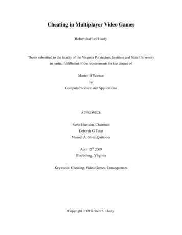
P1: KAE0521881210c01CUFX149/Hosford0 521 88121 8printer: SheridanOctober 4, 200751.4. MOHR’S CIRCLE EQUATIONS1.4 MOHR’S CIRCLE EQUATIONSIn the special cases where two of the three shear stress terms vanish (e.g., τ yx τzx 0), the stress σz normal to the x y plane is a principal stress and the other two principalstresses lie in the x y plane. This is illustrated in Figure 1.5.For these conditions x z y z 0, τ yz τzx 0, x x y y cos φ, and x y y x sin φ. Substituting these relations into equations 1.9 results inτx y cos φ sin φ( σx σ y ) (cos 2 φ sin 2 φ)τx y ,σx (cos2 φ)σx (sin2 φ)σ y 2(cos φ sin φ)τx y ,and(1.13)σ y (sin φ)σx (cos φ)σ y 2(cos φ sin φ)τx y .22These can be simplified with the trigonometric relationssin 2φ 2 sin φ cos φandcos 2φ cos2 φ sin2 φto obtainτx y sin 2φ(σx σ y )/2 (cos 2φ)τ x y ,(1.14a)σ (σx σ y )/2 cos 2φ(σx σ y )/2 τ x y sin 2φ,x and(1.14b)σ (σx σ y )/2 cos 2φ(σx σ y )/2 τ x y sin 2φ.(1.14c)y If τx y is set to zero in equation 1.14a, φ becomes the angle θ between the principalaxes and the x and y axes. Thentan 2θ τx y /[(σx σ y )/2].(1.15)The principal stresses, σ1 and σ2 , are then the values of σx and σ y σ1,2 (σx σ y )/2 (1/2)[(σx σ y ) cos 2θ] τx y sin 2θ 1/2σ1,2 (σx σ y )/2 (1/2) (σx σ y )2 σxyφx1.5. Stress state for which the Mohr’s circle equations apply.x21:37
P1: KAE0521881210c016CUFX149/Hosford0 521 88121 8printer: SheridanOctober 4, 2007STRESS AND 2σ1σ(σx σy)/2σy1.6. Mohr’s circle diagram for stress.τσxσ3σ2τxy2θσ1σσy1.7. Three-dimensional Mohr’s circles for stresses.A Mohr’s circle diagram is a graphical representation of equations 1.16 and 1.17.They form a circle of radius (σ1 σ2 )/2 with the center at (σ1 σ2 )/2 as shown inFigure 1.6. The normal stress components are plotted on the ordinate and the shearstress components are plotted on the abscissa.Using the Pythagorean theorem on the triangle in Figure 1.6, 1/2 (1.17)(σ1 σ2 )/2 [(σx σ y )/2]2 τx2yandtan 2θ τx y /[(σx σ y )/2].(1.18)A three-dimensional stress state can be represented by three Mohr’s circles asshown in Figure 1.7. The three principal stresses σ1 , σ2 , and σ3 are plotted on theordinate. The circles represent the stress state in the 1–2, 2–3, and 3–1 planes.EXAMPLE 1.3: Construct the Mohr’s circle for the stress state in Example 1.2 anddetermine the largest shear stress. O. Mohr, Zivilingeneur (1882), p. 113.21:37
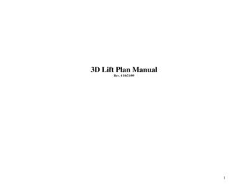
P1: KAE0521881210c01CUFX149/Hosford0 521 88121 8printer: SheridanOctober 4, 200771.5. STRAINτ max 59.6τσy1.8. Mohr’s circleExample 1.2.forstressstatein 35σ 3 -40τ xy 20σσ1 79.1σ2 25.9σx 70A 01.9. Deformation, translation, and rotation of aline in a material.A′ BB′SOLUTION: The Mohr’s circle is plotted in Figure 1.8. The largest shear stress isτmax (σ1 σ3 )/2 [79.1 ( 40)]/2 59.6 MPa.1.5 STRAINStrain describes the amount of deformation in a body. When a body is deformed, pointsin that body are displaced. Strain must be defined in such a way that it excludes effectsof rotation and translation. Figure 1.9 shows a line in a material that has been that hasbeen deformed. The line has been translated, rotated, and deformed. The deformationis characterized by the engineering or nominal strain, e:e ( 0 )/ 0 / 0 .(1.19)An alternative definition is that of true or logarithmic strain, ε, defined bydε d / ,(1.20)ε ln( / 0 ) ln(1 e).(1.21)which on integrating givesThe true and engineering strains are almost equal when they are small. Expressingε as ε ln( / 0 ) ln(1 e) and expanding,ε e e2 /2 e3 /3! · · · , so as e 0, ε e.There are several reasons why true strains are more convenient than engineeringstrains. The following examples indicate why. First defined by P. Ludwig, Elemente der Technishe Mechanik, Springer, 1909.21:37
P1: KAE0521881210c018CUFX149/Hosford0 521 88121 8printer: SheridanOctober 4, 2007STRESS AND STRAINEXAMPLE 1.4:(a) A bar of length 0 is uniformly extended until its length 2 0 . Compute thevalues of the engineering and true strains.(b) To what final length must a bar of length 0 be compressed if the strains are thesame (except sign) as in part (a)?SOLUTION:(a) e / 0 1.0, ε ln( / 0 ) ln 2 0.693.(b) e 1 ( 0 )/ 0 , so 0. This is clearly impossible to achieve.ε 0.693 ln( / 0 ), so 0 exp(0.693) 0 /2.EXAMPLE 1.5: A bar 10 cm long is elongated to 20 cm by rolling in three steps: 10cm to 12 cm, 12 cm to 15 cm, and 15 cm to 20 cm.(a) Calculate the engineering strain for each step and compare the sum of these withthe overall engineering strain.(b) Repeat for true strains.SOLUTION:(a) e1 2/10 0.20, e2 3/12 0.25, e3 5/15 0.333, etot 0.20 .25 .333 0.783. eoverall 10/10 1.(b) ε1 ln(12/10) 0.182, ε2 ln(15/12) 0.223, ε3 ln(20/15) 0.288, εtot 0.693, εoverall ln(20/10) 0.693.With true strains, the sum of the increments equals the overall strain, but this is not sowith engineering strains.EXAMPLE 1.6: A b
the last third covers sheet forming processes. In this new third edition, an entire chapter has been devoted to forming limit diagrams; another to various aspects of stamping, including the use of tailor-welded blanks; and another to other sheet forming operations, including hydroforming of tubes.