Transcription
NASA Visible Infrared Imaging Radiometer SuiteLevel-1B Product User Guide [Collection-1]May 2018 [Version 1.0]Level-1 and Atmosphere Archive & Distribution SystemNASA Goddard Space Flight CenterGreenbelt, Maryland1
Change-History LogVersionDateChange Description1.0May 31, 2018Publicly released version2
NASA VIIRS Level-1B Product User GuideTable of Contents1.0INTRODUCTION .51.1ACKNOWLEDGEMENTS . 61.2QUESTIONS/FEEDBACK, ETC. . 62.0VIIRS INSTRUMENT OVERVIEW .72.1DESIGN AND HERITAGE. 72.2VIIRS BAND CONFIGURATION AND RELATED DETAILS . 72.3ON-BOARD AGGREGATION, AGGREGATION ZONES, AND BOW-TIE DELETION . 92.4REFLECTIVE SOLAR BAND AND THERMAL EMISSIVE BAND CALIBRATION . 92.5UNCERTAINTY INDEX .103.0NASA VIIRS LEVEL-1 PROCESSING FLOW .114.0LEVEL-1 GEOLOCATION DATA PRODUCT.134.1GEOLOCATION DATA .134.2NAVIGATION DATA .174.3SCAN LINE ATTRIBUTES.185.0LEVEL-1B EARTH-VIEW PRODUCTS .195.1OBSERVATION DATA .195.2SCAN LINE ATTRIBUTES.245.3DIAGNOSTICS.246.0NASA L1B: PRODUCT STATUS, FILENAMES, DATA ORDERING/HANDLING, ETC. .257.0KNOWN CALIBRATION ISSUES IN THE NASA VIIRS LEVEL-1B PRODUCT.278.0ABBREVIATIONS AND ACRONYMS [COMING SOON] .289.0REFERENCES.293
10.0APPENDIX-1: VIIRS LEVEL-1B QUALITY FLAGS .3010.1INTRODUCTION .3010.2PIXEL QUALITY FLAG .3010.2.1VIIRS Level-1B Pixel Quality Flag Approach .3010.2.2IDPS SDR Pixel Quality Flag Approach.3310.3SCAN QUALITY FLAG .3410.3.1VIIRS Level-1B Scan Quality Flagging.3410.3.2IDPS SDR Scan Quality Flags .3511.0APPENDIX-2: VIIRS GEOLOCATION QUALITY FLAGS .3611.1INTRODUCTION .3611.2PIXEL QUALITY FLAG .3611.2.1VIIRS Geolocation Product Pixel Quality Flag Approach.3611.2.2VIIRS Geolocation Product Pixel Quality Metadata.3711.2.3IDPS SDR Geolocation Pixel Quality Flag Approach .3811.3SCAN QUALITY FLAG .3811.3.1VIIRS Geolocation Product Scan Quality Flagging .3811.3.2VIIRS Geolocation Product Scan Quality Flag Metadata .4011.3.3IDPS SDR Geolocation Scan Quality Flags .404
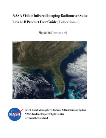
1.0 IntroductionThis document describes the specifications of the NASA-developed Visible Infrared Imaging RadiometerSuite (VIIRS) Level-1B data products. These products are generated and distributed by the NASAVIIRS Science Investigator-led Processing Systems (SIPS) for the Atmosphere, Land, and Oceandisciplines, and are archived at the L1 and Atmosphere Archive & Distribution System (LAADS:https://ladsweb.modaps.eosdis.nasa.gov/) Distributed Active Archive Center (DAAC) at the GoddardSpace Flight Center (GSFC) in Greenbelt, MD. VIIRS is a multidisciplinary instrument that flies aboardthe Suomi National Polar-orbiting Partnership (SNPP) platform, which launched in October 2011, andthe Joint Polar Satellite System (JPSS) satellites, the first of which is JPSS-1 (NOAA-20), that launched inNovember 2017. Three more JPSS satellites are slated for launch between 2021 and 2031(http://www.jpss.noaa.gov/mission and instruments.html).Collection-1 represents the currently operational and publicly available version of the NASA VIIRSLevel-1 products; this User Guide relates to that collection-version. The NASA VIIRS Level-1 productsare implemented in the Network Common Data Format Version 4 (NetCDF4), and NetCDFterminology is used in this document. The NetCDF4 format is also compatible with the HierarchicalData Format Version 5 (HDF5). A hybridized netCDF4–HDF5 approach defines the data format of theVIIRS Level-1 products. This format leverages several individual (extensive use across Earth sciencedisciplines, performance strengths, etc.) as well as collective strengths (extensibility, platformindependence, self-describing nature, etc.) of the two data/file storage formats. Both NetCDF4 andHDF5 software tools can handle these products. For additional format-specific information regardingthe NASA standard VIIRS products, consult the LAADS aq/).SNPP was planned to serve as a bridge mission that provides observation continuity with NASA’s EarthObserving System (EOS) and the operational VIIRS instruments slated for launch aboard the JPSSmission series. A key objective of the VIIRS instrument is to provide data continuity with the EOSModerate Resolution Imaging Spectroradiometer (MODIS). The NASA-developed VIIRS products aredriven by a couple of unique requirements that were part of the 2013 NASA Research Opportunities inSpace and Earth Sciences (ROSES) call specifications. The first required the development of a newLevel-0 to -1B software that would implement the NASA Level-1B calibration approach, using a5
calibration look-up table (LUT) developed and maintained by the NASA VIIRS Characterization SupportTeam (VCST) to generate the VIIRS Level-1B Top-of-Atmosphere (TOA) data product in the heritageMODIS Level-1B format. The second requirement called for the EOS Data and Operations System(EDOS1) to provide the Level-0 data to the SIPSs. NASA helped form the VIIRS Level-1Algorithm/Software Working Group (L1ASWG), which is a confederation of personnel from the VIIRSSIPSs and the VCST, who were mandated to develop this new L0 to L1B software for VIIRS. The firstversion of the VIIRS Level-1 software was completed in October 2015.Consult the following NASA JPSS site for additional VIIRS-specific information onspacecraft/instruments, ground operations, science objectives, 1.1 AcknowledgementsThis User Guide was developed using an earlier version compiled by the NASA Ocean SIPS at GSFC.We appreciate and acknowledge their efforts immensely. We also appreciate the VIIRS Level-1Algorithm/Software Working Group’s efforts and thank them. Thank you also to the NASA VIIRSCharacterization Support Team and the NASA VIIRS Geolcation group for all their help in providingcrucial calibration- and geolcation-specific information, respectively.1.2 Questions/Feedback, etc.If you have any questions regarding the NASA VIIRS Level-1 product, about this User Guide, or havegeneral feedback, please e-mail them to the LAADS User Services: MODAPSUSO@lists.nasa.gov1EDOS, located at GSFC, archives and serves EOS- and SNPP-derived Level-0 reconstructed, unprocessed instrument andpayload data at full resolution with all communication artifacts (e.g., synchronization frames, communication headers,duplicate data, etc.) removed for higher-level data processing by various SIPS and DAAC science data processing systems.6
2.0 VIIRS Instrument Overview2.1 Design and HeritageThe VIIRS instrument is a whiskbroom scanning radiometer whose field-of-view is 112.56º in the crosstrack direction. Orbiting at a nominal altitude of 515 miles (829 km), its swath width is 1901.4 miles(3060 km) and provides full daily daytime and nighttime coverage of Earth. The VIIRS instrument owesits legacy to a number of operational and research instruments that include the following: Advanced Very-high Resolution Radiometer (AVHRR) on NOAA’s Polar-orbitingEnvironmental Satellites (POES). Moderate-resolution Imaging Spectroradiometer (MODIS) on NASA’s Earth Observing System(EOS) Terra and Aqua platforms. Sea-viewing Wide Field-of-view Sensor (SeaWiFS) on GeoEye’s SeaStar satellite. Operational Linescan System (OLS) on Department of Defense’s Defense MeteorologicalSatellite Program (DMSP) satellites.2.2 VIIRS band configuration and related detailsThe VIIRS instrument offers 22 spectral bands that cover the EM spectrum between 0.402 µm and12.49 µm. This range includes 16 moderate-resolution bands (M-bands) that have an at-nadir spatialresolution of 750 meters, 5 image-resolution bands with a spatial resolution of 375 meters at-nadir, anda single panchromatic Day-Night band (DNB) with a spatial resolution of 750 meters across the entirescan. The M-bands comprise 11 Reflective Solar Bands (RSB) and 5 Thermal Emissive bands (TEB),while the I-bands comprise 3 RSBs and 2 TEBs (Table-1). Six of the 11 RSBs are dual-gain reflectivesolar bands, and offer a wider dynamic range to support ocean color applications without saturating thesensor by observing high reflectance targets including land surfaces and clouds. The DNB, with its threegain stages, affords a dynamic range in the order of 107.7
BandWavelength (µm)Spatial Res. At-Nadir (m)GainTEBsRSBsImage-resolution BandsI10.600 – 0.680375SingleI20.846 – 0.885375SingleI31.580 – 1.640375SingleI43.550 – 3.930375SingleI510.50 – 12.40375SingleThermal EmissiveBandsReflective Solar BandsModerate-resolution BandsM10.402 – 0.422750High/LowM20.436 – 0.454750High/LowM30.478 – 0.498750High/LowM40.545 – 0.565750High/LowM50.662 – 0.682750High/LowM60.739 – 0.754750SingleM70.846 – 0.885750High/LowM81.230 – 1.250750SingleM91.371 – 1.386750SingleM101.580 – 1.640750SingleM112.225 – 2.275750SingleM123.660 – 3.840750SingleM133.973 – 4.128750High/LowM148.400 – 8.700750SingleM1510.263 – 11.263750SingleM1611.538 – 12.488750SingleDay-Night band0.500 – 0.900750 [Across entire scan]Low Mid HighTable-1: VIIRS – Wavelength ranges, At-Nadir Spatial Resolution, and Band Gain8
2.3 On-board aggregation, aggregation zones, and bow-tie deletionTo minimize the growth of pixels toward the end of the scan generally observed in data acquired byMODIS, AVHRR and other instruments, VIIRS has implemented a unique method to aggregate pixelsalong the scan. Hence, this renders VIIRS spatial resolutions for nadir and end-of-scan pixels morecomparable. This pixel aggregation is performed on-board for the Earth-view data from single-gain Mbands and the I-bands. Such along-scan aggregations for the dual-gain M-bands are carried out duringground processing to match the on-board single-gain aggregation. The DNB, by design, has nosignificant pixel growth since the DNB CCD array elements are arranged to maintain a near-constant742-m pixel size across an entire scan.To save transmission bandwidth, VIIRS has implemented an on-board process to remove bow-tieobservations that eliminates duplicate pixels in the off-nadir spaces where several pixels from adjacentscans overlap. This on-board processing of the raw data does produce visual artifacts in the Level-1swath and downstream Level-2 products that are removable through interpolation of the samples as partof the geolocation process.2.4 Reflective solar band and Thermal emissive band calibrationTo assure sensor on-orbit calibration, the VIIRS instrument carries a set of on-board calibrators (OBCs),which include a solar diffuser (SD) and a solar diffuser stability monitor (SDSM) primarily used for theRSB calibration and a blackbody (BB) for the TEB. The VIIRS RSB, including the DNB low-gain stage,are calibrated each orbit by a SD panel made of space-grade spectralon placed behind a solar attenuationscreen (SAS). On-orbit changes in SD bidirectional reflectance distribution function (BRDF) areregularly tracked by the SDSM through alternate and near-simultaneous measurements of the sunlight,passing through a fixed attenuation screen, and that reflected off the SD panel. The SDSM has 8detectors (D1-D8), covering wavelengths from 0.41 to 0.93 µm. Similar to MODIS, the VIIRS SDdegradation is strongly wavelength-dependent, with larger degradation at shorter wavelengths. TheSDSM was operated more frequently during the early mission, and then changed to 3 times per week.The RSB detectors signal-to-noise ratio (SNR) are calculated using SD observations over a wide range ofinput signals. The noise characterization performances are monitored on-orbit regularly.9
Using the same strategy developed for MODIS, lunar observations by roll maneuvers have also beenregularly scheduled for VIIRS and used to track its RSB calibration stability. The VIIRS lunarobservations are made through its Space View (SV) port and with Moon phase angles at approximately 51.5⁰. Due to the roll-angle limitation and safety concern for the spacecraft, the lunar observations arescheduled approximately 8 to 10 times each year. In general, the lunar calibration results are consistentwith its SD calibration to within 1.0%.The TEBs are calibrated by an on-board blackbody on a scan-by-scan basis. The temperature-controlledBB is monitored by 6 embedded thermistors traceable to National Institute of Standards and Technology(NIST), and protected by a shield plate from stray light. During instrument nominal operations, the BBtemperature is controlled at 292.7 K. On a quarterly basis, a BB warm-up and cool-down (WUCD)operation is performed with its temperatures varying between 267 K (the instrument ambient) and 315K. The data collected during BB WUCD have been used to monitor on-orbit changes in TEB detectors’offset and nonlinear calibration coefficients. The TEB detectors noise characterization is performedusing BB WUCD data at different temperatures (radiances) in terms of noise equivalent temperaturedifferences (NEdT).2.5 Uncertainty IndexThe uncertainty index (UI) in the L1B SDS layer holds an 8-bit integer for each pixel. These integersrepresent the estimate of the uncertainty in each measurement of reflectance for the reflective solarbands and radiance for the TEBs and DNB [1][2][3]. A fill-value of -1 is set when observation data ismissing or when the data cannot be calibrated. The indices take on values of 0 through 127. A value of127 represents a 100% uncertainty value or above. The L1B computes and reports the UncertaintyIndex corresponding to the measured percent uncertainty, and is derived from the uncertainty indexthrough the formula:Uncertainty in percent 1.0 scaling factor * UI 2The scaling factor values for all the bands are the same per L1B design. The attributes are provided forconvenience to those downstream users who convert the uncertainty index to percent uncertainty.10
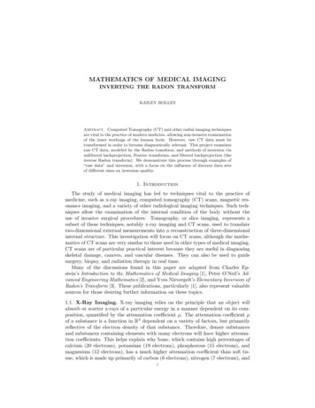
3.0 NASA VIIRS Level-1 Processing FlowThe NASA VIIRS Level-1 software and data products largely follow the model previously developed forMODIS: The software includes separate executable modules for Level-1A, Geolocation, OnboardCalibrator (OBC) and Level-1B processing. The Level-1A product provides the input to the Geolocation, Level-1B and OBC software. The nominal temporal duration of the NASA-developed VIIRS L1 granule is 6-minutes (360seconds) in contrast to a NOAA VIIRS granule, which is 85.35 seconds.The VIIRS Level-1 processing flow is illustrated in Figure-1, which shows the processing softwaremodules, input data types (raw, dynamic ancillary, static ancillary), look-up tables (LUTs) and dataproducts.Figure-1: NASA VIIRS Level-1 Processing Flow11
EDOS delivers the VIIRS Level-0 and SNPP spacecraft data in the form of Production Data Sets (PDS).A session-based PDS (S-PDS) contains instrument or spacecraft packet data for a single downlink(approximately 1 orbit), while a time-based PDS (T-PDS) contains data for a specified time period thatspans 2 hours. The PDS formats are specified in Reference [6], and that of the VIIRS packets inReference [5].The VIIRS Level-1 data products follow the standard NASA EOS definitions for product levels, asspecified in Reference [4]. Given the requirement to archive them at EOSDIS DAACs, they includestandard processed data products along with their granule metadata. The metadata for the VIIRS Level-1data products are stored as NetCDF4/HDF5 attributes. The granule-level metadata are stored asattributes at the file-level, while the object-level metadata are stored using attributes attached to theindividual data objects. An Interface Control Document (ICD) describes the SNPP Science DataSegment elements, specific to each SIPS’ processing and distribution responsibilities, and theirinterfaces in Reference [7].As stated above, a VIIRS granule’s temporal duration is specified to last exactly 6 minutes, which issynchronized with the UTC (Coordinated Universal Time) day. This was chosen at the request of theVIIRS Atmosphere team for compatibility with the Cross-track Infrared Sounder (CrIS) data products;CrIS is also flown on SNPP. The granulation of the VIIRS data is performed during the Level-1Aprocessing, with each granule containing all the VIIRS scans that start within the granule period.The same Level-1 software is installed at all three VIIRS discipline SIPSs (i.e., Atmosphere, Land, andOcean) that each produce domain-specific higher-level products. VIIRS atmosphere products generatedby the Atmosphere SIPS at the Space Science and Engineering Center (SSEC), University of Wisconsin,Madison are transmitted to LAADS for archiving and distribution. VIIRS land products generated byLand SIPS at GSFC are transmitted to the Land Processes DAAC in Sioux Falls, SD for archiving anddistribution. VIIRS ocean products generated by the Ocean SIPS are archived and distributed by theOcean Biology DAAC at GSFC. VIIRS Level-1 products are produced by Land SIPS, and archived anddistributed via LAADS; both entities are located within GSFC.12
This User Guide primarily attempts to describe the data structure and contents of the following two setsof VIIRS Level-1 Geolocation (Section 3.0) and Level-1B calibrated radiance products (Section 4.0);each set contains three products (Table-2):ESDT Short-nameLong-nameVNP03IMGVIIRS/NPP Imagery Resolution Terrain Corrected Geolocation 6-Min L1 Swath 375mVNP03MODVIIRS/NPP Moderate Resolution Terrain Corrected Geolocation 6-Min L1 Swath 750mVNP03DNBVIIRS/NPP Day/Night Band Resolution Terrain Corrected Geolocation 6-Min L1 Swath 750mVNP02IMGVIIRS/NPP Imagery Resolution 6-Min L1B Swath 375mVNP02MODVIIRS/NPP Moderate Resolution 6-Min L1B Swath 750mVNP02DNBVIIRS/NPP Day/Night Band 6-Min L1B Swath 750mTable-2: NASA VIIRS L1 Geolocation and L1B Calibrated Radiance products4.0 Level-1 Geolocation Data ProductThe VIIRS Geolocation data product contains the geographical coordinate locations, i.e., the latitudesand longitudes for every pixel location/observation, and related data including sensor and solar zenithand azimuth angles, height, range, land/water mask, and quality flags. Separate products exist for eachresolution (I-band, M-band, Day-Night Band (DNB)). These products, in netCDF4/HDF5 format, arestored in the following three data groups: geolocation data, navigation data andscan line attributes. These names reflect the exact style (i.e., lower-case, underscores, etc.) asencoded in the netCDF metadata. The following tables provide detailed specifications of the variablesunder each of these three groups.4.1 geolocation dataTable-3 specifies the geolocation Science Data Set (SDS) variables within the 375-m VNP03IMGgeolocation product, whose image dimensions are 6464 rows by 6400 pixels.13
SDS layerUnitsBit-typeFill-valueValid rangeScale factorTerrain height at pixelmeters16-bit integer-32768Max 100001.0locationsLand/Water mask atMin -1000NA8-bit unsigned integer255pixel locationsLatitudes of pixeldegrees north32-bit floating point-999.9Max 90.0NAMin -90.0degrees east32-bit floating point-999.9locationsGeolocation pixelNA4, 5, 6, 7*locationsLongitudes of pixelFlag values 0, 1, 2, 3,Max 180.0NAMin -180.0NA8-bit unsigned integerNAFlag masks 1, 2**NAmeters16-bit integer-32768Max 32767100.0quality flagsSatellite-to-pixel rangeMin 0Sensor azimuth angledegrees16-bit integer-32768at pixel locationsSensor zenith angle atdegrees16-bit integer-32768Max 180000.01Min 0degrees16-bit integer-32768pixel locationsSolar zenith angle at0.01Min -18000pixel locationsSolar azimuth angle atMax 18000Max 180000.01Min -18000degrees16-bit integer-32768pixel locationsMax 180000.01Min 0* Land-water mask flag meanings: 0 Shallow Ocean, 1 Land, 2 Coastline, 3 Shallow Inland, 4 Ephemeral, 5 Deep Inland, 6 Continental, 8 Deep Ocean** Geolocation pixel quality flag meanings: 1 Earth intersection, 2 Sensor zenithTable-3: Geolocation SDS variables in the 375-m VNP03IMG geolocation productTable-4 outlines the geolocation SDS variables in the 750-m VNP03MOD geolocation product whoseimage dimensions are 3232 lines by 3200 pixels.14
SDS layerUnitsBit-typeFill-valueValid rangeScale factorTerrain height at pixelmeters16-bit integer-32768Max 100001.0locationsLand/Water mask atMin -1000NA8-bit unsigned integer255pixel locationsLatitudes of pixeldegrees north32-bit floating point-999.9Max 90.0NAMin -90.0degrees east32-bit floating point-999.9locationsGeolocation pixelNA4, 5, 6, 7*locationsLongitudes of pixelFlag values 0, 1, 2, 3,Max 180.0NAMin -180.0NA8-bit unsigned integerNAFlag masks 1, 2, 4**NAmeters16-bit integer-32768Max 32767100.0quality flagsSatellite-to-pixel rangeMin 0Sensor azimuth angledegrees16-bit integer-32768at pixel locationsSensor zenith angle atdegrees16-bit integer-32768Max 180000.01Min 0degrees16-bit integer-32768pixel locationsSolar zenith angle at0.01Min -18000pixel locationsSolar azimuth angle atMax 18000Max 180000.01Min -18000degrees16-bit integer-32768pixel locationsMax 180000.01Min 0* Land-water mask flag meanings: 0 Shallow Ocean, 1 Land, 2 Coastline, 3 Shallow Inland, 4 Ephemeral, 5 Deep Inland, 6 Continental, 7 Deep Ocean** Geolocation pixel quality flag meanings: 1 Input invalid, 2 Pointing bad, 4 Terrain badTable-4: Geolocation SDS variables in the 750-m VNP03MOD geolocation productTable-5 specifies the geolocation SDS variables within the 750-m VNP03DNB geolocation product,whose image dimensions are 3232 rows by 4064 pixels.15
SDS layerUnitsBit-typeFill-valueValid rangeScale factorTerrain height at pixelmeters16-bit integer-32768Max 100001.0locationsLand/Water mask atMin -1000NA8-bit unsigned integer255pixel locationsLatitudes of pixeldegrees north32-bit floating point-999.9degrees east32-bit floating point-999.9degrees16-bit integer-32768Max 180.0NAMax 180000.01Min -18000degrees16-bit integer-32768locationsMoon illuminationNAMin -180.0locationsLunar zenith at pixelMax 90.0Min -90.0locationsLunar azimuth at pixelNA4, 5, 6, 7*locationsLongitudes of pixelFlag values 0, 1, 2, 3,Max 180000.01Min 0percent16-bit integer-32768fraction at pixelMax 100000.01Min 0locationsMoon phase angle atdegrees16-bit integer-32768pixel locationsGeolocation pixelMax 180000.01Min 0NA8-bit unsigned integerNAFlag masks 1, 2, 4**NAmeters16-bit integer-32768Max 32767100.0quality flagsSatellite-to-pixel rangeMin 0Sensor azimuth angledegrees16-bit integer-32768at pixel locationsSensor zenith angle atdegrees16-bit integer-32768Max 180000.01Min 0degrees16-bit integer-32768pixel locationsSolar zenith angle at0.01Min -18000pixel locationsSolar azimuth angle atMax 18000Max 180000.01Min -18000degrees16-bit integer-32768pixel locationsMax 180000.01Min 0* Land-water mask flag meanings: 0 Shallow Ocean, 1 Land, 2 Coastline, 3 Shallow Inland, 4 Ephemeral, 5 16
Deep Inland, 6 Continental, 7 Deep Ocean** Geolocation pixel quality flag meanings: 1 Earth intersection, 2 Sensor zenithTable-5: Geolocation SDS variables in the 750-m VNP03DNB geolocation product4.2 navigation dataThe navigation data group contains the ephemeris and attitude data for each scan, along with inputvalues for additional information used in geolocation (Sun and Moon vectors). Table-5 below providesdetailed specifications of the navigation-related variables for the 375-m I-band, and 750-m M-band andDNB products.SDS layerUnitsBit-typeFill-valueValid rangeScale factorAttitude angles (roll,degrees32-bit floating point-999.9Max 180.0NApitch, yaw) at EV end-Min -180.0timesAttitude angles (roll,degrees32-bit floating point-999.9pitch, yaw) at EV mid-Max 180.0NAMin -180.0timesAttitude angles (roll,degrees32-bit floating point-999.9pitch, yaw) at EV start-Max 180.0NAMin -180.0timesAttitude quaternions atNA32-bit floating point-999.9EV mid-times (J2000 toMax 1.0NAMin -1.0spacecraft)Earth-Moon distancemeters32-bit floating point-999.9Max 4.2E8NAMin 3.5E8Earth-Sun distanceAU32-bit floating point-999.9Max 1.02NAMin 0.98Lunar unit vectors inNA32-bit floating point-999.9VIIRS frameLunar unit vectors inNAMin -1.0NA32-bit floating point-999.9J2000 frameOrbit position vectors atMax 1.0Max 1.0NAMin -1.0meters32-bit floating point17-9999999.0Max 7300000.0NA
EV end-times (ECR)Orbit position vectors atMin -7300000.0meters32-bit floating point-9999999.0EV mid-times (ECR)Orbit position vectors atmeters32-bit floating point-9999999.0meters/second 32-bit floating point-9999999.0meters/second 32-bit floating point-9999999.0meters/second 32-bit floating point-9999999.0NAMax 7600NAMax 7600NAMin -7600NA32-bit floating point-999.9VIIRS frameSolar unit vectors inMax 7600Min -7600EV start-times (ECR)Solar unit vectors inNAMin -7600EV mid-times (ECR)Orbit velocity vectors atMax 7300000.0Min -7300000.0EV end-times (ECR)Orbit velocity vectors atNAMin -7300000.0EV start-times (ECR)Orbit velocity vectors atMax 7300000.0Max 1.0NAMin -1.0NA32-bit floating point-999.9J2000 frameMax 1.0NAMin -1.0Table-6: Navigation SDS variables in the 375-m VNP03IMG, 750-m VNP03MOD andVNP03DNB geolocation products4.3 scan line attributesThe scanline attributes group within the geolocation product contain a number of scan-level data objectsfor all channels that are described in the following table.SDS layerUnitsBit-typeFill-valueValid rangeScale factorEarth view mid timeseconds64-bit floating point-999.9Max 2.0E9NA(TAI93)Half-angle mirror sideMin 0.0NA8-bit unsigned integer255Max 1NAMin 0Scan end time (TAI93)seconds64-bit floating point-999.9Max 2.0E9NAMin 0.0Geolocation scan qualityNA16-bit integer-999.918Flag masks 1, 2, 4, 8,NA
flags16, 32, 64, 128*Scan start time (TAI93)seconds64-bit floating point-999.9Max 2.0E9NAMin 0.0VIIRS sensor modeNA8-bit unsigned integer255Flag values 0, 1, 2, 3,NA4, 5, 6*** Geolocation scan quality flag meanings: 1 SCE side A B, 2 SCE side invalid, 4 Sector rotation, 8 Encoder degraded, 16 SAA, 32 Solar eclipse, 64 Lunar eclipse, 128 HAM side** VIIRS sensor mode flag meanings: 0 Launch, 1 Activation, 2 Outgas, 3 Diagnostic, 4 Day, 5 Night, 6 SafeTable-7: Scanline SDS variables in the 375-m VNP03IMG, 750-m VNP03MOD and VNP03DNBgeolocation products5.0 Level-1B Earth-View ProductsThe VIIRS Level-1B product contains calibrated radiance values, quality flags, uncertainty indices, andan array of related information that are contained in three data groups: observation data,scan line attributes, and diagnostics; data exist in separate products for each resolution (I-bands, Mbands, and DNB). What follows are detailed specifications of the variables for each data group. Adetailed description of the quality flags and a comparison with the current IDPS SDR flags is provided inAppendix-A.5.1 observation dataThe obs
Level-1B Product User Guide [Collection-1] May 2018 [Version 1.0] Level-1 and Atmosphere Archive & Distribution System NASA Goddard Space Flight Center . Observing System (EOS) and the operational VIIRS instruments slated for launch aboard the JPSS mission series. A key objective of the VI