Transcription
An introduction to well interventionSPE Aberdeen monthly evening meetingJim Wright, The Douglas Hotel, 25th January 2011 2009 Aker Qserv Ltd
Industry sector contextOil Oil production continues to grow Western Europe and NorthAmerica mature basins inproduction decline Reduction in discovery rates “Easy” giant fields are nowmature Peak Oil Generally predicted on accessiblereserves today. Does not cater for new technologyand demand Previously inaccessible deepwaterreservoirs shall be tappedSlide 2 2009 Aker Qserv Ltd
Industry sector contextGas Gas production continues to grow Eastern Europe & FSU dominatemarket Potential peak is much later thanoil Bridge carbon based energy supplyto renewable Abundance of natural gas Cleaner energy2011 UKCS Exploration activity fell to lowestlevel since 1960’s Only five new fields came onstream (smallest annual addition inUKCS history)Slide 3 2009 Aker Qserv Ltd
What is well intervention?Well intervention An operation carried out on an oil or gas well to extend its producing life byimproving performance or providing access to stranded or additionalhydrocarbon reserves Typical interventions services include, WirelineTractorsCoiled TubingHydraulic WorkoverSlide 4 2009 Aker Qserv Ltd
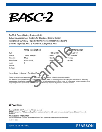
WirelineHistory Mechanical slickline was formerlyknown as measuring line Flat tape with depth increments Schlumberger brothers consideredthe inventors of electric logging in1927.Slide 5 2009 Aker Qserv Ltd
WirelineSlickline wireNominal diameterMaterial / TypeBreaking strainRemarks0.108”UHT CarbonSupa 752730 lbs2100 lbsPoor corrosive resistanceSour gas applications0.125”UHT CarbonSupa 753665 lbs2700 lbsPoor corrosive resistanceSour gas applications7/32”ConventionalDyform5400 – 6010 lbs6500 – 8370 lbsDyform 00 – 13,490 lbs13,560 – 17550 lbsVery high breaking forcegives the operator bettermargins when carrying outfishing operations.Braided wireElectric line wire7/32” Poly cableMono conductor cablewidely used for e-lineoperationsTypically 5200 lbsCable type will depend ofwell conditions and operationconducted5/16” Poly CableCommonly used forlogging and perforatingTypically 11,000 lbsCerberus modelling withdetermine wire selection.Slide 6 2009 Aker Qserv Ltd
WirelineSlickline applicationsElectric line applications Gauge Cutter / Centraliser runs. Provides real time communication from(Establish the well bore is clear fromrestriction)well to surface Unparalleled depth control Setting / Pulling plugs Setting / Pulling gas lift valves Bailing sand and debris Bottom hole pressure and temperature LoggingBallistic operationsZonal isolationWell integritysurveys. (Memory) Shifting sleevesBraided line applications Utilised where additional pulling force isrequired: Fishing operations Conveying heavy toolstrings Deeper accessSlide 7 2009 Aker Qserv Ltd
WirelineUnit components - SlicklineWinchUnitWirelineMastBottomSheaveSlide 8Measuringhead 2009 Aker Qserv Ltd
WirelinePrimary Well controlStuffing Box (Slickline) Grease Head (Braided/Electric line) Secondary Well control BOP c/w Dual blind rams Slickline BOP c/w inverted dual blind rams Braided/Electric line Grease injection between ramsTertiary Well control BOP c/w Shear Ram In the event tree MV cannotshear wireSlide 9 2009 Aker Qserv Ltd
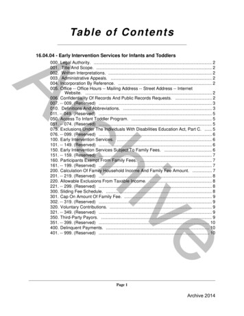
TractorsHistory Deviated or horizontal wells nowcommon place Slickline relies on gravity forwell access Tractors introduced in 1996 Provides driving force at theend of the wire via tractionwheels Speed and force dictated bynumber of drive sections Mechanical Services introduced in2003Coiled Tubing Tractorsgo to "View". "Header and Footer"to edit this textSlide 10 2009 Aker Qserv Ltd
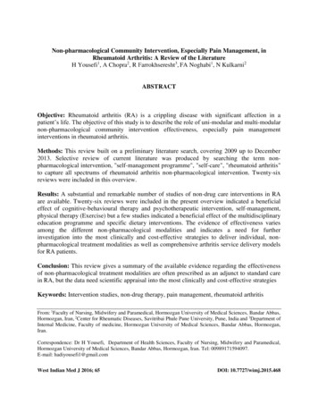
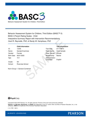
TractorsHistoryWireline Tractor IntroductionMechanical Services Introduction160Operations per year1401201008060402001992 1993 1994 1995 1996 1997 1998 1999 2000 2001 2002 2003 2004 2005 2006 2007 2008 2009 2010 2011Tractor* ImagesCoilSnubbingand text courtesy of StatoilSlide 11 2009 Aker Qserv LtdRLWI
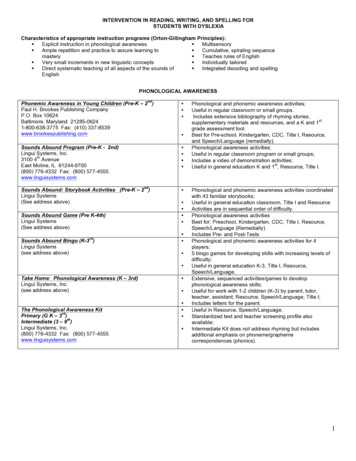
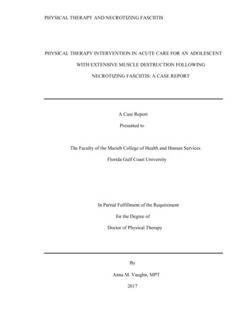
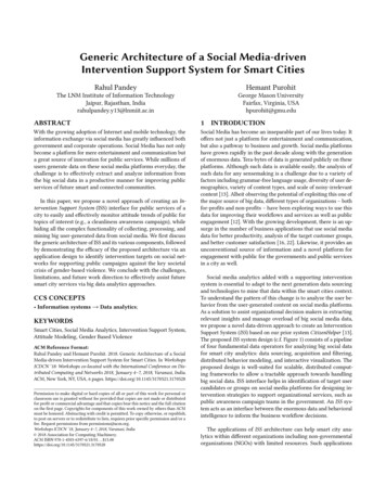
TractorsUnit components Electrics Powered from surface through wire Control for motor & pump Motor & Pump Generates hydraulic flow and pressure Wheel section Provides axial force at end of wire Typically 500lbs per section Compensator Caters for oil pressure increase and keeps pump primedElectronicsMotor & pumpSlide 12 2009 Aker Qserv LtdWheel SectionCompensator
TractorsApplications Well access Mechanical applications introduced in2003 Scale milling Brushing and polishing Manipulation tools Debris removal Logging while Tractoring Bi-directional Open hole tractorSlide 13 2009 Aker Qserv Ltd
Coiled tubingHistory Pipeline Under The Ocean(PLUTO) Allied invasion in 1944 3in pipelines, 70km long Supplied fuel to allies in Europe 1st oilfield application in 1962 15,000ft, 1.315in OD Sand bridge cleanoutsSlide 14 2009 Aker Qserv Ltd
Coiled tubingApplications Vertical, deviated and horizontalwells on both land and offshore: Fluid displacementLoggingPerforatingStimulationRemedial cementingSetting, retrieving bridge plugsFishingMechanical removal of blockages(milling) .plus much more!!Slide 15 2009 Aker Qserv Ltd
Coiled tubingUnit ryEquip,TubingReelSlide 16 2009 Aker Qserv Ltd
Coiled tubingCoiled tubing string design Continuous length of pipe 1 1/2” – 3 ½” OD Typically 22,000ft long Tapered ID design To withstand combination of forcesin hole Adequate stiffness “lock-up” Plastic deformation consideration Circulation rates and pressures Logistic considerationsSlide 17 2009 Aker Qserv Ltd
Tubing guide arch & injector headFunction To support, straighten and align thetubing into the injector head Provides the surface drive force to runand retrieve the tubingDesign Consideration Arch radius should be at least 30 timestubing OD (API 5C7) Must withstand the loading caused byreel back tension Must withstand side loading caused byfleet angle 120% of max force expected pull thetubing from the well (API 5C7) 120% of max force expected to snub thetubing into the well against wellheadpressure (API 5C7)Slide 18 2009 Aker Qserv Ltd
Pressure control equipment (PCE)Function Stripper provides dynamic primary sealaround the tubing during tripping and astatic seal around the CT when there isno movement BOP provides secondary wellborepressure containment and facilitatestubing severance, tubing support andseals around the tubingDesign Consideration Rated working pressure must exceedmaximum anticipated surface pressure Stack-up height. Ram configuration tosuit application Pipe severance under anticipatedconditionsSlide 19 2009 Aker Qserv Ltd
Hydraulic Workover (HWO)History Mr R H.C. Otis Snr. designed andbuilt first unit to run pipe underpressure in 1929 Rig “snubbed’ pipe in via series ofchains and pulleys 1st generation HWO unit introducedin the 1960’s. No requirement for rig Typically run pipe in singles Rig assist (RA) units returned inlate 1990’s to support UBD activity Hydraulic jacksSlide 20 2009 Aker Qserv Ltd
Hydraulic Workover (HWO)Applications Through tubing intervention –washing, unloading, stimulation etc.etc. Milling inside tubing or casing Running or pulling productionstrings Through tubing drilling (over orunder balanced) Abandonment Deploying perforating guns underpressure Blowout recovery operationsSlide 21 2009 Aker Qserv Ltd
Hydraulic Workover (HWO)Unit components Ginpole & winch Facilitates a crane boom Picks up tubing joints to the workbasket Not required for Rig Assist Units Travelling Slips Two sets of slips to cater for pipeheavy and light scenarios Incorporates rotary head Work Basket Accommodates crew and unitcontrolsSlide 22 2009 Aker Qserv Ltd
Hydraulic Workover (HWO)Unit components Hydraulic jack Provides the appropriate forceto run and pull tubing string Typically 600klbs Stationary slips Holds tubing string whentravelling slips are disengaged Annular BOP Secondary well control whenstripping/snubbing pipe Stripper 1 & 2 Primary well control whensnubbing/stripping pipe Equalising loop for runningupset joints/collars BOP’s Tertiary well control Pipe/Blind/PipeSlide 23 2009 Aker Qserv Ltd
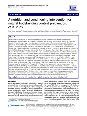
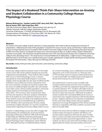
Hydraulic Workover (HWO)The stripping process# 2 closed - LowerTool JointLower Tool JointClose #1Close # 2EqualizeSlide 24 2009 Aker Qserv LtdBleed Off PSIOpen # 2Open # 1 & LowerTool Joint
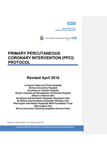
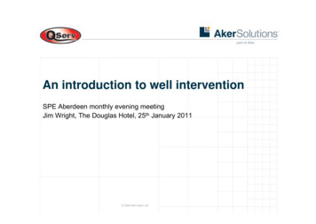
HeavierService positioningHWOIntervention classRA UnitCoiled tubingE-lineTractorLighterHD fishingSlicklineLowerIntervention cost Slide 25 2009 Aker Qserv LtdHigher
Recent/Future developmentsHeavierSubseaDevelopment of service units Conveyance challenges Fatigue managementReal time dataDigital slickline Real time coiled tubingProduct development Well integrity/abandonment Composite SL and CTRig (CATB)LWI (CATA)Lighter Rig (CATC)Intervention class Cat B – heavy intervention rigs Cat A – intervention mono hullvesselsRLWI (CAT A)Lower Lighter, less frictionRiserless coiled tubing Memory Tractor Slide 26 2009 Aker Qserv LtdIntervention cost Higher
Copyright and disclaimerCopyright of all published material including photographs, drawings and images in this document remains vested inAker Solutions and third party contributors as appropriate. Accordingly, neither the whole nor any part of this documentshall be reproduced in any form nor used in any manner without express prior permission and applicableacknowledgements. No trademark, copyright or other notice shall be altered or removed from any reproduction.This Presentation includes and is based, inter alia, on forward-looking information and statements that are subject torisks and uncertainties that could cause actual results to differ. These statements and this Presentation are based oncurrent expectations, estimates and projections about global economic conditions, the economic conditions of theregions and industries that are major markets for Aker Solutions ASA and Aker Solutions ASA’s (including subsidiariesand affiliates) lines of business. These expectations, estimates and projections are generally identifiable by statementscontaining words such as “expects”, “believes”, “estimates” or similar expressions. Important factors that could causeactual results to differ materially from those expectations include, among others, economic and market conditions inthe geographic areas and industries that are or will be major markets for Aker Solutions’ businesses, oil prices, marketacceptance of new products and services, changes in governmental regulations, interest rates, fluctuations in currencyexchange rates and such other factors as may be discussed from time to time in the Presentation. Although AkerSolutions ASA believes that its expectations and the Presentation are based upon reasonable assumptions, it can giveno assurance that those expectations will be achieved or that the actual results will be as set out in the Presentation.Aker Solutions ASA is making no representation or warranty, expressed or implied, as to the accuracy, reliability orcompleteness of the Presentation, and neither Aker Solutions ASA nor any of its directors, officers or employees willhave any liability to you or any other persons resulting from your use.Aker Solutions consists of many legally independent entities, constituting their own separate identities. Aker Solutionsis used as the common brand or trade mark for most of these entities. In this presentation we may sometimes use“Aker Solutions”, “we” or “us” when we refer to Aker Solutions companies in general or where no useful purpose isserved by identifying any particular Aker Solutions company.Slide 27 2009 Aker Qserv Ltd
Tubing guide arch & injector head Function To support, straighten and align the tubing into the injector head Provides the surface drive force to run and retrieve the tubing Design Consideration Arch radius should be at least 30 times tubing OD (API 5C7) Must withstand the loading caused by reel back tension