Transcription
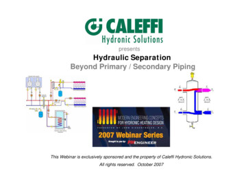
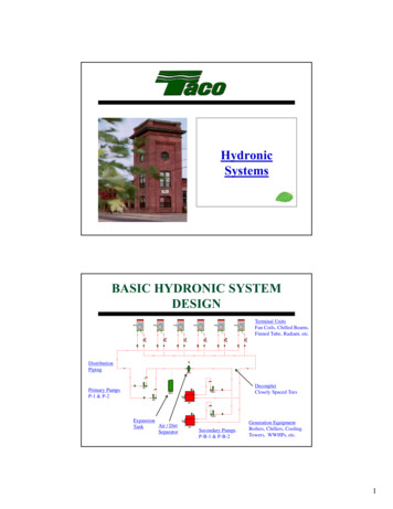
HydronicSystemsBASIC HYDRONIC SYSTEMDESIGNFCUFCUFCUDistributionPipingPrimary PumpsP-1 & P-2FCUFCUFCUTerminal UnitsFan Coils, Chilled Beams,Finned Tube, Radiant, etc.AS-1P-1P-B-1ET-1DecouplerClosely Spaced TeesP-2B-1P-B-2ExpansionAir / DirtTankSeparatorB-2Secondary PumpsP-B-1 & P-B-2Generation EquipmentBoilers, Chillers, CoolingTowers, WWHPs, etc.1
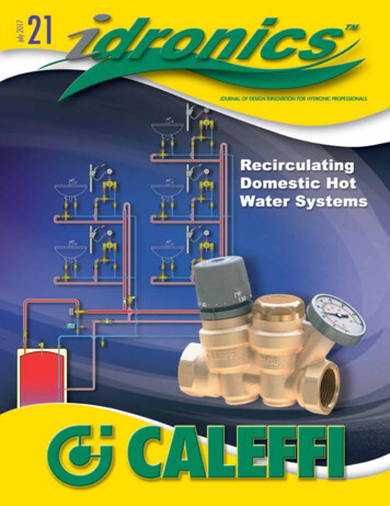
REFERRING TO -2PrimaryPumpsCOOLINGAIR/DIRT SEPARATORS Air Vents at High PointsReduce Fluid VelocityChange Fluid DirectionReduce Pressure (Tangential)Coalescence (Microbubble)2
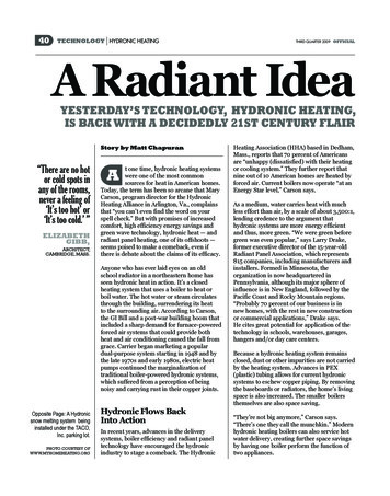
EXPANSION TANKS Control pressure, control problems Expansion tanks control thermal expansion andcontraction of system fluidz Establish the point of “no pressure change”.Full AcceptanceBladder typePartial AcceptanceBladder typePartial AcceptanceDiaphragm typeCENTRIFUGAL PUMPCOMPONENTSBearing FrameAssemblyMotorCasing / VoluteDischargeSuctionDrain PanCoupler w/GuardBase3
CENTRIFUGAL PUMPCOMPONENTSImpellerBearing FrameAssemblyWoods Dura-FlexCouplerMotorMechanicalSealPump ShaftMotor ShaftCOUPLERWoods Dura-Flex Coupler4
BEARING ASSEMBLYBearing Frame AssemblyMECHANICAL SEALImpellerCoverStationarySeatPump ShaftSlip-on Shaft SleeveRotating ElementJohn Crane (Type 21) mechanical seal5
END SUCTION PUMPS End Suction PumpszzzMost Popular StyleSuction / Discharge at 90ºSplit coupled allows servicing without disturbingpipe connectionsBase Mounted, Split CoupledFoot Mounted, Close CoupledIN-LINE PUMPS In-Line Pumpsz Suction / Discharge are In-Linez Differentiated by shaft orientationz Pipe supported, not fixed to structureHorizontal In-LineVertical In-Line6
SPLIT CASE PUMPS Split Casez Two sets of bearings to support shaftz Allows Access to both seals without moving motor ordisturbing pipingz Up to 1,500 HPHorizontal Split CaseVertical Split CaseVERTICAL TURBINES Vertical Lineshaft Turbine Designed to Lift Liquid from Sump / Tank Motor and Impeller are separated Impellers “Push” better than “Pull” Cooling Tower Sumps7
NEW “SMART” PUMPS Speed varies without sensors High Efficiency ECMzzElectronically Commutated MotorA.k.a. DC Brushless Motor Integral VFD Sophisticated Electronics Residential to Light CommercialTYPICALCAPACITIESTYPEGPMHD (FT.)HPRPM20 - 37510 - 75¼-31760, 3500END SUCTION40 – 4,00010 - 400⅓ - 2001160, 1760, 3500VERTICAL IN-LINE40 – 12,00010 - 400¼ - 6001160, 1760, 3500SPLIT CASE100 – 18,00020 - 5003 – 1,5001160, 1760, 350020 – 6,00010 - 150½ - 1501160, 1760HORIZ. IN-LINEVERTICAL TURBINE8
CENTRIFUGAL PUMPFUNCTION Pumps create Differential Pressure (ΔP) Water Flows From Higher Pressure to Lower Pressure The ΔP Induces Flow Against System Resistance In an Open System the ΔP also Induces Lift AgainstAtmospheric Pressure and GravityCENTRIFUGAL PUMPBASIC OPERATION Impeller spin accelerates the liquid radiallyLiquid forced to the outside of the impellerCutwater diverts liquid out through the dischargeImpeller eye is point of lowest pressureDischargeSuctionImpellerCutwater9
CENTRIFUGAL PUMPSAFFINITY LAWSThe Pump Affinity Laws are a series of relationshipsrelating:Flow (GPM)Head (HEAD)Horsepower (BHP)RPM Speed (RPM)Impeller Dia. (DIA)Allow designers to estimate pump performance underdifferent conditionsAFFINITY LAW #1 GPM varies with RPM Pump speeds up, flow increases Pump slows down, flow decreases GPM varies with DIA Large diameter impellers move more flow Small diameter impellers move less flow10
AFFINITY LAW #11760 RPM60 Hz1170 RPM40 Hz580 RPM20 HzAFFINITY LAW #2 HEAD varies as the square of the RPM Pump speeds up, head increases exponentially Pump slows down, head decreases exponentially11
AFFINITY LAW #2AFFINITY LAW #3 BHP* varies as a cube of RPM Pump speeds up, BHP increases by cube Pump slows down, BHP decreases by cubeBHP Brake Horsepower is the actual power required to rotate the pumpshaft. It is the portion of the motor HP that does the work.12
AFFINITY LAWSReducing Speed by Half:Change in RPM(or DIA)Change inGPMChange inHEADChange in BHPx 1/2x 1/2x 1/4x 1/8Change in RPM(or DIA)Change inGPMChange inHEADChange in BHPx2x2x4x8Doubling Speed:AFFINITY LAWSHow much HP is required to operate a 100 HP, 1760 RPMmotor at half speed?13
AFFINITY %56%42%50%50%25%12.5%25%25%6%1.2%“Getting Into the Flow”“the application of VFDs toconstant speed pumps is now thefastest growing segment of thecommercial pumping industry, atrend that improves (system)performance and efficiency ”14
WHY VFDs on PUMPS Soft Start Same cost as a motor starter Gentler on motors Reduces inrush current Balancing without multi-purpose valve Significant energy saving opportunity Variable Flow Flow varies according to demand Ultimate energy savingsPump Curves15
Pump CurvesPUMP CAN ONLY OPERATE ON ITS CURVE13”12”200IMPELLER CURVES11”10”HEAD(FT)10010 020 030 040 050 060 070 0FLOW (GPM)System Curve200FLOW HEAD²( Y X² )HEAD(FT)100SYSTEM CURVE(PARABOLA)10 020 030 040 050 060 070 0FLOW (GPM)16
Horsepower CurvesPUMP OPERATES WHERE SYSTEM AND IMPELLER CURVES INTERSECT10IMPELLER CURVE1520HP CURVES200OPERATING POINTHEAD(FT)100SYSTEM CURVE(PARABOLA)10 020 030 040 050 060 070 0FLOW (GPM)Parallel PumpingCorrect SelectionGPM IS ADDITIVE, HEAD REMAINS THE SAMESYSTEMCURVE2002 PUMPS ONOPERATING POINT1001 PUMP ONOPERATING POINTIMPELLER CURVESP1 or P2STATICHEAD10 020 030 0P1 P240 050 060 017
Parallel PumpingIncorrect SelectionGPM IS ADDITIVE, HEAD REMAINS THE SAMESYSTEMCURVE2002 PUMPS ONOPERATING POINTP1 or P2100P1 P2IMPELLER CURVESOne pump running does notintersect with system curveResult No FlowSTATICHEAD10 020 030 040 050 060 0Hydronic Piping Systems Direct Return SystemReverse Return SystemPrimary-Secondary Pumping SystemInjection Pumping SystemSeries Pump SystemZone Pumping SystemSingle Pipe System18
Direct Return (First In/First Out) Advantages Shorter Pipe Runs Lower first cost Lower pump head DisadvantageszPoor Comfort Does not insure adequate flow to all terminal unitszNot Self Balancing Balance valves and balancing requiredReverse Return(First In/Last Out) Advantages Improved Comfort Greater assurance ofadequate flow to allterminal units all times Self Balancing Disadvantages Longer Pipe Runs Higher first cost Higher pump head19
Primary-Secondary Advantages Improved Comfort Reduced complexityof balancing Lower OperatingCost Reduced pump horsepower by separating zones withdifferent loads, operating temperatures, or pipe length Disadvantages Increased Number of Pumps and First CostDECOUPLINGDistance Between Tees as Short as Possible (Tee to Tee).Pressure Drop Between Tees Will Determine Flow in SecondaryCircuit when Secondary Pump is OffWATER ALWAYS FOLLOWS PATH OF LEAST RESISTANCE20
Single Pipe AdvantageszMaximum Comfort Insures adequateflow to all terminalunits at all timesz Self balancingzLower First Cost Eliminate controlvalves, balance valves, balancing, pipe and fittings DisadvantageszRequires accounting for temperature cascade toprovide adequate capacity of terminal units.Injection Pumping Advantages z Lower OperatingCost Operate secondarysystems at optimumoperatingtemperatures z Lower First Cost Use one primary boiler system for multiple secondarysystems requiring different operating temperatures. Disadvantages z Increased Number of Pumps and First Cost21
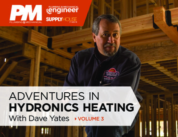
Injection Pumping –Another Look!Zone LoopInjectionBuildingLoopSeries Pumping System AdvantageszLower OperatingCost Reduced pumphorsepower byseparating zoneswith different loads30000 BTU/H6.4 GPM100 F6.4 GPM7 FT110 FIHL-140000 BTU/H8.5 GPM8.5 GPM7 FTIHL-2140 F180 FP-3120000 BTU/H6.4 GPM160 F5.3 GPM7 FT180 FIHL-36.4 GPM12 FTP-1100 F110 F50000 BTU/H5.3 GPMP-2P-4B-1 DisadvantageszzIncreased Number of Pumps and First CostOperation of Pumps Affects Flow in Other Circuitsz Pumps are not decoupledz Increased complexity of balancing22
Zone Pumping Advantagesz30000 BTU/H6.4 GPMLower OperatingCost Reduced pumphorsepower byseparating zoneswith different loads100 F6.4 GPM12 FT110 FIHL-140000 BTU/H8.5 GPM100 F8.5 GPM12 FT110 FIHL-250000 BTU/H5.3 GPMP-1140 F180 FP-2120000 BTU/H6.4 GPM160 F5.3 GPM12 FT180 FIHL-3P-3B-1 DisadvantageszzIncreased Number of Pumps and First CostOperation of Pumps Affects Flow in Other Circuitsz Increased complexity of balancingSingle Pipe Single Pipe System Independent DecoupledSecondary Circuits for allTerminal Units Use Circulators Instead of Valves No Control ValveszzControl Zone Temperature withCirculators OnlyOn/Off or Variable Speed No Balance ValveszSelf Balancing23
Next GenerationGreen Piping Systems Integrated Piping SystemszHeating / Cooling / Fire Protection (Condenser Water) Trade Names – Tri WaterzCooling / Fire Protection (Chilled Water) Trade Names – Total Comfort Solution, Ultimate Comfort SystemszCooling / Domestic Cold Water (Chilled Water) Trade Names – Total Comfort SolutionzHeating / Domestic Hot Water (Hot Water) Trade Names – Aqua Therm, Hydro Heat, Total Comfort Solution,Ultimate Comfort SystemszLess MaterialsNext GenerationGreen Piping SystemsSingle Pipe LoadMatch HVAC/Fire ProtectionIntegrated Piping Main24
Thank You!25
DESIGN Generation Equipment Boilers, Chillers, Cooling Towers, WWHPs, etc. Terminal Units Fan Coils, Chilled Beams, Finned Tube, Radiant, etc. Decoupler Primary Pumps Closely Spaced Tees P-1 & P-2 Distribution Piping Air / Dirt Separator Expansion Tank Secondary Pumps P-B-1 & P-B-2. 2 REFER