Transcription
Chapter 7FasteningsLawrence A. SoltisContentsNails 7–2Withdrawal Resistance 7–2Lateral Resistance 7–5Spikes 7–8Staples 7–8Drift Bolts 7–9Wood Screws 7–9Withdrawal Resistance 7–9Lateral Resistance 7–10Lag Screws 7–11Withdrawal Resistance 7–11Lateral Resistance 7–12Bolts 7–14Bearing Stress of Wood Under Bolts 7–14Loads at an Angle to the Grain 7–14Steel Side Plates 7–15Bolt Quality 7–15Effect of Member Thickness 7–15Two-Member, Multiple-Member Joints 7–15Spacing, Edge, and End Distance 7–16Effect of Bolt Holes 7–16Pre-1991 Allowable Loads 7–17Post-1991 Yield Model 7–18Connector Joints 7–18Parallel-to-Grain Loading 7–18Perpendicular-to-Grain Loading 7–18Design Loads 7–20Modifications 7–21Net Section 7–23End Distance and Spacing 7–23Placement of Multiple Connectors 7–23Cross Bolts 7–24Multiple-Fastener Joints 7–24Metal Plate Connectors 7–25Fastener Head Embedment 7–26References 7–27he strength and stability of any structure dependheavily on the fastenings that hold its partstogether. One prime advantage of wood as astructural material is the ease with which wood structuralparts can be joined together with a wide variety of fastenings—nails, spikes, screws, bolts, lag screws, drift pins,staples, and metal connectors of various types. For utmostrigidity, strength, and service, each type of fastening requiresjoint designs adapted to the strength properties of woodalong and across the grain and to dimensional changes thatmay occur with changes in moisture content.Maximum lateral resistance and safe design load values forsmall-diameter (nails, spikes, and wood screws) and largediameter dowel-type fasteners (bolts, lag screws, and driftpins) were based on an empirical method prior to 1991.Research conducted during the 1980s resulted in lateralresistance values that are currently based on a yield modeltheory. This theoretical method was adapted for the 1991edition of the National Design Specification for WoodConstruction (NDS). Because literature and design procedures exist that are related to both the empirical and theoretical methods, we refer to the empirical method as pre-1991and the theoretical method as post-1991 throughout thischapter. Withdrawal resistance methods have not changed,so the pre- and post-1991 refer only to lateral resistance.The information in this chapter represents primarily ForestProducts Laboratory research results. A more comprehensivediscussion of fastenings is given in the American Society ofCivil Engineers Manuals and Reports on EngineeringPractice No. 84, Mechanical Connections in Wood Structures. The research results of this chapter are often modifiedfor structural safety, based on judgment or experience, andthus information presented in design documents may differfrom information presented in this chapter. Additionally,research by others serves as a basis for some current designcriteria. Allowable stress design criteria are presented in theNational Design Specification for Wood Construction published by the American Forest and Paper Association; limitstates design criteria are presented in the Standard for Loadand Resistance Factor Design (LRFD) for Engineered WoodConstruction published by the American Society ofCivil Engineers.7–1
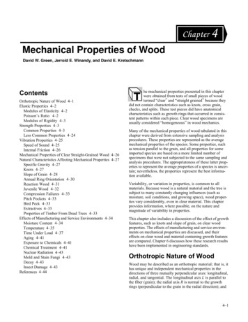
NailsNails are the most common mechanical fastenings used inwood construction. There are many types, sizes, and forms ofnails (Fig. 7–1). The load equations presented in this chapterapply for bright, smooth, common steel wire nails driveninto wood when there is no visible splitting. For nails otherthan common wire nails, the loads can be adjusted by factorsgiven later in the chapter.Nails in use resist withdrawal loads, lateral loads, or a combination of the two. Both withdrawal and lateral resistanceare affected by the wood, the nail, and the condition of use.In general, however, any variation in these factors has a morepronounced effect on withdrawal resistance than on lateralresistance. The serviceability of joints with nails laterallyloaded does not depend greatly on withdrawal resistanceunless large joint distortion is tolerable.The diameters of various penny or gauge sizes of brightcommon nails are given in Table 7–1. The penny size designation should be used cautiously. International nail producers sometimes do not adhere to the dimensions ofTable 7–1. Thus penny sizes, although still widely used, areobsolete. Specifying nail sizes by length and diameter dimensions is recommended. Bright box nails are generally ofthe same length but slightly smaller diameter (Table 7–2),while cement-coated nails such as coolers, sinkers, andcoated box nails are slightly shorter (3.2 mm (1/8 in.)) andof smaller diameter than common nails of the same pennysize. Helically and annularly threaded nails generally havesmaller diameters than common nails for the same penny size(Table 7–3).Withdrawal ResistanceThe resistance of a nail shank to direct withdrawal from apiece of wood depends on the density of the wood, thediameter of the nail, and the depth of penetration. The surfacecondition of the nail at the time of driving also influences theinitial withdrawal resistance.Table 7–1. Sizes of bright common wire .7152.4Diameter(mm 5)(0.244)(0.262)Table 7–2. Sizes of smooth box 212-1/211-1/210-1/2109Length(mm er(mm .148)Table 7–3. Sizes of helically and annularlythreaded nailsSizeFigure 7–1. Various types of nails: (left to right) brightsmooth wire nail, cement coated, zinc-coated, annularlythreaded, helically threaded, helically threaded andbarbed, and barbed.Length(mm ngth(mm /2)(5)(5-1/2)(6)(7)(8)(9)Diameter(mm (0.177)(0.177)(0.177)(0.177)(0.207)(0.207)(0.207)
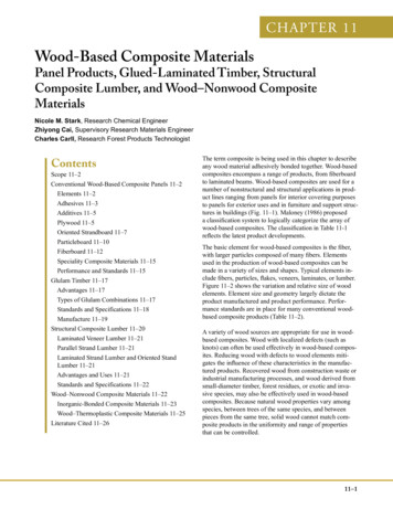
For bright common wire nails driven into the side grain ofseasoned wood or unseasoned wood that remains wet, theresults of many tests have shown that the maximum withdrawal load is given by the empirical equationp 54.12G 5 / 2DL(metric)(7–1a)p 7, 850G 5 / 2DL(inch–pound)(7–1b)where p is maximum load (N, lb), L depth (mm, in.) ofpenetration of the nail in the member holding the nail point,G specific gravity of the wood based on ovendry weight andvolume at 12% moisture content (see Ch. 4, Tables 4–2 to4–5), and D diameter of the nail (mm, in.). (The NDS andLRFD use ovendry weight and volume as a basis.)The loads expressed by Equation (7–1) represent averagedata. Certain wood species give test values that are somewhat greater or less than the equation values. A typical load–displacement curve for nail withdrawal (Fig. 7–2) showsthat maximum load occurs at relatively small values ofdisplacement.Although the equation for nail-withdrawal resistance indicates that the dense, heavy woods offer greater resistance tonail withdrawal than do the lower density ones, lighterspecies should not be disqualified for uses requiring highresistance to withdrawal. As a rule, the less dense species donot split as readily as the denser ones, thus offering an opportunity for increasing the diameter, length, and number of thenails to compensate for the wood’s lower resistance to nailwithdrawal.The withdrawal resistance of nail shanks is greatly affected bysuch factors as type of nail point, type of shank, time the nailremains in the wood, surface coatings, and moisture contentchanges in the wood.Displacement (in.)00.010.020.030.040.051607001205004006d smooth box nail2.49-mm (0.098-in.)diameter30031.8 mm (1-1/4 in.)penetration depth200Douglas-fir4012% moisture content1000800.54 specific gravity00.30.90.6Displacement (mm)1.2Figure 7–2. Typical load–displacement curve fordirect withdrawal of a nail.Withdrawal load (lb)Withdrawal load (N)600Effect of SeasoningWith practically all species, nails driven into green woodand pulled before any seasoning takes place offer about thesame withdrawal resistance as nails driven into seasonedwood and pulled soon after driving. However, if commonsmooth-shank nails are driven into green wood that is allowed to season, or into seasoned wood that is subjected tocycles of wetting and drying before the nails are pulled, theylose a major part of their initial withdrawal resistance. Thewithdrawal resistance for nails driven into wood that issubjected to changes in moisture content may be as low as25% of the values for nails tested soon after driving. On theother hand, if the wood fibers deteriorate or the nail corrodesunder some conditions of moisture variation and time, withdrawal resistance is erratic; resistance may be regained oreven increased over the immediate withdrawal resistance.However, such sustained performance should not be relied onin the design of a nailed joint.In seasoned wood that is not subjected to appreciable moisture content changes, the withdrawal resistance of nails mayalso diminish due to relaxation of the wood fibers with time.Under all these conditions of use, the withdrawal resistanceof nails differs among species and shows variation withinindividual species.Effect of Nail FormThe surface condition of nails is frequently modified duringthe manufacturing process to improve withdrawal resistance.Such modification is usually done by surface coating, surfaceroughening, or mechanical deformation of the shank. Otherfactors that affect the surface condition of the nail are the oilfilm remaining on the shank after manufacture or corrosionresulting from storage under adverse conditions; but thesefactors are so variable that their influence on withdrawalresistance cannot be adequately evaluated.Surface Modifications—A common surface treatment fornails is the so-called cement coating. Cement coatings,contrary to what the name implies, do not include cement asan ingredient; they generally are a composition of resinapplied to the nail to increase the resistance to withdrawalby increasing the friction between the nail and the wood. Ifproperly applied, they increase the resistance of nails towithdrawal immediately after the nails are driven into thesofter woods. However, in the denser woods (such as hardmaple, birch, or oak), cement-coated nails have practically noadvantage over plain nails, because most of the coating isremoved in driving. Some of the coating may also be removed in the side member before the nail penetrates themain member.Good-quality cement coatings are uniform, not sticky to thetouch, and cannot be rubbed off easily. Different techniques ofapplying the cement coating and variations in its ingredientsmay cause large differences in the relative resistance to withdrawal of different lots of cement-coated nails. Some nailsmay show only a slight initial advantage over plain nails. Inthe softer woods, the increase in withdrawal resistance of7–3
cement-coated nails is not permanent but drops off significantly after a month or so. Cement-coated nails are usedprimarily in construction of boxes, crates, and othercontainers usually built for rough handling and relativelyshort service.Nails with deformed shanks are sometimes hardened by heattreatments for use where driving conditions are difficult or toobtain improved performance, such as in pallet assembly.Hardened nails are brittle and care should be exercised toavoid injuries from fragments of nails broken during driving.Nails that have galvanized coatings, such as zinc, are intended primarily for uses where corrosion and staining resistance are important factors in permanence and appearance. Ifthe zinc coating is evenly applied, withdrawal resistance maybe increased, but extreme irregularities of the coating mayactually reduce it. The advantage that uniformly coatedgalvanized nails may have over nongalvanized nails in resistance to initial withdrawal is usually reduced by repeatedcycles of wetting and drying.Nail Point—A smooth, round shank nail with a long, sharppoint will usually have a greater withdrawal resistance,particularly in the softer woods, than the common wire nail(which usually has a diamond point). However, sharp pointsaccentuate splitting in certain species, which may reducewithdrawal resistance. A blunt or flat point without taperreduces splitting, but its destruction of the wood fibers whendriven reduces withdrawal resistance to less than that of thecommon wire nail. A nail tapered at the end and terminatingin a blunt point will cause less splitting. In heavier woods,such a tapered, blunt-pointed nail will provide about thesame withdrawal resistance, but in less dense woods, itsresistance to withdrawal is less than that of the common nail.Nails have also been made with plastic coatings. The usefulness and characteristics of these coatings are influenced by thequality and type of coating, the effectiveness of the bondbetween the coating and base fastener, and the effectiveness ofthe bond between the coating and wood fibers. Some plasticcoatings appear to resist corrosion or improve resistance towithdrawal, while others offer little improvement.Fasteners with properly applied nylon coating tend to retaintheir initial resistance to withdrawal compared with othercoatings, which exhibit a marked decrease in withdrawalresistance within the first month after driving.A chemically etched nail has somewhat greater withdrawalresistance than some coated nails, as the minutely pittedsurface is an integral part of the nail shank. Under impactloading, however, the withdrawal resistance of etched nails islittle different from that of plain or cement-coated nails undervarious moisture conditions.Sand-blasted nails perform in much the same manner aschemically etched nails.Shape Modifications—Nail shanks may be varied from asmooth, circular form to give an increase in surface areawithout an increase in nail weight. Special nails with barbed,helically or annularly threaded, and other irregular shanks(Fig. 7–1) are commercially available.The form and magnitude of the deformations along the shankinfluence the performance of the nails in various wood species. In wood remaining at a uniform moisture content, thewithdrawal resistance of these nails is generally somewhatgreater than that of common wire nails of the same diameter.For instance, annular-shank nails have about 40% greaterresistance to withdrawal than common nails. However, underconditions involving changes in moisture content of thewood, some special nail forms provide considerably greaterwithdrawal resistance than the common wire nail—about fourtimes greater for annularly and helically threaded nails of thesame diameter. This is especially true of nails driven intogreen wood that subsequently dries. In general, annularlythreaded nails sustain larger withdrawal loads, and helicallythreaded nails sustain greater impact withdrawal work valuesthan do the other nail forms.7–4Nail Head—Nail head classifications include flat, oval,countersunk, deep-countersunk, and brad. Nails with alltypes of heads, except the deep-countersunk, brad, and someof the thin flathead nails, are sufficiently strong to withstandthe force required to pull them from most woods in directwithdrawal. The deep-countersunk and brad nails are usuallydriven below the wood surface and are not intended to carrylarge withdrawal loads. In general, the thickness and diameter of the heads of the common wire nails increase as the sizeof the nail increases.The development of some pneumatically operated portablenailers has introduced nails with specially configured heads,such as T-nails and nails with a segment of the head cut off.Corrosion and StainingIn the presence of moisture, metals used for nails may corrode when in contact with wood treated with certain preservative or fire-retardant salts (Chs. 14 and 17). Use of certainmetals or metal alloys will reduce the amount of corrosion.Nails of copper, silicon bronze, and 304 and 316 stainlesssteel have performed well in wood treated with ammoniacalcopper arsenate and chromated copper arsenate. The choice ofmetals for use with fire-retardant-treated woods depends uponthe particular fire-retardant chemical.Staining caused by the reaction of certain wood extractives(Ch. 3) and steel in the presence of moisture is a problem ifappearance is important, such as with naturally finishedsiding. Use of stainless steel, aluminum, or hot-dippedgalvanized nails can alleviate staining.In general, the withdrawal resistance of copper and otheralloy nails is comparable with that of common steel wirenails when pulled soon after driving.DrivingThe resistance of nails to withdrawal is generally greatestwhen they are driven perpendicular to the grain of the wood.When the nail is driven parallel to the wood fibers (that is,
into the end of the piece) withdrawal resistance in the softerwoods drops to 75% or even 50% of the resistance obtainedwhen the nail is driven perpendicular to the grain. The difference between side- and end-grain withdrawal loads is less fordense woods than for softer woods. With most species, theratio between the end- and side-grain withdrawal loads ofnails pulled after a time interval, or after moisture contentchanges have occurred, is usually somewhat greater than thatof nails pulled immediately after driving.Toe nailing, a common method of joining wood framework,involves slant driving a nail or group of nails through theend or edge of an attached member and into a main member.Toe nailing requires greater skill in assembly than doesordinary end nailing but provides joints of greater strengthand stability. Tests show that the maximum strength oftoenailed joints under lateral and uplift loads is obtained by(a) using the largest nail that will not cause excessive splitting, (b) allowing an end distance (distance from the end ofthe attached member to the point of initial nail entry) ofapproximately one-third the length of the nail, (c) driving thenail at a slope of 30 with the attached member, and(d) burying the full shank of the nail but avoiding excessivemutilation of the wood from hammer blows.The results of withdrawal tests with multiple nail joints inwhich the piece attached is pulled directly away from themain member show that slant driving is usually superior tostraight driving when nails are driven into drywood andpulled immediately, and decidedly superior when nails aredriven into green or partially dry wood that is allowed toseason for a month or more. However, the loss in depth ofpenetration due to slant driving may, in some types ofjoints, offset the advantages of slant nailing. Cross slantdriving of groups of nails through the side grain is usuallysomewhat more effective than parallel slant driving throughthe end grain.Nails driven into lead holes with a diameter slightly smaller(approximately 90%) than the nail shank have somewhatgreater withdrawal resistance than nails driven without leadholes. Lead holes also prevent or reduce splitting of thewood, particularly for dense species.However, this improved strength of a clinched-nail joint doesnot justify the use of green lumber, because the joints mayloosen as the lumber seasons. Furthermore, laboratory testswere made with single nails, and the effects of drying, suchas warping, twisting, and splitting, may reduce the efficiencyof a joint that has more than one nail. Clinching of nails isgenerally confined to such construction as boxes and cratesand other container applications.Nails clinched across the grain have approximately 20%more resistance to withdrawal than nails clinched along thegrain.Fastening of PlywoodThe nailing characteristics of plywood are not greatly different from those of solid wood except for plywood’s greaterresistance to splitting when nails are driven near an edge.The nail withdrawal resistance of plywood is 15% to 30%less than that of solid wood of the same thickness. Thereason is that fiber distortion is less uniform in plywood thanin solid wood. For plywood less than 12.5 mm (1/2-in.)thick, the greater splitting resistance tends to offset the lowerwithdrawal resistance compared with solid wood. The withdrawal resistance per unit length of penetration decreases asthe number of plies per unit length increases. The directionof the grain of the face ply has little influence on the withdrawal resistance from the face near the end or edge of a pieceof plywood. The direction of the grain of the face ply mayinfluence the pull-through resistance of staples or nails withseverely modified heads, such as T-heads. Fastener designinformation for plywood is available from APA–TheEngineered Wood Association.Allowable LoadsThe preceding discussion dealt with maximum withdrawalloads obtained in short-time test conditions. For design,these loads must be reduced to account for variability, duration-of-load effects, and safety. A value of one-sixth the average maximum load has usually been accepted as the allowable load for long-time loading conditions. For normalduration of load, this value may be increased by 10%. Normal duration of load is defined as a load of 10-year duration.ClinchingThe withdrawal resistance of smooth-shank, clinched nails isconsiderably greater than that of unclinched nails. The pointof a clinched nail is bent over where the nail protrudesthrough the side member. The ratio between the loads forclinched and unclinched nails varies enormously, dependingupon the moisture content of the wood when the nail isdriven and withdrawn, the species of wood, the size of nail,and the direction of clinch with respect to the grain of thewood.Lateral ResistanceIn dry or green wood, a clinched nail provides 45% to 170%more withdrawal resistance than an unclinched nail whenwithdrawn soon after driving. In green wood that seasonsafter a nail is driven, a clinched nail gives 250% to 460%greater withdrawal resistance than an unclinched nail.where p is lateral load per nail, K a coefficient, and D diameter of the nail. Values of coefficient K are listed in Table 7–4for ranges of specific gravity of hardwoods and softwoods.The loads given by the equation apply only where the sidemember and the member holding the nail point are ofPre-1991Test loads at joint slips of 0.38 mm (0.015 in.)(approximate proportional limit load) for bright commonwire nails in lateral resistance driven into the side grain(perpendicular to the wood fibers) of seasoned wood areexpressed by the empirical equationp KD 3 / 2(7–2)7–5
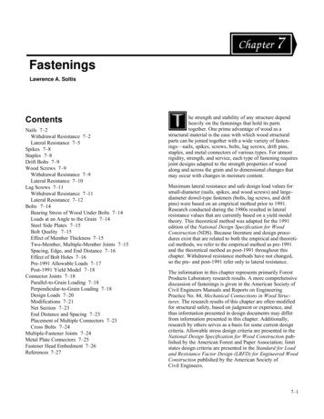
Lateral load coefficient K (metric (inch–pound))NailscScrewsLag screwsHardwoods0.33–0.47 50.04 (1,440) 23.17 (3,360) 26.34 (3,820)0.48–0.56 69.50 (2,000) 31.99 (4,640) 29.51 (4,280)0.57–0.74 94.52 (2,720) 44.13 (6,400) 34.13 (4,950)Softwoods0.29–0.42 50.04 (1,440) 23.17 (3,360) 23.30 (3,380)0.43–0.47 62.55 (1,800) 29.79 (4,320) 26.34 (3,820)0.48–0.52 76.45 (2,200) 36.40 (5,280) 29.51 (4,280)Wood with a moisture content of 15%.bSpecific gravity based on ovendry weight and volumeat 12% moisture content.cCoefficients based on load at joint slip of 0.38 mm(0.015 in.)aapproximately the same density. The thickness of the sidemember should be about one-half the depth of penetration ofthe nail in the member holding the point.The ultimate lateral nail loads for softwoods may approach3.5 times the loads expressed by the equation, and for hardwoods they may be 7 times as great. The joint slip atmaximum load, however, is more than 20 times 0.38 mm(0.015 in.). This is demonstrated by the typical load–slipcurve shown in Figure 7–3. To maintain a sufficient ratiobetween ultimate load and the load at 0.38 mm (0.015 in.),the nail should penetrate into the member holding the pointby not less than 10 times the nail diameter for dense woods(specific gravity greater than 0.61) and 14 times the diameterfor low density woods (specific gravity less than 0.42). Forspecies having densities between these two ranges, thepenetration may be found by straight line interpolation.Post-1991The yield model theory selects the worst case of yield modesbased on different possibilities of wood bearing and nailbending. It does not account for nail head effects. A description of the various combinations is given in Figure 7–4.Mode I is a wood bearing failure in either the main or sidemember; mode II is a rotation of the fastener in the jointwithout bending; modes III and IV are a combination ofwood bearing failure and one or more plastic hinge yieldformations in the fastener. Modes Im and II have not beenobserved in nail and spike connections. The yield modeltheory is applicable to all types of dowel fasteners (nails,screws, bolts, lag screws) , and thus the wood bearing capacity is described by a material property called the dowelbearing strength.7–6Load (kN)SpecificgravityrangebSlip in joint th0.450160Load (lb)Table 7–4. Coefficients for computing test loads forfasteners in seasoned wooda (pre-1991)8d common nail80360.05 xfastener Slip in joint (mm)diameter90Figure 7–3. Typical relation between lateralload and slip in the joint and 5% offset definition.The yield mode equations (Table 7–5) are entered with thedowel bearing strength and dimensions of the wood membersand the bending yield strength and diameter of the fastener.The dowel bearing strength of the wood is experimentallydetermined by compressing a dowel into a wood member.The strength basis is the load representing a 5% diameteroffset on the load–deformation curve (Fig. 7–3). Dowel2bearing strength Fe (Pa, lb/in ) is empirically related tospecific gravity G byFe 114.5G1.84(metric)(7–3a)Fe 16, 600G1.84(inch–pound)(7–3b)where specific gravity is based on ovendry weight andvolume.SpacingEnd distance, edge distance, and spacing of nails should besuch as to prevent unusual splitting. As a general rule, nailsshould be driven no closer to the edge of the side memberthan one-half its thickness and no closer to the end than thethickness of the piece. Smaller nails can be driven closer tothe edges or ends than larger ones because they are less likelyto split the wood.Grain Direction EffectsThe lateral load for side-grain nailing applies whether theload is in a direction parallel to the grain of the pieces joinedor at right angles to it. When nails are driven into the endgrain (parallel with the wood fibers), limited data on softwood species indicate that their maximum resistance tolateral displacement is about two-thirds that for nails driveninto the side grain. Although the average proportional limitloads appear to be about the same for end- and side-grainnailing, the individual results are more erratic for end-grainnailing, and the minimum loads approach only 75% ofcorresponding values for side-grain nailing.
(a)(b)(Not applicable)Mode ImMode IsMode IIMode ImMode IsMode IIMode IIIsMode IV(Not applicable)Mode IIImMode IIIsMode IVMode IIImFigure 7–4. Various combinations of wood-bearing and fastener-bending yields for (a) two-member connectionsand (b) three-member connections.Moisture Content EffectsNails driven into the side grain of unseasoned wood givemaximum lateral resistance loads approximately equal tothose obtained in seasoned wood, but the lateral resistanceloads at 0.38 mm (0.015 in.) joint slip are somewhat less.To prevent excessive deformation, lateral loads obtained forseasoned wood should be reduced by 25% for unseasonedwood that will remain wet or be loaded before seasoningtakes place.When nails are driven into green wood, their lateral proportional limit loads after the wood has seasoned are also lessthan when they are driven into seasoned wood and loaded.The erratic behavior of a nailed joint that has undergone oneor more moisture content changes makes it difficult to establish a lateral load for a nailed joint under these conditions.Structural joints should be inspected at intervals, and if it isapparent that the joint has loosened during drying, the jointshould be reinforced with additional nails.Deformed-Shank NailsDeformed-shank nails carry somewhat higher maximumlateral loads than do the same pennyweight common wirenails, but both perform similarly at small distortions in thejoint. It should be noted that the same pennyweight deformed-shank nail has a different diameter than that of thecommon wire nail. These nails often have higher bendingyield strength than common wire nails, resulting in higherlateral strength in modes III and IV.Lateral Load–Slip ModelsA considerable amount of work has been done to describe, bymathematical models, the lateral load–slip curve of nails.These models have become important because of their needas input parameters for advanced methods of structuralanalysis.One theoretical model, which considers the nail to be a beamsupported on an elastic foundation (the wood), describes theinitial slope of the curve: ( J J 2 )2 δ P 2( L1 L2 ) 1 (K 1 K 2 ) (7–4)where P is the lateral load and δ is the joint slip. The factorsL1, L2, J1, J2, K1, and K2 (Table 7–6) are combinations ofhyperbolic and trigonometric functions of the quantities λ1aand λ2b in which a and b are the depth of penetration of thenail in members 1 and 2, respectively. For smooth roundnails,λ 24k0(7–5)πED 3where k0 is elastic bearing constant, D nail diameter, and Emodulus of elasticity of the nail. For seasoned wood, theelastic bearing constant k0 (N/mm3, lb/in3) has been shown tobe related to average species specific gravity G if no lead holeis used byk 0 582G(metric)(7–6a)k 0 2, 144, 000G(inch–pound(7–6b)k 0 869G(metric)(7–7a)k 0 3, 200, 000G(inch–pound)(7–7b)If a prebo
7–2 Nails Nails are the most common mechanical fastenings used in wood construction. Th