Transcription
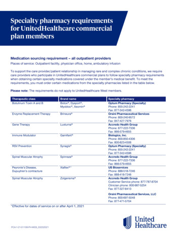
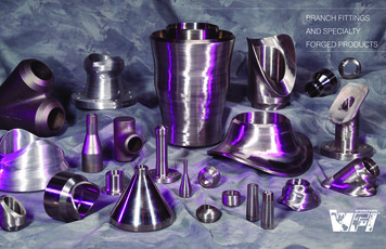
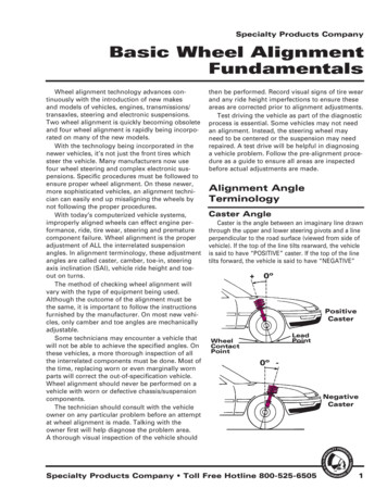
Specialty Products CompanyBasic Wheel AlignmentFundamentalsWheel alignment technology advances continuously with the introduction of new makesand models of vehicles, engines, transmissions/transaxles, steering and electronic suspensions.Two wheel alignment is quickly becoming obsoleteand four wheel alignment is rapidly being incorporated on many of the new models.With the technology being incorporated in thenewer vehicles, it’s not just the front tires whichsteer the vehicle. Many manufacturers now usefour wheel steering and complex electronic suspensions. Specific procedures must be followed toensure proper wheel alignment. On these newer,more sophisticated vehicles, an alignment technician can easily end up misaligning the wheels bynot following the proper procedures.With today’s computerized vehicle systems,improperly aligned wheels can effect engine performance, ride, tire wear, steering and prematurecomponent failure. Wheel alignment is the properadjustment of ALL the interrelated suspensionangles. In alignment terminology, these adjustmentangles are called caster, camber, toe-in, steeringaxis inclination (SAI), vehicle ride height and toeout on turns.The method of checking wheel alignment willvary with the type of equipment being used.Although the outcome of the alignment must bethe same, it is important to follow the instructionsfurnished by the manufacturer. On most new vehicles, only camber and toe angles are mechanicallyadjustable.Some technicians may encounter a vehicle thatwill not be able to achieve the specified angles. Onthese vehicles, a more thorough inspection of allthe interrelated components must be done. Most ofthe time, replacing worn or even marginally wornparts will correct the out-of-specification vehicle.Wheel alignment should never be performed on avehicle with worn or defective chassis/suspensioncomponents.The technician should consult with the vehicleowner on any particular problem before an attemptat wheel alignment is made. Talking with theowner first will help diagnose the problem area.A thorough visual inspection of the vehicle shouldthen be performed. Record visual signs of tire wearand any ride height imperfections to ensure theseareas are corrected prior to alignment adjustments.Test driving the vehicle as part of the diagnosticprocess is essential. Some vehicles may not needan alignment. Instead, the steering wheel mayneed to be centered or the suspension may needrepaired. A test drive will be helpful in diagnosinga vehicle problem. Follow the pre-alignment procedure as a guide to ensure all areas are inspectedbefore actual adjustments are made.Alignment AngleTerminologyCaster AngleCaster is the angle between an imaginary line drawnthrough the upper and lower steering pivots and a lineperpendicular to the road surface (viewed from side ofvehicle). If the top of the line tilts rearward, the vehicleis said to have “POSITIVE” caster. If the top of the linetilts forward, the vehicle is said to have “NEGATIVE” 0ºPositiveCasterLeadPointWheelContactPoint0º -Specialty Products Company Toll Free Hotline 800-525-6505NegativeCaster1
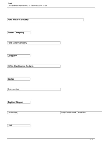
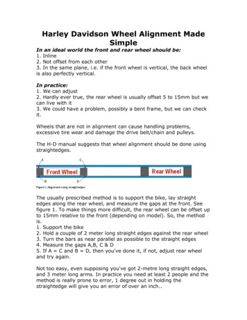
Basic Wheel Alignment Fundamentals - Continuedcaster.Positive caster can also be defined as when thespindle is tipped so that the pivot support centerlineintersects the road surface at a point in front of theinitial tire contact. Negative caster would then be thecenter line intersection to the road surface behind theinitial tire contact.Most vehicles produced today do not have adjustable caster angle. Many early model vehicles haveadjustable caster in which road crown is compensatedfor (along with camber). By setting the caster angle onthe driver’s side 1/2 degree less than the passenger sidefor positive caster specifications or 1/2 degree more fornegative caster specifications, the road crown shouldnot cause vehicle pull in either direction.Vehicles equipped with manual steering use verylittle positive or negative caster. This helps reduce thesteering effort at the steering wheel. The advantage ofcaster adjusted toward negative is greater maneuverability; however, direction stability on open road driving is reduced. The advantage of positive caster is thestrong directional stability and the ease of returning thesteering to a straight-ahead position.Caster will not cause tire wear unless extreme misadjustment or worn parts are involved. Always set caster (if adjustable) to specifications and within 1/2 degreefrom side to side. Keep road crown in mind and adjustas necessary if a pull is present after a proper alignment has been completed.Front Camber AngleThe camber angle will affect the wear on the inneror outer edge of the tire. Camber is the inclination ofthe centerline of the wheel from the vertical as viewedfrom the front of the vehicle. Camber angle is measuredin positive or negative degrees. Positive camber is theoutward tilt of the top of the tire. Negative camberis the inward tilt of the tire at the top. If a tire wasabsolutely vertical, the degree of camber would be zero.Unlike the caster angle, camber will change withvehicle load and ride height. With the weight of thedriver in the vehicle, front left camber will increaseand front right camber will decrease. As rough roadconditions are encountered, the downward thrust ofthe vehicle body will cause front camber to go negative. As the vehicle body movement returns upward,front camber will go positive. As camber oscillates, toeadjustment will also change with each movement of thecontrol arm.A tire with positive camber can influence the vehiclewith a directional pull. The vehicle will go towards the2side that has the tire with the most positive camber. It isthe normal tendency of the tire to roll around the center-0º Positive Camber0ºNegative Camberof a circle when the top of the tire is inclined towardsthe center of that circle.Positive camber tends to place the tire-to-road contact area nearer the point of load. This assists in easiersteering and forces the thicker inner portion of thespindle to carry most of the load. Modern suspensiondesign has reduced the need for considerable positivecamber. Many manufacturers specify a slight amount ofnegative camber.Some manufacturers recommend an additional 1/4to 1/2 degree positive camber on the left wheel to compensate for road crown. The car will then pull towardthe side with greater positive camber. This will offsetthe pull effect of the road crown. Always set camberwithin specifications.Rear Camber Angle Front Wheel DriveRear wheel camber angle is being relied on forimproved steering and general handling performance.In the past FWD vehicles and independent rear suspension vehicles were most likely to have adjustablerear camber. On vehicles currently being produced, rearcamber adjustment capabilities are being found on alltypes of models.Note: Always use full-floating tables under wheelswhenever alignment is being done.When alignment problems are reported on vehicleswith fixed rear axles and no rear wheel camber adjustment capabilities, a thorough inspection of the rearsuspension should be made. Damaged or worn components can cause alignment and/or steering problems.Replacing or repairing the defective components shouldbring the rear wheel assemblies into specification.Specialty Products Company Toll Free Hotline 800-525-6505
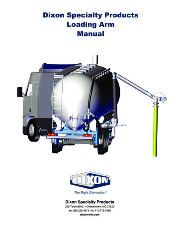
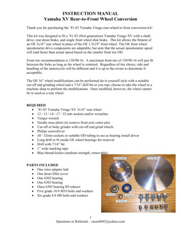
Basic Wheel Alignment Fundamentals - ContinuedOn vehicles where rear wheel camber is adjustable,all previous precautions apply. If camber adjustmentrequirements are excessive, a thorough inspection mustbe performed. Replacing any defective componentscould bring the camber into specification and adjustment may become unnecessary. As with the front suspension, DO NOT perform alignment on vehicles withdamaged or worn components.Whether the rear suspension is adjustable or not, ifall components are in good condition and the properspecifications cannot be obtained, aftermarket correction kits may be needed. Many of these kits are available from Specialty Products Company.Rear Camber Angle Rear Wheel DriveOn RWD vehicles, where rear camber is usually notadjustable, camber will normally be fixed at zero. Eventhough this angle cannot be changed through adjustment, if rear suspension abnormalities exist, a thoroughinspection must be made.Not to be overlooked are the rear springs. Worn orweak rear springs will alter riding height and becauseof a reduction in tension, will bring the shock absorbersout of the optimum range of their dampening ability.The result will be excessive tire movement. This condition reduces operator control and contributes to abnormal tire wear. As in FWD vehicles, replacing worn ordefective components may bring rear wheels withinspecification.Toe-In and Toe-OutUnlike caster and camber, which are measured indegrees, toe is most frequently measured in fractionalinches, millimeters or decimal degrees. The systemof measurement selected will depend on the type ofequipment available. An incorrect toe setting is one ofthe main alignment factors that cause excessive tirewear. Front and rear toe are the same in definition, withthe adjustment capabilities and procedures being theonly actual difference.Toe is the difference between the leading edge (orfront) and trailing edge (or rear) of the tires. Toe-in isthe measurement in fractions of an inch, millimeters ordecimal of degrees that the tires are closer together inthe front than they are in the back. Toe-out is the samemeasurement, except the tires are further apart in thefront than in the rear.Some manufacturers measure the angular changefrom straight-ahead in degrees. Slight toe-in is preferred to toe-out on most vehicles because steering isaligned while the vehicle is stationary. When the vehicleToeInToeOutis moving, linkage components flex causing a change inalignment angles. This is classified as “Running Toe.”Running toe should be zero to maximize tire life andachieve the least rolling resistance.The usual tendency is for the tires to turn outwardwhile the vehicle is in motion, so most vehicles aredesigned with a static toe-in setting. The static toe-insetting will become zero as the linkage flexes when thevehicle is in motion. Always set toe to the manufacturer’s specifications.On vehicles with toe adjustment capability on therear, an alignment specialist can go beyond manufacturer’s specifications according to vehicle usage andcustomer requirements. With the proper equipment,the rear axle can be adjusted to perform aggressivelytoward demanding load and road conditions. Vehicleswith FWD and independent rear suspensions are morelikely to have adjustable rear toe. As with rear camber,properly adjusted rear toe will contribute to improvedsteering and handling characteristics. Full floatingtables must be used under the rear tires whenever toeis to be adjusted.If rear toe is out of specification a thorough inspection must be done, whether or not rear toe is adjustable. Components found to be defective must bereplaced. On vehicles that do not have rear toe adjustment capability and toe is not within specifications,replacing defective components may bring toe withinspecifications.If proper toe specifications cannot be obtained,alignment correction kits may have been developedsince the vehicle was produced. Contact SpecialtyProducts Company to see if any of these types of kitsare available for the vehicle.Toe-Out on TurnsWhen a vehicle enters a turn, the outer tire musttravel a greater distance than the inner tire. The tirecenter is tangent to the turn circle. If the tires were toSpecialty Products Company Toll Free Hotline 800-525-65053
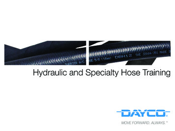
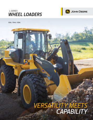
Basic Wheel Alignment Fundamentals - Continuedremain parallel in a turn, one tire would drag across theroad surface. This would create tire squeal, excessivetire wear and reduce handling performance.The outside front wheel must therefore be turnedat less of an angle than that of the inside front wheel.This will keep both wheels tangent to their respectiveturning circles and prevent tire squeal and/or damage.As the vehicle enters a turn, the tie rod ends will travelan equal distance, but due to the angle of the steeringarms the tires will progressively toe-out.Toe-Out onTurns(Also referred toas: Turning Angleor TurningRadius)Although this angle is never adjustable, it is easilychecked on the alignment rack by turning the tires 20degrees on full floating tables. First turn the front righttire 20 degrees and read the indicator on the left wheel.This is the angle of toe-out for the left tire. Repeatthe procedure for the remaining side. Compare readingwith specifications. Readings not within specificationsare an indication that the steering arms are bent andshould be replaced. Never bend or heat components torepair them.Steering Axis Inclination (SAI)Steering Axis Inclination (SAI) can be a difficultangle to understand. SAI is also referred to as the balljoint angle or kingpin inclination (on I-Beam suspension). The easiest way to understand SAI is to firstdefine steering axis. The steering axis is an imaginaryline intersecting the spindle support. In a conventionalsteering system, the spindle supports are the upper andlower ball joints or the kingpins. With MacPherson strutsystems, steering axis is the angle beginning at the balljoint and extended through the strut assembly.Viewed from the front of the vehicle, SAI is theangle between the steering axis and a true verticalline established through the tire. The SAI is a stabilityangle and is measured in degrees. If these imaginarylines were extended to the road surface, the area cov-4ered between them wouldbe identified as the pointof load or scrub radius.S.A.I.The vehicle body willbeclosest to the road surI.A.face when the wheels arepointed straight-ahead asa result of SAI. A spindlewith SAI will have theouter end of that spindleat the highest point whenthe wheels are pointedstraight-ahead. Therefore,as the weight of thevehicle pushes downward,the spindle will alwaysattempt to move upwardto return the wheels to astraight-ahead position.After a turn, the SAIhelps to return the tiresto straight-ahead position.SAI also aids in vehicle directional stability by resistingroad irregularities that attempt to turn the wheels awayfrom the straight-ahead position. SAI produces manyof the same benefits that improve steering stability aspositive caster. Correct engineering of SAI can reducethe need for high positive camber.The effect of SAI on directional stability is usuallygreater then that of caster. Some vehicles with powersteering require a greater amount of steering wheelreturning force than those with manual steering. SAIis often used with positive caster on power steeringequipped vehicles to assist in steering wheel returnability.CamberScrub RadiusScrub radius is the term used to describe the distance between the projected steering axis and the treadcenterline at the road surface. Scrub radius is positivewhen the centerline of the tire lies outside the projectedsteering axis. It is negative when the centerline of thetire is inside the projected steering axis. The scrubradius is a distance measurement and it is thereforemeasured in inches or millimeters.The size of the scrub radius depends on the steeringaxis inclination, wheel offset and the distance the spindle centerline is above the road surface. By carefullyconsidering the correct SAI and the proper wheel offsetfor the designed spindle height, the required amount ofscrub radius is designed into the suspension.Although the spindle height has an effect on thescrub radius, little can be done to change this heightSpecialty Products Company Toll Free Hotline 800-525-6505
Basic Wheel Alignment Fundamentals - Continuedbecause tire height is limited by the clearance spaceunder the fender and body. Since all handling sensations pass between the tire and the road, the scrubradius provides the necessary feedback to give thedriver road feel.SetbackSetback or front end squareness is a condition inwhich one wheel is rearward of the other. If setbackis present the turning radius will not be correct whenthe vehicle turns. With this condition, the tires willwear very much in the same manner as if they wereunder inflated. Generally,setback is the result ofcollision damage. It ispreferable to have thefront tires square witheach other before alignment is done.Considering the manydifferent types of alignment equipment available, it is not possibleto cover each checkingprocedure. Use the alignment machine manufacturer’s instructions forchecking setback. Themost accurate way ofchecking is with four wheel alignment equipment.Depending on the severity of setback and the typeof alignment equipment being used, false readings canmislead a technician into thinking that an incorrectadjustment is within specification. These false readingsare experienced more frequently with two wheel alignment methods.Thrust AngleThrust angle is the line that divides the total angle ofthe rear wheels. The rear tires are not just following thefront tires, they are actually establishing direction of thevehicle. In doing so, a direction of thrust is developed.The thrust angle created by the rear wheels is usedas a reference for aligning the front wheels. Ideally,the thrust angle should be identical to the geometriccenterline of the vehicle.If thrust angle and geometric centerline are identical,the position of the tires would then form an absoluterectangle and the front tires could be aligned to the reartires, resulting in a perfectly centered steering wheel.Because of unitized construction, factory tolerancesand a varying degree of damage and/or wear, it isincreasingly unlikely that the axles will be parallel.When the rear axle projects a different angle than thefront axle, the driver will need to turn the steeringwheel to compensate in order to drive in a straight line.On situations where the thrust line and terline are not identical, a thorough inspection ofthe rear axle and suspension system must be done.Replacing defective components should aid in positioning thrust angle close to the geometric centerline.If the thrust angle is not identical to the geometriccenterline and there are no defective components, alignthe vehicle using the thrust angle instead of the geometric centerline. Aligning the front wheels to the thrustangle is preferred to aligning to the geometric centerline. The ability to do this is a significant advantage offour wheel alignment. The result should be a straightsteering wheel as the vehicle moves straight-ahead.Pre-Alignment ProceduresTire InspectionInspection of the tires can help in diagnosing somewheel alignment failures. The tire wear pattern willrecord improper alignment of camber or toe settings.Some wear patterns associated with improper alignment include single shoulder wear, cupping and featheredging. Some tire defects are not visually noticeable,but can affect wheel alignment. Check each wheel andtire for radial runout.Proper tire pressure is essential for properly aligningwheels. The correct pressure not only allows tires toperform at the standard for which they were designed,but is directly related to ride height. Remember thatcold tires will register a slightly lower pressure thantires that are warm for usage. Tires with low pressureSpecialty Products Company Toll Free Hotline 800-525-65055
Basic Wheel Alignment Fundamentals - Continuedwill wear both outer edges. Over inflation will wear thecenter of the tires.Tire size and make, if different can cause a vehiclewith accurate wheel alignment to have a directionalpull or non-centered steering wheel. If tire sizes match,but brands and tread design differ, measure each tireindividually. There is no manufacturer standard thatdictates what the dimension of a given tire size willactually be.Ride HeightAlignment geometry angles are established from theride height. An improper ride height will affect thealignment geometry angles. Ride height can be affectedby several different components. Improper tire size,pressure, or springs (sagged, weakened or broken), willreduce ride height and cause the geometry angles to beout of specification.If enough adjustment is remaining, the alignmentangles may be brought within specifications. This may,however, produce a substandard wheel alignment. Withthe increase of weight and vehicle motion the originalproblem will reappear with the possibility of additionalrepair requirements.Several different areas should be measured toensure vehicle ride height is at the factory specifications.Front Component InspectionIf weak or defective components are undetected andan alignment is done, premature wear and damage canoccur on other components. It is therefore essentialthat all components are thoroughly inspected. Adjust orreplace weak or defective components before checkingor making the alignment adjustments.Check control arms, stabilizer bar, strut rods andsteering linkage for damage, wear indication or bentcomponents. Look closely at bushings for signs of deterioration and improper positioning. Replace bushingsas necessary. Check, measure and service ball joints,referring to a ball joint inspection service manual asnecessary.Check tie rod ends for excessive up and down movement by squeezing the ends. Very little or no up anddown movement should be present. Check idler armand pitman arm for excessive play. Idler arm or pitmanarm movement, other that normal turning movementshould not be present. Replace components as necessary.Check wheel bearing play and service bearings as6necessary. Check shock absorbers for leakage andweakness. Inadequate shock absorbers will not onlyaffect ridability, handling and alignment, they will alsocause premature failure of suspension components.Rear Component InspectionIt is important to understand that unrepaired, weakand/or damaged components will add to the total collective tolerance of the steering/suspension system.This total tolerance will continuously allow alignmentangles to change during vehicle operation. To maintaina quality alignment, replace all components which arenot within specifications.Although some vehicles do not have adjustable rearsuspensions, the rear wheel position is vital to a properly aligned vehicle. With four wheel alignment equipment available, the rear wheels can be checked inproportion to the front wheels or vice versa. Manyrear wheel specifications are available even on vehicleswithout adjustable rear wheels.If a visual inspection shows no abnormal or defective components, checking rear wheel alignment specifications (if available) will assure there are no hiddenrear wheel components that are damaged or worn. Ifthe rear wheels are not within alignment specifications,the technician should begin a thorough check of therear suspension system.Although the rear wheels are not adjustable, components can be replaced. Replacing components, whichare bent or worn, should bring the rear wheels intospecifications. With the rear wheels within specifications, a more accurate front wheel alignment can beaccomplished. If rear suspension is incorrect prior toalignment, the steering wheel and front wheel geometry will be off center.Tire Wear DiagnosisBecause of the rigorous routine the front suspensionmust endure, the front tires have to work much harderthan the rear tires. Even when the suspension is ingood condition and the alignment is set correctly, thefront tires will wear faster than the rear tires in mostcases. This is the reason for tire rotation at regularintervals.When an abnormal condition develops in the suspension system, it will usually affect the tires and ride.When this happens, one or even both tires can beaffected and begin a wear pattern characteristic of theproblem.Specialty Products Company Toll Free Hotline 800-525-6505
Basic Wheel Alignment Fundamentals - ContinuedIf a vehicle has a suspension malfunction, the wearpattern of the tire should readily show what the problem is. Typically where multiple malfunctions haveexisted for many miles, attempting to get an accuratediagnosis can be difficult or impossible.Tire SmoothOn One SideWhen a tire iswearing smooth on oneside, it can safely beassumed that the wornarea is where road contact is being made. Inthis case, not only is thetire wear being significantly accelerated, butcontrol of the vehicleand handling performance are reduced.The major cause of this tire wear pattern is cambermisadjustment. Incorrect camber adjustment can resultfrom worn chassis parts, (springs, steering linkage,bushings, ball joints, etc.) or previous misalignment.Excessive positive camber will wear the outside edgeof the tire and excessive negative camber will wear theinside edge of the tire.Sometimes, incorrect toe adjustment will causeshoulder wear on one side (outside wear for toe-in andinside wear for toe-out). To correct the condition, alignment and tire rotation or replacement is necessary.FeatherEdgingFeather edging willnormally occur if thetoe adjustment is incorrect. Misadjustment oftoe can develop fromdefective chassis parts,incorrect turning radiusor misalignment.Defective chassis partsare not the direct causeof feather edging butwill allow toe to go out of adjustment resulting in awear pattern. Any change in the suspension height of avehicle will change toe measurement.Feather edging is identified by sliding the handacross the tire tread surface. Depending to whichextreme the toe is misadjusted (in or out), sharp edgeswill be felt in one direction and smoothness will be feltin the opposite direction. Feather edging can result in adirection pull and eventually ruin the tires.To correct the condition, alignment and tire rotationor replacement is necessary.Cupping AppearanceTires will begin to develop a “cupping” appearancewhen the vehicle suspension loses its abilityto absorb “jounce travel.” “Jounce travel” isthe upward movementof the tire in relation tothe vehicle’s downwardmovement. This condition most commonlyoccurs with weak shockabsorbers or incorrectshock application.Other factors thatshould be considered when tires “cup” are the springs,tire balance and wheel alignment (in this order). As thesprings sag, the shock absorber shaft will be loweredout of its effective range. When a vehicle has ineffectiveshocks and soft sagging springs, the vehicle becomessusceptible to excessive bouncing.The downward motion of the bounce will have a“digging” effect on the tire that produces the low spotof the cup. As this condition progresses, it will becomeself-perpetuating to the point that part replacementand/or tire rotation will not reverse the damage. Whenencountered, defective parts must be replaced and thetires rotated to the rear or replaced.When a tire begins to develop bald spots, the mostcommon cause is an unbalanced or defective tire.Occasionally, failure to rotate tires at regular intervalscan contribute to bald spots. In either case, the suspension system should be inspected. If defective components are found in the suspension system, consideration should be given as to whether or not the defectivecomponents could have caused the bald spots.If the wear pattern is not severe, balance and rotation of tires is recommended. In severe cases the tireshould be replaced. Always check the alignment andadjust as necessary.This condition usually develops through abuse andpoor maintenance. When tires are repeatedly under orover inflated the continuous stress can result in cracksrelated to fatigue at the tread.Other possibilities are excessive exposure to hightemperature roads, high speed driving, or carryingloads that exceed the rated load capacity. In severeSpecialty Products Company Toll Free Hotline 800-525-65057
Basic Wheel Alignment Fundamentals - Continuedcases, strong consideration should be given as towhether the tire should be replaced with a tire bettersuited to the vehicle’s operating requirements. In lesssevere cases, the best tires should be rotated to thefront axle. Always check the alignment and adjust asnecessary.Shoulder Wear (Both Sides)When a tire is under inflated, the sidewall and contact surface will be forced to fluctuate excessively.Initially, the contact surface will buckle and the tire willtravel on the edges. The immediate result is shoulderwear because the outer treads are receiving all roadcontact.The amount of under inflation will determine theamount and severity of the tire wear. Considerationshould also be given as to whether the tire should bedismounted for inner sidewall damage inspection. Thiscan result from excessive heat buildup due to the addedload displacement stress on the sidewalls. Check tiresfor slow leakage and repair as necessary.Center WearIf a tire shows signs of accelerated wear in the centerof the tire tread, it has most likely been over inflated.Excessive pressure causes the tire to bulge in the centerand will usually provide a noticeably stiff or hard ride.The added rigidity causes stress to the chassis and tirebelts.This symptom is easily identified because it isuncharacteristic of other abnormal wear conditions withone possible exception. If tires are at specified pressureand questioning of vehicle operator provides no clues,check wheel rim width in relation to the size of the tires.If the tires are too wide for the rim, center wear canbe a result.If the tire wear is severe, tire and/or rim replacementis recommended. In cases of minimal wear, a slightreduction of tire pressure may solve the problem.Alignment Troubleshooting8ConditionPossible CauseCamber Not AdjustableControl arm bent.Frame bent.Hub and bearings not properly seated.Sagging springs.Front End ShimmyExcessive wheel/rim runout.Power steering reaction bracket loose.Steering gear box (rack) mount loose.Steering gear adjustment loose.Tires out of balance.Tires out of round.Wheel bearings worn or loose.Worn steering/suspension components.Hard SteeringBall joint tight or seized.Bent steering knuckle or support
formance, ride, tire wear, steering and premature component failure. Wheel alignment is the proper adjustment of ALL the interrelated suspension angles. In alignment terminology, these adjustment angles are called caster, camber, toe-in, steering axis inclination (SAI), v