Transcription
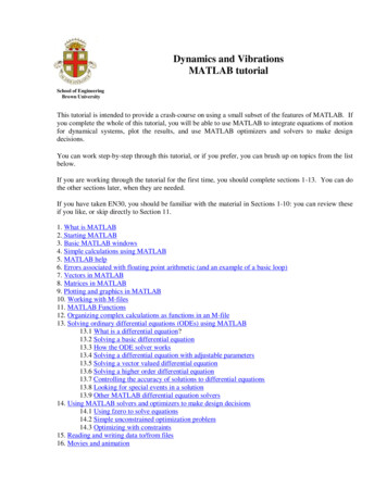
LOPA TutorialIntroductionA Layers of Protection Analysis (LOPA) is a semi-quantitative study that helps identify safeguardsand determine if there are sufficient safeguards to prevent against a given risk. A LOPA isconducted to ensure that process risks are successfully mitigated to an acceptable level. Figure 1below is a visual to represent the layers of protection for a given process. The layers in the diagramare ranked from 1-9 as most-least desirable safeguards.Figure 1. Layers of Protection Example Visual [5]A LOPA is developed on the basis of a risk identification analysis, such as a Hazard andOperability Study (HAZOP). A HAZOP is usually carried out first and is then followed by a LOPAstudy. A HAZOP is a structured analysis of process design to identify process safety incidents thata facility is vulnerable to. A detailed HAZOP overview can be found in the HAZOP tutorial here.Major hazardous scenarios, which have the potential to cause serious harm to people, environment,or business, that are discovered in a HAZOP are subjected to a LOPA. A HAZOP identifiespotential hazards, while a LOPA quantifies the probability of the hazard, analyzes the system atrisk, and identifies the mitigation measures that guard against the hazard. LOPA studies can beconducted with few resources, focus attention on major issues, eliminate unnecessary safeguards,establish valid safeguards to improve processes, and provides a basis for managing layers ofprotection. These mitigation safety measures, or “layers of protection” must meet the Center forChemical Process Safety (CCPS) criteria of being Independent Protection Layers (IPL).
Definitions and Relevant InformationIndependent- Not requiring or relying on anything elseRequirements for Independent Protection Layers (IPL)1) An IPL is effective in preventing the consequence2) An IPL functions independently of the initiating event of the scenario and functionsindependently of all other layers that are used for that same scenario3) An IPL is auditable (must be capable of validation including review, testing, anddocumentation)There are many different possible independent protection layers that can be used in aprocess. Here is a list of examples of IPLs: Inherently Safer Design Elimination or significant reduction of certain hazards Examples include reducing the quantity of material involved, changingprocess condition, eliminating flanges, using less hazardous material, etc. Basic Process Control System (BPCS) First layer of protection during normal operation which is designed tomaintain process within a safe operating region. It avoids operator intervention as process controls are done using controlsystem. Example could be a level transmitter controlling tank level by manipulatingbottom control valve. Alarm & Operator Intervention Second level of protection which alerts operator of deviation in operatingparameters. Examples are high level alarm, high pressure alarm Safety Instrumented System (SIS) Detects out of limit conditions and acts to bring the process back to a safestate Examples are Independent high-level switch, excess flow valves, automaticemergency shutdown etc. Physical Detection Devices Provide a high degree of protection against overpressure Examples are relief valves, rupture disc Passive Devices Reduces the risk by preventing undesired consequences such as widespreadleakage, widespread fire, etc. Dike, Blast walls, flame arrestors
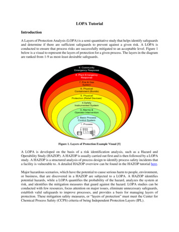
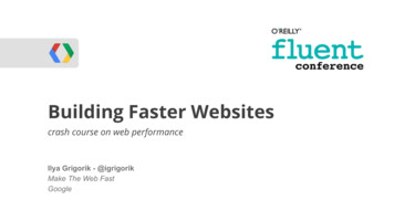
There are also many actions that are not considered independent layers of protection. Someexamples of are NOT considered an IPL are fire brigade, manual deluge systems, and communityresponses.Figure 2 below shows an example of an Independent IPL. It can be seen that each level transmitterhas its own control logic and valve. If one of the control logic fails, then only one level transmitterfails to function, and the other is unaffected. Therefore, the level transmitters are independent.Figure 3 below shows an example of a non-Independent IPL. It can be seen that the two leveltransmitters share the same control logic. If the control logic fails, then both the level transmittersfail to function Therefore, the level transmitters are not independent.Figure 2. Example of an Independent IPLFigure 3. Example of a Non-Independent IPLCategories of ConsequencesPotential consequences are ranked by their risk into categories 1-5. Category 1 includes the leastsevere consequences and category 5 includes the most severe. Consequences can put health, safety,and company finances at risk. Some consequences put safety and company finances at differentlevels of risk. For example, an incident could create a “category 5” consequence for safety butonly a “category 3” consequence for finances. When determining the severity, consider the safetyand business impacts independently and choose the highest severity.See Tables 1 and 2 for more information on the different categories of consequence.
Table 1. Categories Based on Safety ImpactSeveritySafety ImpactCategory 1SlightFirst Aid TreatmentCaseCategory 2MinorMinor Injury: DayAway from WorkCategory 3SevereSerious Injury:Hospital StayCategory 4MajorSingle FatalityCategory 5CatastrophicMultiple FatalitiesTable 2. Categories Based on Business ImpactSeverityBusiness ImpactCategory 1Slight 0 - 100,000Category 2Minor 100,000 1 millionCategory 3Severe 1 - 10 millionCategory 4Major 10 - 100 millionCategory 5Catastrophic 100 millionLOPA studies generally address approximately 5% of the significant risks issues. Most companiesdevelop limits for LOPA studies, often focusing on major consequences of category 4 or 5 andaccidents with fatalities. Most accidents occur during startup and shut down, consequently, aLOPA is often focused on consequences from incidents involving startup and shut down ofequipment.Frequency of Initiating Event (FOIE)FOIE describes how often the initiating event, which is the failure that causes the givenconsequence, will occur. Initiating events can passive or active. Initiating events could be a naturalphenomenon, control system failure, human error, etc. Probabilities of a given initiating eventoccurring can be found in Appendix A. When human error is deemed the initiating event, pleasefollow the steps here:1. Find the opportunity rate (the number of times that an activity is carried out by human annually)2. Find human error probability (HEP). This represents probability of human mistakes in a givenopportunity. The value is normally taken as 10-2/OpportunityFOIE Opportunities/year x HEPProbability of Failure of IPL on demand (PFD)PFD describes how often the protection layer will fail. Probabilities that a given layer will fail canbe found in Appendix B.Mitigated consequence frequency (MCF)MCF describes how often an initiating event will occur and the IPL will fail. MCF is the frequencythat a given consequence (see examples in Table 1) will occur. MCF is calculated by the givenformula:𝑀𝐶𝐹 𝑃𝐹𝐷 𝑥 𝐹𝑂𝐼𝐸
LOPA ProcessThe following method can be used for conducting a LOPA for any given system that possessespotential hazards:1) Identify a single consequence to a potential process safety hazard2) Identify an accident scenario and cause associated with the consequence3) Identify the initiating event for the scenario and estimate the frequency of initiating event(FOIE).4) Identify the independent protection layers that are available for this particular consequenceand estimate the probability of failure on demand (PFD) for each protection layer5) Combine the frequency of initiating event (FOIE) with the probability of failure (PFD) ofthe independent protection layer (IPL) to determine the mitigated consequence frequency(MCF) for the given initiating event6) Plot the consequence frequency vs consequence severity to estimate the level of risk asseen below in Table 2. Each point will fit somewhere on this risk matrix.𝑅𝑖𝑠𝑘 𝑀𝐶𝐹 𝑥 𝑆𝑒𝑣𝑒𝑟𝑖𝑡𝑦Table 2. Risk MatrixCategory 5Category 4Category 3Category 2Category 1Rare:1 consequenceevery 10,000years(MCF 0.0001/year)Unlikely:1 consequenceevery 1000years(MCF 0.001/year 0.01/year)Possible:1 consequenceevery100 years(MCF 0.01/year 0.1/year)Probable:1 consequenceevery 10 years(MCF 0.1/year 1/year)HighlyProbably:1 consequenceevery 1 year(MCF 1/year)severe riskmajor riskmoderate riskminor risk7) Compare risk found in step 6 to an acceptable level of risk and evaluate if additional IPLsare necessary
While you are completing a LOPA, please consider the following:1.2.3.4.All the IPLs are maintained and working properlyNumber of injuries/fatalities/economic loss as per CSB reportAn initiating event cannot be taken as an IPLIf there are multiple IPLs in the system, then PFD of system will be product of eachindependent IPL PFD𝑃𝐹𝐷 𝑃𝐹𝐷1 𝑃𝐹𝐷2 𝑃𝐹𝐷35.If there are no IPLs present, the PFD value is 1.Example Using Explosion at Caribbean Petroleum Company (CAPECO)In the CAPECO explosion, the main gasoline storage tank was full, so an additional shipment ofgasoline had to be stored in four smaller tanks using a highly manual process. One of the tanks hada broken level transmitter so fill time was manually calculated, and unfortunately overestimated.The tank overfilled and created a gasoline vapor plume, which found a spark and rapidly exploded.Watch the video here: https://www.youtube.com/watch?v 41QMaJqxqIo and view the incidentreport here: https://www.csb.gov/file.aspx?DocumentId 5965Before completing a LOPA for this example, a HAZOP was completed to expose potential hazardsin CAPECO’s facilities. You can view the completed interactive HAZOP worksheet for thisscenario here.After determining the main hazards in the system, a LOPA can be conducted as follows:1) Identify a single consequence to a potential process safety hazardAt CAPECO, the potential process safety hazard was the inaccurate filling of gasolinestorage tanks. The consequence was overfilling of flammable gasoline which could lead tofire.2) Identify an accident scenario and cause associated with theThe storage tank could overflow due to operator error and lead to a fire.consequence3) Identify the initiating event for the scenario and estimate the frequency of initiating event(FOIE).The initiating event would be manual operation leading to an operator error. Let’s assumenumber of opportunities to be 100/year. According to Appendix A, the frequency ofoperator error is 1x10-2.FOIE 1x10-2 x 100 1/year4) Identify the protection layers that are available for this particular consequence and estimatethe probability of failure on demand (PFD) for each protection layerPFD values can be found in Appendix B. In this example, only a single layer of protectionwas available: a dike, which reduces the frequency of large consequences of a tank overfillor spill.PFD (Dike) 1x10⁻²
5) Combine the frequency of initiating event (FOIE) with the probability of failure (PFD) ofthe independent protection layer (IPL) to determine the mitigated consequence frequency(MCF) for the given initiating eventMCF FOIE x PFD (Dike)𝑀𝐶𝐹 (1) 𝑥 (1𝑥10 2 ) 1𝑥10 2 /𝑦𝑒𝑎𝑟6) Plot the consequence frequency vs consequence severity to estimate the level of risk asseen in Table 2. Each point will fit somewhere on this risk matrix.An MCF of 1.0x10⁻²/year would mean there is 1 event every 100 years, which falls underthe label of “Possible”.In the CAPECO incident, there were no fatalities, but there were minor injuries (CSBreport, page 31) corresponding to “Category 2” based on Table 1. The business impactwas estimated to be more than 500 million, which corresponds to “Category 5”. So, theseverity category will be taken as the higher of the two, which is “Category 5”.Using the risk matrix in Table 2 above, an “possible” event of “Category 5” falls into anorange box, which corresponds to a major risk.7) Compare risk found in step 6 to an acceptable level of risk and evaluate if additional IPLsare necessaryIn this case, a major risk would NOT be acceptable. The layer of protection provided byinstalling a dike would not be adequate to prevent a major disaster.Since the risk is too high, additional layers of protection are needed. By adding more layersof protection, the MCF can be decreased which can lead to a different location in the riskmatrix. In this case, additional layers of protection could decrease the risk of this event to“moderate”, which is more acceptable than “major”.To do this, iterate back through steps 1-6, but using additional layers and PFD values.Then evaluate again until the risk is at an acceptable level.
To carry out a LOPA study in the safety modules, a table format will be used. A LOPA table forthe CAPECO explosion is filled out for your reference based on the discussion above. Considerthat the facility can only accept a moderate risk.LOPA Study for CAPECO ExplosionCause:Operator error leading to miscalculated filltimeConsequence:Gasoline tank overfill leading to vapor cloudexplosionFOIE:10-2 x 100 1.0/yearDescription of IPL1, IPL2, .Physical Containment (Dike)PFD PFD1 x PFD2 x .10-2MCF FOIE x PFD1.0 x 10-2 /yearCategory of MCF:PossibleImpact:Business loss of more than 500 millionCategory:5Type of risk:MajorAcceptable / Unacceptable?UnacceptableInitiating EventIPL(s)MCFSeverityRiskIf risk calculated above is unacceptable, please continue below:Description of P-IPL1, P-IPL2, .:Independent High-level alarm, Tank OverfillProtection System (SIS)P-PFD P-PFD1 x P-PFD2 x .10-1 x 10⁻¹ 10-2MCF FOIE x PFD x P-PFD1.0 x 10-2 /year x10-2 1.0x10⁻⁴ / yearCategory of MCF:RareType of risk:ModerateAcceptable / Unacceptable?AcceptableProposed IPL(s)(P-IPL(s))MCFRiskIt is important to note that sometimes seemingly sufficient IPLs will not be able to prevent adisaster. LOPA studies assume that equipment is well-maintained, and operators are wellprepared to complete their jobs effectively. If equipment is faulty and multiple layers ofprotection fail at once, unexpected incidents can still occur. While multiple layers of protectioncan usually prevent disasters, it is important to remember that some risks can still go undetectedif process safety is not prioritized.
Appendix A: Frequency of Initiating Event (FOIE) Values [1],[8]Initiating EventFOIE Value (per Year)Pressure vessel residual failure10 6Piping leak (10% section)10 3Atmospheric tank failure10 3Third-party intervention (e.g. external impact byvehicle)10 2Safety valve opens unexpectedly10 2Cooling water failure10 1Pump seal failure10 1Corrosion of tanks or equipment10 2Basic process control system (BPCS) instrumentloop failure10 1External fire10 1Operator failure10 2 /𝑜𝑝𝑝𝑜𝑟𝑡𝑢𝑛𝑖𝑡𝑦
Appendix B: Probability of Failure on Demand (PFD) Values [1],[8]IPLComments and DefinitionsPFD ValueDikeReduces the frequency of large consequences of a tankoverfill, rupture, spill, etc.10 2Underground drainingsystemReduces the frequency of large consequences of a tankoverfill, rupture, spill, etc.10 2Open ventPrevents overpressure10 2Motors, Fans, BlowersCan be used to reduce concentration of dusts by exhaustingair out of a system (e.g. dust collection system)10 2FireproofingReduces rate of heat input and provides additional time fordepressurizing, firefighting, etc.10 2Blast wall or bunkerReduces the frequency of large consequences of anexplosion by confining blast and by protecting equipment,buildings, etc.10 3Single Check Valve/ Slide Reduces the frequency of reverse flow by allowing flow inValveonly one direction10 1Dual Check Valve/ Slide More efficient than single check valve in reducingValvefrequency of reverse flow10 2Inherently safer designIf properly implemented, can eliminate scenarios, orsignificantly reduce the consequences associated with ascenario10 2Flame or detonationarrestorsIf properly designed, installed, and maintained, caneliminate the potential for flashback through a pipingsystem or into a vessel or tank10 2Relief Valve/Rupture DiskPrevents system from exceeding specified overpressure.10 2AlarmsAlarms can be programmed to alert the operator to take anaction10 1Basic process controlsystem (BPCS)Can be credited as an IPL if not associated with theinitiating event being considered.10 1Safety Instrumented System(SIS)SIS does not depend upon any operator interaction andworks automatically to bring system to a safe state duringan undesired event10 1Manual EmergencyShutdown (ESD)Manual activation of button to shut down entire process0.4
References[1] “LOPA – Layer of Protection Analysis.” Process and HSE Engineering, 2 Feb. ction-analysis/.[2] Summers, Angela E. (July 2014). “Introduction to Layer of Protection Analysis” (July 2014).SIS-Tech.[3] “Risk Assessment .” Chemical Process Safety: Fundamentals With Applications, by DanielA. Crowl and Joseph F. Louvar, 3rd ed., Pearson, 2011, pp. 577–587.[4] Gate Inc. “Introduction to Layer of Protection Analysis (LOPA)”. Gate Keeper: A TechnicalNewsletter for the Oil & Gas Industry (July 2014).[5] Spencer, Gabi. “Multiple Layers of Protection & Mitigation.” ESC, 26 Jan. ion/.[6] Shuttleworth, Mike. “Qualitative and Quantitative Risk Analysis. What Is the Difference?”Project Risk Manager, 13 Oct. 2019, uantitative-risk-analysis/.[7] “Independent.” Merriam-Webster, Merriam-Webster, www.merriamwebster.com/dictionary/independent .[8] Crowl, Daniel A., and Joseph F. Louvar. Chemical Process Safety: Fundamentals withApplications. Pearson, 2019.Created in Collaboration with Lydia Peters
LOPA Tutorial Introduction A Layers of Protection Analysis (LOPA) is a semi-quantitative study that helps identify safegua


![Unreal Engine 4 Tutorial Blueprint Tutorial [1] Basic .](/img/5/ue4-blueprints-tutorial-2018.jpg)