Transcription
FoodLivingOutsidePlayTechnologyWorkshopLED Binary Clockby emihackr97 on September 8, 2011Table of ContentsLED Binary Clock . . . . . . . . . . . . . . . . . . . . . . . . . . . . . . . . . . . . . . . . . . . . . . . . . . . . . . . . . . . . . . . . . . . . . . . . . . . . . . . . . . . . . . . . . . . . . . . . . . . . . . . . . . . . .1Intro: LED Binary Clock . . . . . . . . . . . . . . . . . . . . . . . . . . . . . . . . . . . . . . . . . . . . . . . . . . . . . . . . . . . . . . . . . . . . . . . . . . . . . . . . . . . . . . . . . . . . . . . . . . . . . .2Step 1: What you'll need . . . . . . . . . . . . . . . . . . . . . . . . . . . . . . . . . . . . . . . . . . . . . . . . . . . . . . . . . . . . . . . . . . . . . . . . . . . . . . . . . . . . . . . . . . . . . . . . . . . . .3Step 2: Selecting your box . . . . . . . . . . . . . . . . . . . . . . . . . . . . . . . . . . . . . . . . . . . . . . . . . . . . . . . . . . . . . . . . . . . . . . . . . . . . . . . . . . . . . . . . . . . . . . . . . . . .4Step 3: Mark your box. . . . . . . . . . . . . . . . . . . . . . . . . . . . . . . . . . . . . . . . . . . . . . . . . . . . . . . . . . . . . . . . . . . . . . . . . . . . . . . . . . . . . . . . . . . . . . . . . . . . . . .4Step 4: Add your LEDs . . . . . . . . . . . . . . . . . . . . . . . . . . . . . . . . . . . . . . . . . . . . . . . . . . . . . . . . . . . . . . . . . . . . . . . . . . . . . . . . . . . . . . . . . . . . . . . . . . . . . .4Step 5: Wiring 1 . . . . . . . . . . . . . . . . . . . . . . . . . . . . . . . . . . . . . . . . . . . . . . . . . . . . . . . . . . . . . . . . . . . . . . . . . . . . . . . . . . . . . . . . . . . . . . . . . . . . . . . . . . .5Step 6: Wiring 2 . . . . . . . . . . . . . . . . . . . . . . . . . . . . . . . . . . . . . . . . . . . . . . . . . . . . . . . . . . . . . . . . . . . . . . . . . . . . . . . . . . . . . . . . . . . . . . . . . . . . . . . . . . .5Step 7: (If using an Arduino) . . . . . . . . . . . . . . . . . . . . . . . . . . . . . . . . . . . . . . . . . . . . . . . . . . . . . . . . . . . . . . . . . . . . . . . . . . . . . . . . . . . . . . . . . . . . . . . . . .6Step 8: (If not using an arduino) Assemble the PCB . . . . . . . . . . . . . . . . . . . . . . . . . . . . . . . . . . . . . . . . . . . . . . . . . . . . . . . . . . . . . . . . . . . . . . . . . . . . . . . . .6Step 9: Test your clock. . . . . . . . . . . . . . . . . . . . . . . . . . . . . . . . . . . . . . . . . . . . . . . . . . . . . . . . . . . . . . . . . . . . . . . . . . . . . . . . . . . . . . . . . . . . . . . . . . . . . . .7File Downloads . . . . . . . . . . . . . . . . . . . . . . . . . . . . . . . . . . . . . . . . . . . . . . . . . . . . . . . . . . . . . . . . . . . . . . . . . . . . . . . . . . . . . . . . . . . . . . . . . . . . . . . . . . .7Step 10: Glue your pcb/arduino in place . . . . . . . . . . . . . . . . . . . . . . . . . . . . . . . . . . . . . . . . . . . . . . . . . . . . . . . . . . . . . . . . . . . . . . . . . . . . . . . . . . . . . . . . . .7Step 11: Power supply. . . . . . . . . . . . . . . . . . . . . . . . . . . . . . . . . . . . . . . . . . . . . . . . . . . . . . . . . . . . . . . . . . . . . . . . . . . . . . . . . . . . . . . . . . . . . . . . . . . . . . .8Step 12: How to read it . . . . . . . . . . . . . . . . . . . . . . . . . . . . . . . . . . . . . . . . . . . . . . . . . . . . . . . . . . . . . . . . . . . . . . . . . . . . . . . . . . . . . . . . . . . . . . . . . . . . . .9Step 13: Finally, place it! . . . . . . . . . . . . . . . . . . . . . . . . . . . . . . . . . . . . . . . . . . . . . . . . . . . . . . . . . . . . . . . . . . . . . . . . . . . . . . . . . . . . . . . . . . . . . . . . . . . . . 10Step 14: Future additions! . . . . . . . . . . . . . . . . . . . . . . . . . . . . . . . . . . . . . . . . . . . . . . . . . . . . . . . . . . . . . . . . . . . . . . . . . . . . . . . . . . . . . . . . . . . . . . . . . . . . 11Related Instructables . . . . . . . . . . . . . . . . . . . . . . . . . . . . . . . . . . . . . . . . . . . . . . . . . . . . . . . . . . . . . . . . . . . . . . . . . . . . . . . . . . . . . . . . . . . . . . . . . . . . . . . . 11Comments . . . . . . . . . . . . . . . . . . . . . . . . . . . . . . . . . . . . . . . . . . . . . . . . . . . . . . . . . . . . . . . . . . . . . . . . . . . . . . . . . . . . . . . . . . . . . . . . . . . . . . . . . . . . . . . . -1/
Author:emihackr97 emihackr97I am a guy searching for fun projects and trying to share my own ones.not much more to say.Intro: LED Binary ClockA Binary Clock!the other day, I was looking at some binary clocks and I felt like Why not? I have everything and I don't have a clock in my room.so I decided to build one and here it is, also, it's in the Clocks contest and in the Epilog contest, so please vote for it.Thanks!Now we can proceed.It's a cool project, and it's easy to make, it's highly customizable in both size/shape and firmware/functions, it is Arduino based/compatible AND it looks good.Image Notes1. Working!2. ock-1/
Step 1: What you'll needfor this project you will need the following things;Materials/components;cardbord/wood box(you choose the size)DC WallWart 5V out at least 250 mAArduino or Atmega328/168/88/48(if not using an Arduino) 16Mhz crystal and caps (the more precise, better).13x 220 Ohms Resistors.13x LEDs (your preferred color)A lot of Wire.3x pushbuttons (PCB mount)(optional) 1x LDR (light dependant Resistor) OR 1x Pushbutton (enclosure mount)Tools;Soldering Iron and solder.utter/Xacto Knife.wire strippers.Computer (I guess you have one if you're reading this).(if not using an Arduino) USBtiny ISP.Image Notes1. Working!2. ock-1/
Step 2: Selecting your boxThe easiest and fastest enclosure is a simple cardboard box, but you can also use a nicer plastic or wood box.Select your box, remove the back part from it.if it's a cardboard box, you might want to disassemble it and reassemble it inside out, like I did, that way its easier to paint or, leave it like that and it looks great!Step 3: Mark your box.You need a 4x4 grid, but don't make holes just yet, as you won't fill it all the way.in a cardboard box, I four it's easier to just make some small holes for the LED legs and insert them from the outside, other ways the cardboard will look awful and yourLEDs won't be "snapped to grid".At first, I marked my box on the inside, but after i decided that those Grid lines looked good, so I did them swell on the outside.Step 4: Add your LEDsPlace your 13 LEDs in your 4x4 grid as shown in the image below.from the inside, Bend all the Leads and place a drop of hot melt glue on top of each (Bottom, actually) (see image k-1/
Step 5: Wiring 1connect together all the POSITIVE leads (the longer ones) from each LED.Step 6: Wiring 2Add one wire to each LED's NEGATIVE lead. instead of the positive lead, connect the NEGATIVE ones, contrary to the diagram below. Remember, all the POSITIVEones are connected together, contrary to what the diagram lock-1/
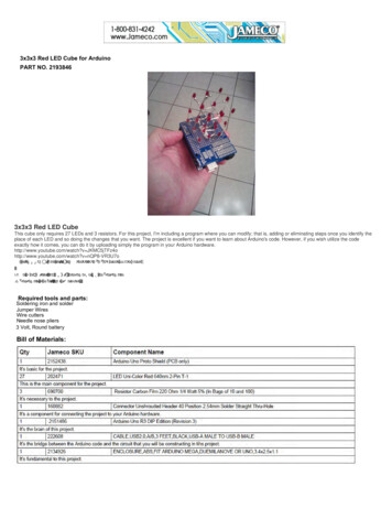
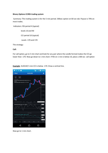
Step 7: (If using an Arduino)simply add one resistor to each wire going to each LEDs leads and connect them to the corresponding arduino pins, then connect a pushbutton to Arduino's digital pin 14(Analog 0), one to digital pin 18 (analog 4) and another to digital pin 19 (analog 5).the 14 pushbutton will change minutes, adding one for each time you press it.the 19 pushbutton will change hours, adding one for each time you press it.the 18 pushbutton (optional) will turn ON/OFF the LEDs, but keep counting the time, this is useful for sleeping time. :)the 18 LDR (optional, instead of the pushbutton) will turn the LEDs when ther's no light, e.g. at night. but keep them on when there is, like in the day or at night,when you turn on the lights.the proper LED to Arduino pin diagram is shown below, remember that it s the other way around, instead of all to Gnd, all to 5V, etc.Step 8: (If not using an arduino) Assemble the PCBI added the 2 time setting pushbuttons on the PCB, all the 13 resistors and the reset pushbutton.place your crystal, remember, the frequency is not critical, as long as you specify it on the arduino software, if you don't know how to do this, stick with 16Mhz, also, ifyou re using another frequency, remember that its recommended that it's a multiple of 8, e.g. 16mhz or 8 Mhz because Atmega chips are 8Bit micros.if you're a beginner, it's recommended to use an arduino, or at least an arduino ready, pre-bootloaded chip.the advantages of using an Atmega48 instead of an atmega328/arduino is mainly the price;an arduino costs about USD 30, an arduino pre boot loaded chip costs about USD 6, and an Atmega48 costs only about USD 1.5.NOTE: to be able to program Atmega chips without boot loader, using ISP from the arduino IDE you need to make some modifications to the IDE (I will not cover that inthis guide).if you use an Atmega48/88 without bootloader, you need to have some basic knowedlage on AVR fuses and how to work with the bare chip and program thru ISP.remember to add a 2 pin header for power and, mark which pin is Gnd and which one is 5V and add a 3 pin female header for connecting the (optional) pushbutton orLDR. one pin to Gnd, one to 5V and the other one to digital pin 18 (analog 4).Image Notes1. ISP programming header.2. Atmega48 chip, the brains of all this.3. Oscilator/crystal to accurately keep the time.4. reset5. minute setting pushbutton6. wires and resistors.7. Hot melt glue8. Hot melt glue9. Hot melt glue10. Hot melt glue11. Hot melt ck-1/
Step 9: Test your clock.Download the firmware below, there are 2 files, one for 24 hours and one for 12 hours.at this point it should be (almost) fully assembled, but already fully working, so flash your micro controller and try adding some minutes/hours and check if it changesevery minute. also check that the numbers it displays are correct, if not, check all your connections, check that the program you uploaded is the correct one and check forpower good (green LED on Adruinos).if you don't manage to solve your problem, post a coment describing it and i will try to help.the video shows me programming my clock and testing it.Image Notes1. Working!2. 16:52File DownloadsArduino LED binary clock.zip (14 KB)[NOTE: When saving, if you see .tmp as the file ext, rename it to 'Arduino LED binary clock.zip']Step 10: Glue your pcb/arduino in placeat this point, your clock should be tested and working, because, after this step, you won't be able to make any soldering or any other kind of Clock-1/
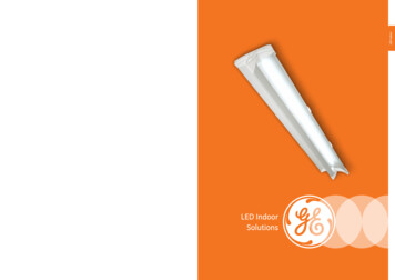
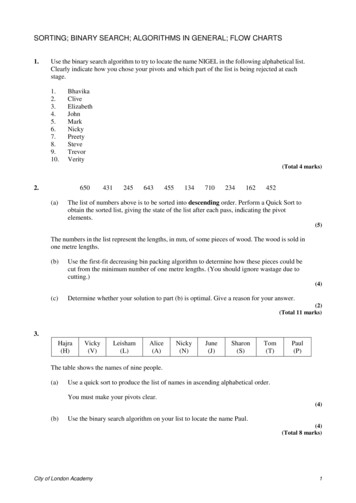
Image Notes1. ISP programming header.2. Atmega48 chip, the brains of all this.3. Oscilator/crystal to accurately keep the time.4. reset5. minute setting pushbutton6. wires and resistors.7. Hot melt glue8. Hot melt glue9. Hot melt glue10. Hot melt glue11. Hot melt glueStep 11: Power supply.I used an old WallWart that supplied 5 volts, i also made a power extension (for the 5v side) because the wallWart's wire wasn't long enough.you just need to cut the tip and exchange it for a 2 pin female header (in case of using your own pcb) or a male header (in case of using and arduino.Image Notes1. WallWart's modified ry-Clock-1/
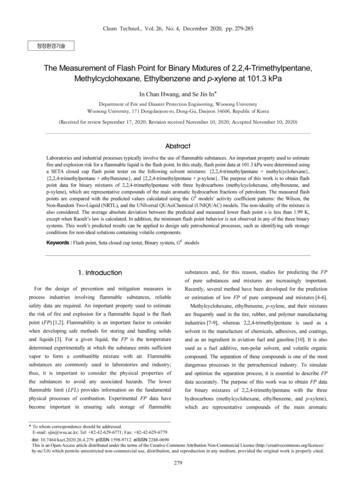
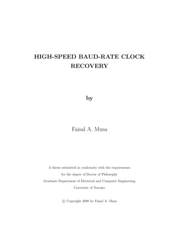
Image Notes1. power extension headers (i used black telephone cable.Step 12: How to read itthe secret lays in understanding how it works, it's really simple!It is a binary clock, it's a bit harder to read but that makes it cooler, you'll get used to it.the first 2 colums correspond to hours, toe 3rd and the 4th correspond to minutes. the 2nd and 4th colums are units and the 1st and 3rd ones are 10 of the correspondingunits (hours, Minutes).you need to add the lit up LEDs to get the time, see image 2 for an example (it's not as hard as it might seem, it's actually really easy)remember , if you make the 24 hour version, you will have a 12:00 hour in the afternoons, with the 12 hour one, you will have the normal time. (i think everybodyunderstands this part).Image Notes1. Minutes-Units2. minutes x103. hours- units4. hours k-1/
Step 13: Finally, place it!Finally, place it on the wall and enjoy!remember to set the correct time.also remember that, if the power goes out, the time will be lost.Image Notes1. the clock, on the ock-1/Image Notes1. my room2. LED cube 4x4x43. LED cube 3x3x3
Image Notes1. Working!2. 16:52Step 14: Future additions!- add an RTC (Real Time Clock) so it doesn't loos the time every time it is unplugged.- add a day of the week function.- add an alarm function that has day-dependant alarms and multiple ones.- something else I will think of.Related InstructablesHow to fix deadatmega andattiny avr chipsby manekinenThe TravelingGeocache! byRevolt LabBare BonesBreadboardArduino Labelsby dnhoshorHow to useArduino Mega2560 as Arduinoisp by tsillenArduino on allsorts of Atmelsby 02JanDalThe BestArduino bymsuzuki777Comments5 commentsAdd Commentdunnos says:Sep 15, 2011. 7:08 AM REPLYperhaps find a way to get cheap lasers? projectable binary clock!Tomasauk says:Sep 9, 2011. 3:17 AM REPLYThat is cool. I would make one. eventually, but I think I would find it tricky to read.emihackr97 says:Sep 9, 2011. 7:59 PM REPLYits a bit strange at the beginning, but you'll get used to it, i did! :)Tomasauk says:I might try to make this. Do you think there is any other way to supply power to the clock, the wire looks out of place.Or I could put it on a ock-1/Sep 10, 2011. 5:25 AM REPLY
emihackr97 says:you could place it over a wall outlet, place the WallWart in there and hide everything inside the ock-1/Sep 10, 2011. 7:38 AM REPLY
/ Step 2: Selecting your box The easiest and fastest enclos