Transcription
Lecture #2Introduction to Power SystemOperation and Controlusing ARISTODavood Babazadeh2015-09-04
OutlinePower system basicsOperational statesPower system control– Active power and frequency– Reactive power and voltageLab session2
Course road map3
Transport of electric powerApparent power (Complex power) (S) [VA]– S VI* P jQ– Electric power P [W]– Reactive Power Q [VAR]Two ways to increase the transported power– Increase current I Larger conductor cross-section– Increase voltage U More insulationTwo ways to transport electricity– Alternating current (AC)– Direct current (DC)4
Power network structureTransmission system–all major generating stations and mainload centers–voltage levels (typically, 230 kV andabove).Sub-transmission system–transmits the transmission substationsto the distribution substations.–Large industrial customersDistribution system–power to the individual customers–between 4.0 kV and 34.5 kV5
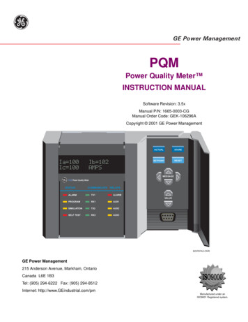
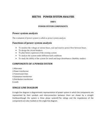
Operational statesNormal state, all system variables are within thenormal rangeAlert state, security level falls below a certain limitof adequacy because of a disturbance generation shifting (security dispatch) , Increased reserveEmergency state, severe disturbance RestorativeAlertIn ExtremisEmergencyfault clearing, generation tripping, load curtailmentIn extremis, cascading outages Normalload shedding and controlled system separationRestorative state, control action is being taken toreconnect all the facilities and to restore systemload.6
Operational requirementFollow the change in the load demandsSupply energy at minimum cost and environmentalimpact.Power quality– Frequency– Voltage– Level of reliability.7
Why constant frequencyFrequency fluctuations are harmful to electricalappliances.– Speed of three phase ac motors proportional to thefrequency. (N 120f/p)– The blades of steam and water turbines are designedto operate at a particular speed. Frequency variationleads to speed variation and results in mechanicalvibration8
Why constant voltageOver voltage and under voltage– Electric motors will tend to run on over speed whenthey are fed with higher voltages resulting vibration andmechanical damage.– Over voltage may also cause insulation failure.– For a specified power rating, lower voltage results inmore current and this results in heating problems.(P VI)9
Control parametersActive Power and Frequency– Balance of load and generation– Load-Frequency ControlReactive Power and Voltage– Automatic voltage regulator– capacitors and reactors– Tap-changing transformers10
Load & generation balanceMatch between electric load and generationFrequency is an indicationBalanced system, 50/60 HzNet power surplus , frequency increasesGenerationLoadNet power shortage, frequency decreasesΔPΔf11
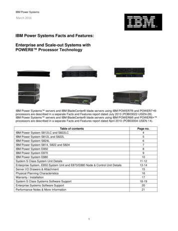
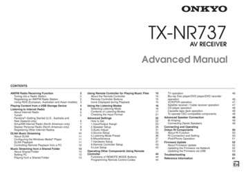
Frequency control actionsGeneration side ControlDemand side controlPrimary ControlΔfGovernorPower SystemdfdtU priUFLSGeneratorfU SecUUFLSΔPtieAGC/LFCΔfSecondary ControlU CTOperatorConnection andTripping of powerEmergency Control12
Primary Frequency Control Generation is controlled bymechanical output of the prime mover The speed governor senses thechange in speed (frequency) Actions taken within 5 – 30 secondsby generator droop control13
Need of primary control reservesUCTE 3000 MW (Continental Europe)–3000 MW or equivalent of two 1500 MW nuclear plants orlines trip at the same timeEastern Interconnection (USA)–3000 MW largest interconnectionNORDEL (North Europe)––Continuous control 600 MW/0.1 HzFrequency response 1000 MW, if frequency drop to49,5 – 49,9 Hz14
Secondary control reservesShould reset the primary control reservesin 5 – 15 minutes to be ready for nextdisturbanceShould correct the frequency deviationwithin allowable limit /- 0.1 Hz in Nordel /- 0.2 Hz in UCTE15
Supplementary/Secondary ControlFrequency deviation feedbackPI or I controllerConnected to economic dispatch system16
Under frequency Load Shedding (UFLS)To prevent extended operation of separated areasat low frequency, load shedding schemes areemployed.A typical scheme for USA: 10% load shed when frequency drops to 59.2 Hz 15% additional load shed when frequency drops to 58.8 Hz 20% additional load shed when frequency reaches 58.0 Hz17
Example18
Voltage ControlControl of voltage levels is carried out by controlling theproduction, absorption, and flow of reactive powerGenerating units provide the basic means of voltagecontrol. synchronous generators– can generate or absorb Q depending on excitation– automatic voltage regulator continuously adjusts excitationto control armature voltage– primary source of voltage support19
Voltage ControlAdditional means are usually required to controlvoltage throughout the system:– sources or sinks of reactive power, such as shuntcapacitors, shunt reactors, synchronous condensers,and static var compensators (SVCs)– line reactance compensators, such as series capacitors– regulating transformers, such as tap-changingtransformers and boosters20
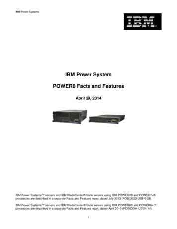
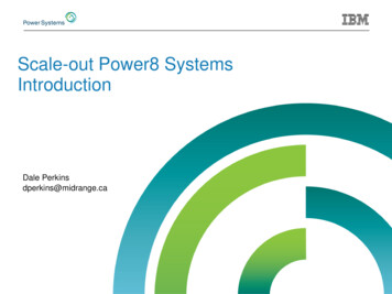
Example: Shunt Compensationa) shunt compensationb) phasor diagram withoutcompensationc) phasor diagram withcompensation21
Introduction to LAB 1Using ARISTO22
Aim of Lab1To introduce–Basic operational phenomena in a typical power system–Corresponding countermeasures–Real time simulations–Dynamic behaviour of power system23
What is ARISTOThe ARISTO system is a fast, interactive power systemdynamics simulator for learning and analysis.The simulator is capable of real-time simulation of largesystems.Simulation of very large systems is possible with a slowersimulation speed.The phenomena to be simulated are: Transient stability. Long term dynamics. Voltage stability.24
System Overview25
What can be modeled?EquipmentLoad Frequency ControlTurbine & Boiler ControlGenerator Excitation ControlSpecial Protection SystemsProtective Relay SystemsHVDC & SVCPhenomenaSub Synchronous ResonanceFrequency VariationsPower SwingHarmonicsSurge10 -410 -310 -210 -11s1010 210 326
Exercises - ScenariosTask 1: Voltage Support Injection / Consumption of reactive powerTask 2: Voltage Collapse in a power system (N-1 Operation) Operation of Line Distance Protection (LDP) relays Islanding of power system due to voltage instabilityTask 3: Frequency control along with load shedding Primary Frequency Control (Governor Droop Characteristics) Secondary Frequency Control (Manual) Under Frequency Load Shedding27
Exercises - Model Simulations are performed with NORDIC 32 test system28
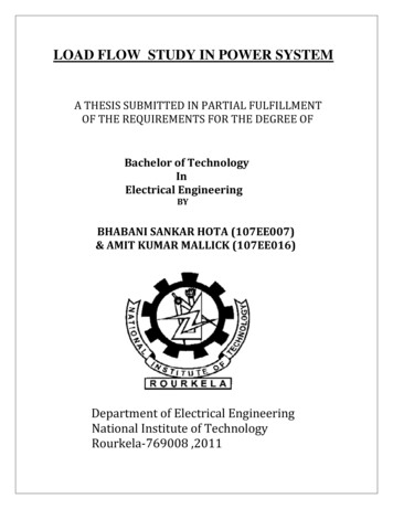
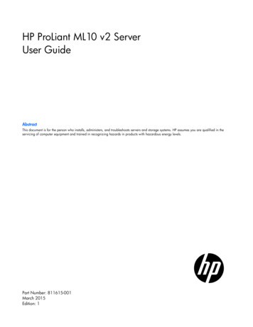
Nordic 32 system descriptionBuses32 Buses21 PV buses, 10 PQ buses, 1 Slack bus19 buses 400kV, 11 buses 135kV, 2 buses 220kVTransmission lines52 Lines33 Lines in 400kV, 17 Lines in 135kVand 2 Lines in 220kVLoads21 buses have loads connected to themNorrActive Production:Active Load:Extern3778 MW-1181 MW1 MWActive Production:Active Load:2301 MW-2300 MW2412 MWSVActive Production:Active Load:340 MW1753 MW-1391 MWMittActive Production:Active Load:3429 MW-6084 MWGenerators39 Generators23 Hydro stations, 15 Thermal Stations and 1 Synchronous compensator21 buses have generatorsShunts22 buses have shunts connected3 buses have both shunt reactors and shunt capacitors11 buses have shunt reactors alone, 8 buses have shunt capacitors alone29
Exercises - Outcome Getting started with ARISTO real time simulator Operation and control of a typical power system Voltage stability Operation of Line Distance Protection (LDP) relays Primary and Secondary Frequency control30
Question?31
system is a fast, interactive power system dynamics simulator for learning and analysis. The simulator is capable of real-time simulation of large systems. Simulation of very large systems is possible with a slower simulation speed. The phenomena to be simulated are: Transient