Transcription
Zynq-7000 SoC:Embedded DesignTutorialA Hands-On Guide to EffectiveSystem DesignUG1165 (2019.2) October 30, 2019See all versionsof this document
Revision HistoryThe following table shows the revision history for this document.DateVersionRevision10/30/20192019.2Added support for the Vitis software platform.11/23/20172017.3Verified for 2017.3 version of Vivado Design Suite, Xilinx SDK, and PetaLinuxTools.Zynq-7000 SoC: Embedded Design TutorialUG1165 (2019.2) October 30, 2019www.xilinx.comSend Feedback2
Table of ContentsRevision History . . . . . . . . . . . . . . . . . . . . . . . . . . . . . . . . . . . . . . . . . . . . . . . . . . . . . . . . . . . . . . . . . . . . 2Chapter 1: IntroductionAbout This Guide . . . . . . . . . . . . . . . . . . . . . . . . . . . . . . . . . . . . . . . . . . . . . . . . . . . . . . . . . . . . . . . . . .How Zynq Devices Simplify Embedded Processor Design . . . . . . . . . . . . . . . . . . . . . . . . . . . . . . . . . .How the Vivado Tools Expedite the Design Process . . . . . . . . . . . . . . . . . . . . . . . . . . . . . . . . . . . . . .What You Need to Set Up Before Starting . . . . . . . . . . . . . . . . . . . . . . . . . . . . . . . . . . . . . . . . . . . . . .5788Chapter 2: Using the Zynq SoC Processing SystemEmbedded System Configuration . . . . . . . . . . . . . . . . . . . . . . . . . . . . . . . . . . . . . . . . . . . . . . . . . . . .Example Project: Creating a New Embedded Project with Zynq SoC . . . . . . . . . . . . . . . . . . . . . . . .Example Project: Running the “Hello World” Application . . . . . . . . . . . . . . . . . . . . . . . . . . . . . . . .Additional Information . . . . . . . . . . . . . . . . . . . . . . . . . . . . . . . . . . . . . . . . . . . . . . . . . . . . . . . . . . . .12132932Chapter 3: Using the GP Port in Zynq DevicesAdding IP in PL to the Zynq SoC Processing System . . . . . . . . . . . . . . . . . . . . . . . . . . . . . . . . . . . . . 34Standalone Application Software for the Design. . . . . . . . . . . . . . . . . . . . . . . . . . . . . . . . . . . . . . . . 50Chapter 4: Debugging with the Vitis Software PlatformXilinx System Debugger . . . . . . . . . . . . . . . . . . . . . . . . . . . . . . . . . . . . . . . . . . . . . . . . . . . . . . . . . . . . 52Debugging Software Using the Vitis Software Platform . . . . . . . . . . . . . . . . . . . . . . . . . . . . . . . . . . 54Chapter 5: Using the HP Slave Port with AXI CDMA IPIntegrating AXI CDMA with the Zynq SoC PS HP Slave Port . . . . . . . . . . . . . . . . . . . . . . . . . . . . . . .Standalone Application Software for the Design. . . . . . . . . . . . . . . . . . . . . . . . . . . . . . . . . . . . . . . .Linux OS Based Application Software for the CDMA System . . . . . . . . . . . . . . . . . . . . . . . . . . . . . .Running Linux CDMA Application Using the Vitis Software Platform . . . . . . . . . . . . . . . . . . . . . . .57626667Chapter 6: Linux Booting and Debug in the Vitis Software PlatformRequirements . . . . . . . . . . . . . . . . . . . . . . . . . . . . . . . . . . . . . . . . . . . . . . . . . . . . . . . . . . . . . . . . . . . . 80Booting Linux on a Zynq SoC Board . . . . . . . . . . . . . . . . . . . . . . . . . . . . . . . . . . . . . . . . . . . . . . . . . . 81Zynq-7000 SoC: Embedded Design TutorialUG1165 (2019.2) October 30, 2019www.xilinx.comSend Feedback3
Chapter 7: Creating Custom IP and Device Driver for LinuxRequirements . . . . . . . . . . . . . . . . . . . . . . . . . . . . . . . . . . . . . . . . . . . . . . . . . . . . . . . . . . . . . . . . . . .Creating Peripheral IP . . . . . . . . . . . . . . . . . . . . . . . . . . . . . . . . . . . . . . . . . . . . . . . . . . . . . . . . . . . .Integrating Peripheral IP with PS GP Master Port . . . . . . . . . . . . . . . . . . . . . . . . . . . . . . . . . . . . . .Linux-Based Device Driver Development . . . . . . . . . . . . . . . . . . . . . . . . . . . . . . . . . . . . . . . . . . . . .Loading Module into Running Kernel and Application Execution . . . . . . . . . . . . . . . . . . . . . . . . .103104109112114Chapter 8: Software Profiling Using the Vitis Software PlatformProfiling an Application in the Vitis Software Platform with System Debugger . . . . . . . . . . . . . . 118Additional Design Support Options . . . . . . . . . . . . . . . . . . . . . . . . . . . . . . . . . . . . . . . . . . . . . . . . . 120Chapter 9: Linux OS Aware Debugging Using the Vitis Software PlatformSetting Up Linux OS Aware Debugging. . . . . . . . . . . . . . . . . . . . . . . . . . . . . . . . . . . . . . . . . . . . . . . 121Debugging Linux Processes and Threads Using OS Aware Debug . . . . . . . . . . . . . . . . . . . . . . . . . 124Appendix A: Additional Resources and Legal NoticesXilinx Resources . . . . . . . . . . . . . . . . . . . . . . . . . . . . . . . . . . . . . . . . . . . . . . . . . . . . . . . . . . . . . . . . .Solution Centers. . . . . . . . . . . . . . . . . . . . . . . . . . . . . . . . . . . . . . . . . . . . . . . . . . . . . . . . . . . . . . . . .Documentation Navigator and Design Hubs . . . . . . . . . . . . . . . . . . . . . . . . . . . . . . . . . . . . . . . . . .Design Files for This Tutorial . . . . . . . . . . . . . . . . . . . . . . . . . . . . . . . . . . . . . . . . . . . . . . . . . . . . . . .Xilinx Resources . . . . . . . . . . . . . . . . . . . . . . . . . . . . . . . . . . . . . . . . . . . . . . . . . . . . . . . . . . . . . . . . .Training Resources. . . . . . . . . . . . . . . . . . . . . . . . . . . . . . . . . . . . . . . . . . . . . . . . . . . . . . . . . . . . . . .Please Read: Important Legal Notices . . . . . . . . . . . . . . . . . . . . . . . . . . . . . . . . . . . . . . . . . . . . . . .Zynq-7000 SoC: Embedded Design TutorialUG1165 (2019.2) October 30, 2019www.xilinx.comSend Feedback1331331331341341351354
Chapter 1IntroductionAbout This GuideThis document provides an introduction to using the Xilinx Vivado Design Suite flow forusing the Zynq -7000 SoC device. The examples are targeted for the Xilinx ZC702 Rev 1.0evaluation board and the tools used are the Vivado Design Suite and the Vitis unifiedsoftware platform.The examples in this document were created using the Xilinx tools running on Windows 7,64-bit operating system, and PetaLinux on Linux 64-bit operating system. Other versions ofthe tools running on other Window installs might provide varied results. These examplesfocus on introducing you to the following aspects of embedded design.Note: The sequence mentioned in the tutorial steps for booting Linux on the hardware is specific tothe PetaLinux tools released for 2019.2, which must be installed on the Linux host machine forexercising the Linux portions of this document.Document Audience and ScopeThe purpose of this guide is to empower software application developers, system softwaredesigners, and system hardware designers by providing the following: Tutorials for creating a system with the Zynq-7000 SoC processing system (PS) and theprogrammable logic (PL) Tutorials on booting the Linux OS on the Zynq SoC board and application developmentwith PetaLinux tools Tutorials on debugging in the Vitis integrated design environment (IDE) System design examplesExample ProjectThe best way to learn a tool is to use it. So, this guide provides opportunities for you towork with the tools under discussion. Specifications for sample projects are given in theexample sections, along with an explanation of what is happening behind the scenes. Eachchapter and examples are meant to showcase different aspects of embedded design. TheZynq-7000 SoC: Embedded Design TutorialUG1165 (2019.2) October 30, 2019www.xilinx.comSend Feedback5
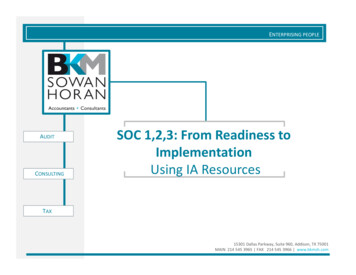
Chapter 1: Introductionexample takes you through the entire flow to complete the learning and then moves on toanother topic.Additional DocumentationVivado Design Suite, System EditionXilinx offers a broad range of development system tools, collectively called the VivadoDesign Suite. Various Vivado Design Suite editions can be used for embedded systemdevelopment. In this guide, you will use the System Edition. The Vivado Design Suiteeditions are shown in the following figure.X-Ref Target - Figure 1-1Figure 1-1:Vivado Design Suite EditionsOther Vivado ComponentsOther Vivado components include:Zynq-7000 SoC: Embedded Design TutorialUG1165 (2019.2) October 30, 2019www.xilinx.comSend Feedback6
Chapter 1: Introduction Embedded/Soft IP for the Xilinx embedded processors Documentation Sample projectsVitis Unified Software PlatformThe Vitis unified software platform is an integrated development environment (IDE) for thedevelopment of embedded software applications targeted towards Xilinx embeddedprocessors. The Vitis software platform works with hardware designs created with VivadoDesign Suite. The Vitis software platform is based on the Eclipse open source. For moreinformation about the Eclipse development environment, see http://www.eclipse.org.PetaLinux ToolsFor more information, see the Embedded Design Tools web page.The PetaLinux Tools design hub provides information and links to documentation specific tothe PetaLinux Tools. For more information, see Embedded Design Hub - PetaLinux Tools.How Zynq Devices Simplify Embedded ProcessorDesignEmbedded systems are complex. Hardware and software portions of an embedded designare projects in themselves. Merging the two design components so that they function asone system creates additional challenges. Add an FPGA design project to the mix, and yourdesign has the potential to become complicated.The Zynq SoC solution reduces this complexity by offering an Arm Cortex -A9 dual core,along with programmable logic, all within a single SoC.To simplify the design process, Xilinx offers the Vivado Design Suite and the Vitis softwareplatform. This set of tools provides you with everything you need to simplify embeddedsystem design for a device that merges an SoC with an FPGA. This combination of toolsoffers hardware and software application design, debugging capability, code execution, andtransfer of the design onto actual boards for verification and validation.Zynq-7000 SoC: Embedded Design TutorialUG1165 (2019.2) October 30, 2019www.xilinx.comSend Feedback7
Chapter 1: IntroductionHow the Vivado Tools Expedite the Design ProcessYou can use the Vivado Design Suite tools to add design sources to your hardware. Theseinclude the IP integrator, which simplifies the process of adding IP to your existing projectand creating connections for ports (such as clock and reset).You can accomplish all your hardware system development using the Vivado tools alongwith IP integrator. This includes specification of the microprocessor, peripherals, and theinterconnection of these components, along with their respective detailed configuration.The Vitis software platform is used for software development, and can be installed and usedwithout any other Xilinx tools installed on the machine on which it is loaded. The Vitissoftware platform can also be used to debug software applications.The Zynq SoC Processing System (PS) can be booted and made to run withoutprogramming the FPGA (programmable logic or PL). However, in order to use any soft IP inthe fabric, or to bond out PS peripherals using EMIO, programming of the PL is required.You can program the PL in the Vitis software platform.For more information on the embedded design process, see the Vivado Design SuiteTutorial: Embedded Processor Hardware Design (UG940) [Ref 5].What You Need to Set Up Before StartingBefore discussing the tools in depth, you should make sure they are installed properly andyour environments match those required for the "Example Project" sections of this guide.Hardware Requirements for this GuideThis tutorial targets the Zynq ZC702 Rev 1.0 evaluation board, and can also be used for Rev1.0 boards. To use this guide, you need the following hardware items, which are includedwith the evaluation board: The ZC702 evaluation board AC power adapter (12 VDC) USB Type-A to USB Mini-B cable (for UART communications) USB Type-A to USB Micro cable for programming and debugging via USB-Micro JTAGconnection SD-MMC flash card for Linux booting Ethernet cable to connect target board with host machineZynq-7000 SoC: Embedded Design TutorialUG1165 (2019.2) October 30, 2019www.xilinx.comSend Feedback8
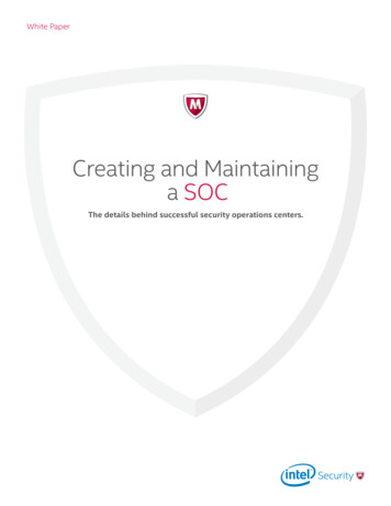
Chapter 1: IntroductionInstallation RequirementsVitis Software Platform and Vivado Design SuiteEnsure that you have both the Vitis software platform and the Vivado Design Suite installed.Visit the Xilinx Support Page to ensure that you download the latest software version. Toinstall the Vitis software platform, follow the instructions in the Installation section of theVitis Embedded Software Development Flow Documentation (UG1400) [Ref 10]. When youinstall the Vitis software platform, the Vivado Design Suite is installed automatically.To install Vivado by itself, see the Vivado Design Suite User Guide: Release Notes, Installation,and Licensing (UG973) [Ref 6].X-Ref Target - Figure 1-2Figure 1-2:Vitis Software Platform 2019.2 Installer - Select Development EnvironmentZynq-7000 SoC: Embedded Design TutorialUG1165 (2019.2) October 30, 2019www.xilinx.comSend Feedback9
Chapter 1: IntroductionPetaLinux ToolsThe PetaLinux tool offers a full Linux distribution which includes the Linux OS as well as acomplete configuration, build, and deploy environment for Xilinx silicon.Install the PetaLinux Tools to run through the Linux portion of this tutorial. PetaLinux toolsrun under the Linux host system running one of the following: Red Hat Enterprise Workstation/Server 7.2, 7.3, 7.4, 7.5 (64-bit) CentOS 7.2, 7.3, 7.4, 7.5 (64-bit) Ubuntu Linux 16.04.3, 16.04.4 (64-bit)This can use either a dedicated Linux host system or a virtual machine running one of theseLinux operating systems on your Windows development platform.When you install PetaLinux Tools on your system of choice, you must do the following: Download PetaLinux software (version 2019.2) from the Xilinx Website. Install the PetaLinux (version 2019.2) release package. Add common system packages and libraries to the workstation or virtual machine. Formore details, see the Installation Requirements from PetaLinux Tools Documentation:Reference Guide (UG1144) [Ref 8].Prerequisites 8 GB RAM (recommended minimum for Xilinx tools) 2 GHz CPU clock or equivalent (minimum of 8 cores) 100 GB free HDD spaceExtract the PetaLinux PackageBy default, the installer installs the package as a subdirectory within the current directory.Alternatively, you can specify an installation path. Run the downloaded PetaLinux installer.Note: Ensure that the PetaLinux installation path is kept short. The PetaLinux build will fail if the pathexceeds 255 characters.bash ./petalinux-v2019.2-final-installer.runPetaLinux is installed in the petalinux-v2019.2-final directory, directly underneaththe working directory of this command. If the installer is placed in the home directory/home/user, PetaLinux is installed in /home/user/petalinux-v2019.2-final.Refer to Chapter 6, Linux Booting and Debug in the Vitis Software Platform for additionalinformation about the PetaLinux environment setup, project creation, and project usageexamples. A detailed guide on PetaLinux Installation and usage can be found in thePetaLinux Tools Documentation: Reference Guide (UG1144) [Ref 8].Zynq-7000 SoC: Embedded Design TutorialUG1165 (2019.2) October 30, 2019www.xilinx.comSend Feedback10
Chapter 1: IntroductionSoftware LicensingXilinx software uses FLEXnet licensing. When the software is first run, it performs a licenseverification process. If the license verification does not find a valid license, the licensewizard guides you through the process of obtaining a license and ensuring that the licensecan be used with the tools installed. If you do not need the full version of the software, youcan use an evaluation license.For installation instructions and information, see the VivadoDesign Suite User Guide: Release Notes, Installation, and Licensing (UG973) [Ref 6].Tutorial Design FilesSee Design Files for This Tutorial, page 134 for information about downloading the designfiles for this tutorial.Zynq-7000 SoC: Embedded Design TutorialUG1165 (2019.2) October 30, 2019www.xilinx.comSend Feedback11
Chapter 2Using the Zynq SoC Processing SystemNow that you have been introduced to the Xilinx Vivado Design Suite, you will beginlooking at how to use it to develop an embedded system using the Zynq -7000 SoCProcessing System (PS).The Zynq SoC consists of Arm Cortex -A9 cores, many hard intellectual propertycomponents (IPs), and programmable logic (PL). This offering can be used in two ways: The Zynq SoC PS can be used in a standalone mode, without attaching any additionalfabric IP. IP cores can be instantiated in fabric and attached to the Zynq PS as a PS PLcombination.Embedded System ConfigurationCreation of a Zynq device system design involves configuring the PS to select theappropriate boot devices and peripherals. To start with, as long as the PS peripherals andavailable MIO connections meet the design requirements, no bitstream is required. Thischapter guides you through creating a simple PS-based design that does not require abitstream.Zynq-7000 SoC: Embedded Design TutorialUG1165 (2019.2) October 30, 2019www.xilinx.comSend Feedback12
Chapter 2: Using the Zynq SoC Processing SystemExample Project: Creating a New Embedded Projectwith Zynq SoCFor this example, you will launch the Vivado Design Suite and create a project with anembedded processor system as the top level.Starting Your Design1. Start the Vivado Design Suite.2. In the Vivado Quick Start page, click Create Project to open the New Project wizard.3. Use the information in the table below to make selections in each of the wizard screens.Wizard ScreenProject NameProject TypeSystem PropertySetting or Command to UseProject nameedt tutorialProject LocationC:/designsCreate Project SubdirectoryLeave this checkedSpecify the type of sources foryour design. You can start withRTL or a synthesized EDIF.RTL ProjectDo not specify sources at thistime check boxLeave this unchecked.Add SourcesDo not make any changes to this screen.Add ConstraintsDo not make any changes to this screen.Default PartSelectBoardsBoardZYNQ-7 ZC702 Evaluation BoardProject SummaryReview the project summary.New Project Summary4. Click Finish. The New Project wizard closes and the project you just created opens in theVivado design tool.Creating an Embedded Processor ProjectPerform the following steps to create an embedded processor project.1. In the Flow Navigator, under IP Integrator, click Create Block Design.Zynq-7000 SoC: Embedded Design TutorialUG1165 (2019.2) October 30, 2019www.xilinx.comSend Feedback13
Chapter 2: Using the Zynq SoC Processing SystemX-Ref Target - Figure 2-1Figure 2-1:Create Block Design ButtonThe Create Block Design wizard opens.2. Use the following information to make selections in the Create Block Design wizard.Wizard ScreenCreate Block DesignSystem PropertySetting or Command to UseDesign Nametutorial bdDirectory Local to Project Specify Source SetDesign Sources3. Click OK.The Diagram window view opens with a message that states that this design is empty. Toget started, you will next add some IP from the catalog.4. Click the Add IP button.5. In the search box, type zynq to find the Zynq device IP options.6. Double-click the ZYNQ7 Processing System IP to add it to the Block Design.The Zynq SoC processing system IP block appears in the Diagram view, as shown inFigure 2-2.Zynq-7000 SoC: Embedded Design TutorialUG1165 (2019.2) October 30, 2019www.xilinx.comSend Feedback14
Chapter 2: Using the Zynq SoC Processing SystemX-Ref Target - Figure 2-2Figure 2-2:Zynq SoC Processing System IP BlockManaging the Zynq7 Processing System in VivadoNow that you have added the processor system for the Zynq SoC to the design, you canbegin managing the available options.1. Double-click the ZYNQ7 Processing System block in the Block Diagram window.Zynq-7000 SoC: Embedded Design TutorialUG1165 (2019.2) October 30, 2019www.xilinx.comSend Feedback15
Chapter 2: Using the Zynq SoC Processing SystemThe Re-customize IP dialog box opens, as shown Figure 2-3. Notice that by default, theprocessor system does not have any peripherals connected.X-Ref Target - Figure 2-3Figure 2-3:Re-Customize IP Dialog Box2. You will use a preset template created for the ZC702 board. In the Re-customize IPwindow, click the Presets button and select ZC702.This configuration wizard enables many peripherals in the Processing System with somemultiplexed I/O (MIO) pins assigned to them as per the board layout of the ZC702board. For example, UART1 is enabled and UART0 is disabled. This is because UART1 isconnected to the USB-UART connector through UART to the USB converter chip on theZC702 board.Note the check marks that appear next to each peripheral name in the Zynq deviceblock diagram that signify the I/O Peripherals that are active.Zynq-7000 SoC: Embedded Design TutorialUG1165 (2019.2) October 30, 2019www.xilinx.comSend Feedback16
Chapter 2: Using the Zynq SoC Processing SystemX-Ref Target - Figure 2-4Figure 2-4:I/O Peripherals with Active Peripherals Identified3. In the block diagram, click one of the green I/O Peripherals. The MIO Configurationwindow opens for the selected peripheral.X-Ref Target - Figure 2-5Figure 2-5:MIO Configuration Window4. Click OK to close the Re-customize IP wizard. Vivado implements the changes that youmade to apply the ZC702 board presets.Zynq-7000 SoC: Embedded Design TutorialUG1165 (2019.2) October 30, 2019www.xilinx.comSend Feedback17
Chapter 2: Using the Zynq SoC Processing SystemIn the Block Diagram window, notice the message stating that Designer assistance isavailable, as shown in the following figure.X-Ref Target - Figure 2-6Figure 2-6:Run Block Automation Link5. Click the Run Block Automation link.The Run Block Automation dialog box opens.Note that Cross Trigger In and Cross Trigger Out are disabled. For a detailed tutorial withinformation about cross trigger set-up, refer to the Vivado Design Suite Tutorial:Embedded Processor Hardware Design (UG940) [Ref 5].6. Click OK to accept the default processor system options and make default pinconnections.Validating the Design and Connecting PortsNow, validate the design.1. Right-click in the white space of the Block Diagram view and select Validate Design.Alternatively, you can press the F6 key.2. A critical error message appears, indicating that the M AXI GP0 ACLK must beconnected.X-Ref Target - Figure 2-7Figure 2-7:Critical Message Dialog Box3. Click OK to clear the message.Zynq-7000 SoC: Embedded Design TutorialUG1165 (2019.2) October 30, 2019www.xilinx.comSend Feedback18
Chapter 2: Using the Zynq SoC Processing System4. In the Block Diagram view of the ZYNQ7 Processing System, locate theM AXI GP0 ACLK port. Hover your mouse over the connector port until the pencil iconappears.5. Click the M AXI GP0 ACLK port and drag to the FCLK CLK0 input port to make aconnection between the two ports.X-Ref Target - Figure 2-8Figure 2-8:ZYNQ7 Processing System with Connection6. Validate the design again to ensure there are no other errors. To do this, right-click inthe white space of the Block Diagram view and select Validate Design.A message dialog box opens and states "Validation successful. There are no errors orcritical warnings in this design."7. Click OK to close the message.8. In the Block Design view, click the Sources tab.9. Click Hierarchy.10. Under Design Sources, right-click tutorial bd and select Create HDL Wrapper.The Create HDL Wrapper dialog box opens. You will use this dialog box to create a HDLwrapper file for the processor subsystem.TIP: The HDL wrapper is a top-level entity required by the design tools.11. Select Let Vivado manage wrapper and auto-update and click OK.12. In the Block Diagram, Sources window, under Design Sources, expandtutorial bd wrapper.Zynq-7000 SoC: Embedded Design TutorialUG1165 (2019.2) October 30, 2019www.xilinx.comSend Feedback19
Chapter 2: Using the Zynq SoC Processing System13. Right-click the top-level block diagram, titled tutorial bd i - tutorial bd(tutorial bd.bd) and select Generate Output Products.The Generate Output Products dialog box opens, as shown in the following figure.X-Ref Target - Figure 2-9Figure 2-9:Generate Output Products Dialog BoxIf you are running the Vivado Design Suite on a Linux host machine, you might seeadditional options under Run Settings. In this case, continue with the default settings.14. Click Generate.This step builds all required output products for the selected source. For example,constraints do not need to be manually created for the IP processor system. The Vivadotools automatically generate the XDC file for the processor sub-system when GenerateOutput Products is selected.15. When the Generate Output Products process completes, click OK.16. In the Block Diagram Sources window, click the IP Sources tab. Here you can see theoutput products that you just generated, as shown in the following figure.Zynq-7000 SoC: Embedded Design TutorialUG1165 (2019.2) October 30, 2019www.xilinx.comSend Feedback20
Chapter 2: Using the Zynq SoC Processing SystemX-Ref Target - Figure 2-10Figure 2-10:Outputs Generated Under IP SourcesSynthesizing the Design, Running Implementation, andGenerating the Bitstream1. You can now synthesize the design. In the Flow Navigator pane, under Synthesis, clickRun Synthesis.X-Ref Target - Figure 2-11Figure 2-11:Run Synthesis Button2. If Vivado prompts you to save your project before launching synthesis, click Save.While synthesis is running, a status circle displays in the upper right-hand window. Thisstatus circle spools for various reasons throughout the design process. The status circlesignifies that a process is working in the background.X-Ref Target - Figure 2-12Figure 2-12:Status BarWhen synthesis completes, the Synthesis Completed dialog box opens.Zynq-7000 SoC: Embedded Design TutorialUG1165 (2019.2) October 30, 2019www.xilinx.comSend Feedback21
Chapter 2: Using the Zynq SoC Processing System3. Select Run Implementation and click OK.Again, notice that the status bar describes the process running in the background. Whenimplementation completes, the Implementation Completed dialog box opens.4. Select Generate Bitstream and click OK.When Bitstream Generation completes, the Bitstream Generation Completed dialog boxopens.5. Click Cancel to close the window.6. After the Bitstream generation completes, export the hardware and launch the Vitis unified software platform.Exporting Hardware to the Vitis Software Platform1. From the Vivado toolbar, select File Export Export Hardware.The Export Hardware dialog box opens. Make sure that the Export to field is set to thedefault option of C:/designs/edt tutorial/.Note: Only check the Include bitstream option if your design has a programmable logicdesign and is bitstream generated. Otherwise, leave it unchecked.2. Click OK.X-Ref Target - Figure 2-13Figure 2-13:Export HardwareTIP: The hardware is exported in a ZIP file ( project wrapper .xsa).3. Launch the Vitis IDE by using the desktop shortcut or by double-clicking theC:\Xilinx\Vitis\2019.2\bin\vitis.bat file. The Eclipse Launcher dialog boxopens.4. Select the workspace location as C:\designs\workspace. Create the workspacefolder if it is not already created.Zynq-7000 SoC: Embedded Design TutorialUG1165 (2019.2) October 30, 2019www.xilinx.comSend Feedback22
Chapter 2: Using the Zynq SoC Processing SystemX-Ref Target - Figure 2-14Figure 2-14:Vitis IDE Eclipse Launcher Dialog Box5. Click Launch. The Vitis integrated design environment (IDE) opens. Click File New Platform Project to create platform project from the output of Vivado Xilinx ShellArchive (XSA).X-Ref Target - Figure 2-15Figure 2-15:Create New Platform Project6. When the New Platform Project dialog box opens, enter the project name ashw platform, as shown in following figure. Keep the Use default location optionchecked. Click Next.Zynq-7000 SoC: Embedded Design TutorialUG1165 (2019.2) October 30, 2019www.xilinx.comSend Feedback23
Chapter 2: Using the Zynq SoC Processing SystemX-Ref Target - Figure 2-16Figure 2-16:Enter Project Name7. Select Create from hardware specification (XSA/DSA). Click Next.8. In the Platform Project Specification window, browse to the hardware specification fileand select the XSA file C:\designs\edt tutorial\tutorial bd wrapper.xsa.When the XSA file is selected, the Software Specification fields (Operating system andProcessor) are updated to standalone and ps7 cortexa9 0 respectively, as shown in thefollowing figure. Click Finish.Zynq-7000 SoC: Embedded Design TutorialUG1165 (2019.2) October 30, 2019www.xilinx.comSend Feedback24
Chapter 2: Using the Zynq SoC Processing SystemX-Ref Target - Figure 2-17Figure 2-17:Software Specification9. The platform project is created. Double-click on Project Explorer platform.spr toview the platform view as shown in the following figure.Zynq-7000 SoC: Embedded Design TutorialUG1165 (2019.2) October 30, 2019www.xilinx.comSend Feedback25
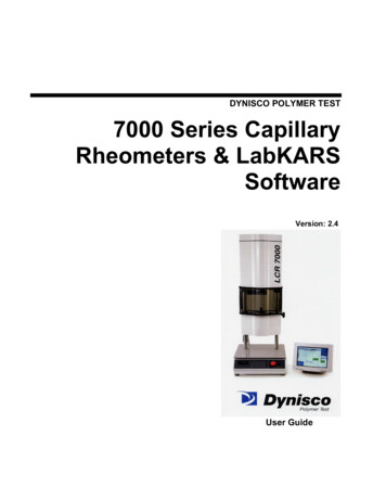
Chapter 2: Using the Zynq SoC Processing System.X-Ref Target - Figure 2-18Figure 2-18:Platform View10. The tutorial bd wrapper.xsa tab shows the address map for the entire processingsystem, as shown in the following figure.Zynq-7000 SoC: Embedded Design TutorialUG1165 (2019.2) October 30, 2019www.xilinx.comSend Feedback26
Chapter 2: Using the Zynq SoC Processing SystemX-Ref Target - Figure 2-19Figure 2-19:Address Map for Processing System11. Build the platform project either by clicking the hammer icon or by right-clicking on theplatform project and selecting Build Project as shown in following figure.X-Ref Target - Figure 2-20Figure 2-20:Zynq-7000 SoC: Embedded Design TutorialUG1165 (2019.
Ubuntu Linux 16.04.3, 16.04.4 (64-bit) This can use either a dedicated Linux host syst em or a virtual machine running one of these Linux operating systems on your Windows development platform. When you install PetaLinux T