Transcription
Digital Image ProcessingSCSVMVDept of ECEDIGITAL IMAGE PROCESSINGLECTURE NOTESB.E (IVYEAR)Prepared byDr.S.VijayaraghavanAssistant Professor-ECESCSVMV Deemed University, KanchipuramPage 1
Digital Image ProcessingSCSVMVDIGITAL IMAGE PROCESSINGDept of ECEVII-SemesterPre-requisite: Basic knowledge of Signals &L T P C4 1 0 4Systems, Digital Signal Processing and DigitalDesignOBJECTIVES: To learn digital image fundamentals. To be exposed to simple image processing techniques. To be familiar with image compression and segmentationtechniques To represent image in form of features.UNIT - I DIGITAL IMAGE FUNDAMENTALSIntroduction – Origin – Steps in Digital Image Processing –Components – Elements of Visual Perception – Image Sensingand Acquisition – Image Sampling and Quantization –Relationships between pixels - color models.UNIT - II IMAGE ENHANCEMENTSpatial Domain: Gray level transformations – Histogramprocessing – Basics of Spatial Filtering–Smoothing andSharpening Spatial Filtering – Frequency Domain:Introduction to Fourier Transform– Smoothing andSharpening frequency domain filters – Ideal, Butterworth andGaussian filters.UNIT - III IMAGE RESTORATION AND SEGMENTATIONNoise models – Mean Filters – Order Statistics – Adaptivefilters – Band reject Filters – Band pass Filters – NotchFilters – Optimum Notch Filtering – Inverse Filtering –Wiener filtering Segmentation: Detection of Discontinuities–Edge Linking and Boundary detection – Region basedsegmentation- Morphological processing- erosion and dilation.Page 2
Digital Image ProcessingSCSVMVDept of ECEUNIT - IV WAVELETS AND IMAGE COMPRESSIONWavelets – Sub band coding – Multi-resolution expansions Compression: Fundamentals – Image Compression models –Error Free Compression – Variable Length Coding – Bit-PlaneCoding – Lossless Predictive Coding – Lossy Compression –Lossy Predictive Coding – Compression Standards.UNIT - V IMAGE REPRESENTATION AND RECOGNITIONBoundary representation – Chain Code – Polygonalapproximation, signature, boundary segments – Boundarydescription – Shape number – Fourier Descriptor, momentsRegional Descriptors – Topological feature, Texture - Patternsand Pattern classes - Recognition based on matching.OUTCOMES:At the end of the course, the student should be able to: Understand the image enhancement techniques Understand the concept of restoration and segmentation Understand wavelets and image compressionTEXT BOOK:1. Rafael C. Gonzales, Richard E. Woods, “Digital ImageProcessing”, Third Edition, Pearson Education, 2010.REFERENCES:1. Rafael C. Gonzalez, Richard E. Woods, Steven L. Eddins, “DigitalImage Processing Using MATLAB”, Third Edition Tata Mc GrawHill Pvt. Ltd., 2011.2. Anil Jain K. “Fundamentals of Digital Image Processing”, PHILearning Pvt. Ltd., 2011.3. Willliam K Pratt, “Digital Image Processing”, John Willey, 2002.4. Malay K. Pakhira, “Digital Image Processing andPattern Recognition”, First Edition, PHI LearningPvt. Ltd., 2011Page 3
Digital Image ProcessingSCSVMVDept of ECEUNIT-1DIGITAL IMAGE FUNDAMENTALS1.2.3.4.LEARNING OBJECTIVES:This unit provides an overview of the image –processing system whichincludes various elements like image sampling, quantization, Basic stepsin image processing, image formation, storage and display. Aftercompleting this unit, the reader is expected to be familiar with thefollowing concepts:Image samplingImage sensorsDifferent steps in image processingImage formationDIGITAL IMAGE FUNDAMENTALS:The field of digital image processing refers to processing digital images bymeans of digital computer. Digital image is composed of a finite number ofelements, each of which has a particular location and value. Theseelements are called picture elements, image elements, pels and pixels.Pixel is the term used most widely to denote the elements of digitalimage.An image is a two-dimensional function that represents a measure of somecharacteristic such as brightness or color of a viewed scene. An image is aprojection of a 3- D scene into a 2D projection plane.Page 4
Digital Image ProcessingSCSVMVDept of ECEAn image may be defined as a two-dimensional function f(x,y), where x andy are spatial (plane) coordinates, and the amplitude tofat any pair ofcoordinates (x,y) is called the intensity of the image at thatpoint. The termgray levelis used often to refer to the intensity of monochrome images.Color images are formed by a combination of individual 2-D images. Forexample, the RGB color system, a color image consists of three (red, greenand blue) individual component images. For this reason, many of thetechniques developed for monochrome images can be extended to colorimages by processing the three component images individually.An image may be continuous with respect to the x- and y- coordinates andalso in amplitude. Converting such an image to digital form requires thatthe coordinates, as well as the amplitude, be ATIONS OF DIGITAL IMAGE PROCESSING:Since digital image processing has very wide applications and almost all ofthe technical fields are impacted by DIP, we will just discuss some of themajor applications of DIP.Digital image processing has a broad spectrum of applications, such asRemote sensing via satellites and otherspacecraftsImage transmission and storage for businessapplicationsMedicalprocessingRADAR (Radio Detection and Ranging)SONAR (Sound Navigation and Ranging)Acoustic Image Processing (The study of underwater sound is known asUnderwater AcousticsorHydroAcoustics)Robotics and automated inspection of industrial partsImages acquired by satellites are useful in trackingofEarthresourcesGeographical mappingPrediction of agriculturalcropsUrban growth and weathermonitoringFlood and fire control and many other environmentalapplicationsSpace image applicationsinclude:Recognition and analysis of objects contained in images obtained from deepspace-probemissions.Image transmission and storage applications occur in broadcasttelevisionTeleconferencingTransmission of facsimile images (Printed documents and graphics) foroffice automationCommunication over computer networksPage 5
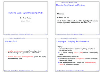
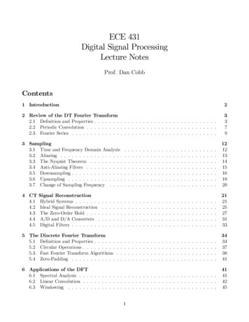
Digital Image ProcessingSCSVMVDept of ECE6. Closed-circuit television-based security monitoring systemsand7. In s:Processing of chest X-raysCineangiogramsProjection images of trans axial tomographyandMedical images that occur in radiology nuclear magneticresonance (NMR)UltrasonicscanningIMAGE PROCESSING TOOLBOX (IPT):It is a collection of functions that extend the capability of the MATLABnumeric computing environment. These functions, and the expressivenessof the MATLAB language, make many image-processing operations easy towrite in a compact, clear manner, thus providing an ideal softwareprototyping environment for the solution of image processingproblem.COMPONENTS OF IMAGE PROCESSING SYSTEM:Fig: Components of Image processing SystemImage Sensors: With reference to sensing, two elements are required toacquire digital image. The first is a physical device that is sensitive to thePage 6
Digital Image ProcessingSCSVMVDept of ECEenergy radiated by the object we wish to image and second is specializedimage processing hardware.Specialize Image Processing Hardware: It consists of the digitizer justmentioned, plus hardware that performs other primitive operations suchas an arithmetic logic unit, which performs arithmetic such addition andsubtraction and logical operations in parallel onimages.Computer: It is a general-purpose computer and can range from a PC to asupercomputer depending on the application. In dedicated applications,sometimes specially designed computer is used to achieve a required levelof performanceSoftware: It consists of specialized modules that perform specific tasks awell-designed package also includes capability for the user to write code, asa minimum, utilizes the specialized module. More sophisticated softwarepackages allow the integration of these modules.Mass Storage: This capability is a must in image processing applications.An image of size 1024 x1024 pixels, in which the intensity of each pixel isan 8- bit quantity requires one Megabytes of storage space if the image isnot compressed. Image processing applications falls into three principalcategories of storage. Short term storage for use duringprocessing On line storage for relatively fastretrieval Archival storage such as magnetic tapes anddisksImage Display: Image displays in use today are mainly color TV monitors.These monitors are driven by the outputs of image and graphics displayscards that are an integral part of computer system.Hardcopy Devices: The devices for recording image include laser printers,film cameras, heat sensitive devices inkjet units and digital units such asoptical and CD ROM disk. Films provide the highest possible resolution,but paper is the obvious medium of choice for written applications.Networking: It is almost a default function in any computer system in usetoday because of the large amount of data inherent in image processingapplications. The key consideration in image transmission bandwidth.Page 7
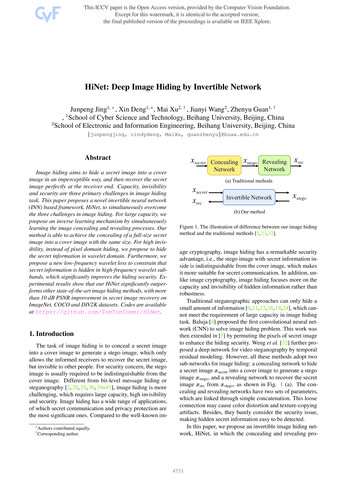
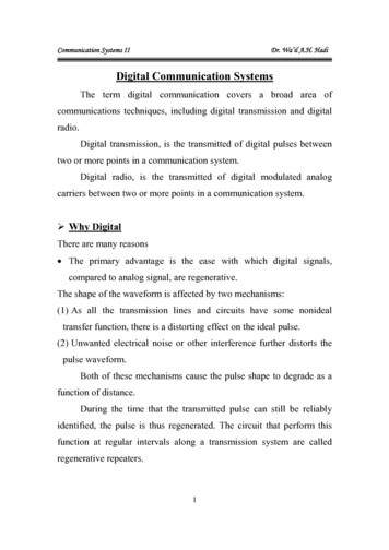
Digital Image ProcessingSCSVMVDept of ECEFUNDAMENTAL STEPS IN DIGITAL IMAGE PROCESSING:There are two categories of the steps involved in the image processing –1. Methods whose outputs are input areimages.2. Methods whose outputs are attributes extracted from thoseimages.Fig: Fundamental Steps in Digital Image ProcessingImage Acquisition: It could be as simple as being given an image that isalready in digital form. Generally, the image acquisition stage involvesprocessing such scaling.Image Enhancement: It is among the simplest and most appealing areas ofdigital image processing. The idea behind this is to bring out details thatare obscured or simply to highlight certain features of interest in image.Image enhancement is a very subjective area of imageprocessing.Image Restoration: It deals with improving the appearance of an image. Itis an objective approach, in the sense that restoration techniques tend tobe based on mathematical or probabilistic models of image processing.Enhancement, on the other hand is based on human subjective preferencesPage 8
Digital Image ProcessingSCSVMVDept of ECEregarding what constitutes a “good” enhancement result.Color Image Processing: It is an area that is been gaining importancebecause of the use of digital images over the internet. Color imageprocessing deals with basically color models and their implementation inimage processingapplications.Wavelets and Multiresolution Processing: These are the foundation forrepresenting image in various degrees of resolution.Compression: It deals with techniques reducing the storage required tosave an image, or the bandwidth required to transmit it over the network.It has to major approaches1. Lossless Compression2. Lossy CompressionMorphological Processing: It deals with tools for extracting imagecomponents that are useful in the representation and description of shapeand boundary of objects. It is majorly used in automated inspectionapplications.Representation and Description: It always follows the output ofsegmentation step that is, raw pixel data, constituting either the boundaryof an image or points in the region itself. In either case converting the datato a form suitable for computer processing is necessary.Recognition: It is the process that assigns label to an object based on itsdescriptors. It is the last step of image processing which use artificialintelligence of software.Knowledge Base: Knowledge about a problem domain is coded into animage processing system in the form of a knowledge base. This knowledgemay be as simple as detailing regions of an image where the information ofthe interest in known to be located. Thus, limiting search that has to beconducted in seeking the information. The knowledge base also can bePage 9
Digital Image ProcessingSCSVMVDept of ECEquite complex such interrelated list of all major possible defects in amaterials inspection problem or an image database containing highresolution satellite images of a region in connection with change detectionapplication.Simple Image Model: An image is denoted by a two dimensional function ofthe form f{x, y}. The value or amplitude of f at spatial coordinates {x,y} is apositive scalar quantity whose physical meaning is determined by thesource of the image. When an image is generated by a physical process, itsvalues are proportional to energy radiated by a physical source. As aconsequence, f(x,y) must be nonzero and finite; that is o f(x,y) co Thefunction f(x,y) may be characterized by two components- The amount of thesource illumination incident on the scene beingviewed.The amount of the source illumination reflected back by the objects in thescene These are called illumination and reflectance components and aredenoted by i(x,y) an r (x,y) respectively.The functions combine as a product to form f(x,y). We call the intensity of amonochrome image at any coordinates (x,y) the gray level (l) of the imageat that point l f (x, y.)L min l Lmax Lminis to be positive and Lmax must be finiteLmin iminrminLmax imaxrmaxThe interval [Lmin, Lmax] is called gray scale. Common practice is to shiftthis interval numerically to the interval [0, L-l] where l 0 is consideredblack and l L-1 is considered white on the gray scale. All intermediatevalues are shades of gray of gray varying from black towhite.SAMPLING AND QUANTIZATION:To create a digital image, we need to convert the continuous sensed datainto digital from. This involves two processes – sampling and quantization.An image may be continuous with respect to the x and y coordinates andalso in amplitude. To convert it into digital form we have to sample thefunction in both coordinates and in amplitudes.Digitalizing the coordinate values is called Sampling. Digitalizing theamplitude values is called Quantization. There is a continuous the imagealong the line segment AB. To simple this function, we take equally spacedsamples along line AB. The location of each samples is given by a verticaltick back (mark) in the bottom part. The samples are shown as blocksquares superimposed on function the set of these discrete locations givesthe sampled function.Page 10
Digital Image ProcessingSCSVMVDept of ECEIn order to form a digital, the gray level values must also be converted(quantized) into discrete quantities. So, we divide the gray level scale intoeight discrete levels ranging from eight level values. The continuous graylevels are quantized simply by assigning one of the eight discrete graylevels to each sample. The assignment it made depending on the verticalproximity of a simple to a vertical tick mark. Starting at the top of theimage and covering out this procedure line by line produces a twodimensional digitalimage.Digital ImageDefinition: A digital image f(m,n) described in a 2D discretespace is derived from an analog image f(x,y) in a 2D continuous spacethrough a sampling process that is frequently referred to as digitization.The mathematics of that sampling process will be described in subsequentChapters. For now, we will look at some basic definitions associated withthe digital image. The effect of digitization is shown in figure.The 2D continuous image f(x,y) is divided into N rows and M columns. Theintersection of a row and a column is termed a pixel. The value assigned tothe integer coordinates (m,n) with m 0,1,2.N-1 and n 0,1,2 N-1 isf(m,n). In fact, in most cases, is actually a function of many variablesincluding depth, color and time (t).There are three types of computerized processes in the processing of imageLow level Process: These involve primitive operations such as imageprocessing to reduce noise, contrast enhancement and image sharpening.These kinds of processes are characterized by fact the both inputs andoutput areimages.Mid-levelImage Processing: It involves tasks like segmentation,description of those objects to reduce them to a form suitable for computerprocessing, and classification of individual objects. The inputs to theprocess are generally images but outputs are attributes extracted fromimages.High level Processing: It involves “making sense” of an ensemble ofrecognized objects, as in image analysis, and performing the cognitivefunctions normally associated with vision.Page 11
Digital Image ProcessingSCSVMVDept of ECERepresenting Digital Images: The result of sampling and quantization ismatrix of real numbers. Assume that an image f(x,y) is sampled so that theresulting digital image has M rows and N Columns. The values of thecoordinates (x,y) now become discrete quantities thus the value of thecoordinates at origin become (x,y) (0,0) The next Coordinates value alongthe first signify the image along the first row. it does not mean that theseare the actual values of physical coordinates when the image was sampled.Thus, the right side of the matrix represents a digital element, pixel or pel.The matrix can be represented in the following form as well. The samplingprocess may be viewed as partitioning the XY plane into a grid with thecoordinates of the center of each grid being a pair of elements from theCartesian products Z2 which is the set of all ordered pair of elements (Zi, Zj)with Zi and Zj being integers from Z.Hence f(x,y) is a digital image ifgray level (that is, a real number from theset of real number R) to each distinct pair of coordinates (x,y). Thisfunctional assignment is the quantization process. If the gray levels arealso integers, Z replaces R, the and a digital image become a 2D functionwhose coordinates and she amplitude value are integers. Due to processingstorage and hardware consideration, the number gray levels typically arean integer power of 2.kL 2Then, the number ‘b’ of bites required to store a digital image isb M *N* kWhen M N, the equation become2b N *kWhen an image can have 2k gray levels, it is referred to as “k- bit”. An8image with 256 possible gray levels is called an “8- bit image” (256 2 ).Spatial and Gray level Resolution:Spatial resolution is the smallest discernible details are an image. Supposea chart can be constructed with vertical lines of width w with the spacePage 12
Digital Image ProcessingSCSVMVDept of ECEbetween the also having width W, so a line pair consists of one such lineand its adjacent space thus. The width of the line pair is 2w and there is1/2w line pair per unit distance resolution is simply the smallest number ofdiscernible line pair unitdistance.Gray levels resolution refers to smallest discernible change in gray levels.Measuring discernible change in gray levels is a highly subjective processreducing the number of bits R while repairing the spatial resolutionconstant creates the problem of false contouring.It is caused by the use ofan insufficient number of gray levels on the smooth areas of the digitalimage. It is called so because the rides resemble top graphics contours in amap. It is generally quite visible in image displayed using 16 or lessuniformly spaced gray levels.Image Sensing and Acquisition: The types of images in which we areinterested are generated by the combination of an “Illumination” sourceand the reflection or absorption of energy from that source by the elementsof the “scene” being imaged. We enclose illumination and scene in quotes toemphasize the fact that they are considerably more general than thefamiliar situation in which a visible light source illuminates a commoneveryday 3-D (three-dimensional) scene.For example, the illumination may originate from a source ofelectromagnetic energy such as radar, infrared, or X-ray energy. But, asnoted earlier, it could originate from less traditional sources, such asultrasound or even a computer-generated illumination pattern. Similarly,the scene elements could be familiar objects, but they can just as easily ouldevenimageasource,suchasacquiringimages of the sun. Depending on the nature of the source, illuminationenergy is reflected from, or transmitted through, objects.An example in the first category is light reflected from a planar surface. AnPage 13
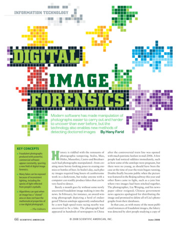
Digital Image ProcessingSCSVMVDept of ECEexample in the second category is when X-rays pass through a patient’sbody for the purpose of generating a diagnostic X-ray film. In someapplications, the reflected or transmitted energy is focused onto a photoconverter (e.g., a phosphor screen), which converts the energy into visiblelight.Electron microscopy and some applications of gamma imaging use thisapproach. The idea is simple: Incoming energy is transformed into avoltage by the combination of input electrical power and sensor materialthat is responsive to the particular type of energy being detected. Theoutput voltage waveform is the response of the sensor(s), and a digitalquantity is obtained from each sensor by digitizing its response. In thissection, we look at the principal modalities for image sensingandgeneration.Fig: Line SensorFig: Single Image SensorThe components of a single sensor, perhaps the most familiar sensor of thistype is the photodiode, which is constructed of silicon materials and orexample, a green (pass) filter in front of a light sensor favors light in thegreen band of the color spectrum. As a consequence, the sensor output willbe stronger for green light than for other components in the visiblespectrum.Page 14
Digital Image ProcessingSCSVMVDept of ECEFig: Array sensor Image Acquisition using a Single SensorIn order to generate a 2-D image using a single sensor, there has to berelative displacements in both the x- and y-directions between the sensorand the area to be imaged. Figure shows an arrangement used in highprecision scanning, where a film negative is mounted onto a drum whosemechanical rotation provides displacement in one dimension. The singlesensor is mounted on a lead screw that provides motion in theperpendicular direction. Since mechanical motion can be controlled withhigh precision, this method is an inexpensive (but slow) way to obtainhigh-resolution images. Other similar mechanical arrangements use a flatbed, with the sensor moving in two linear directions. These types ofmechanical digitizers sometimes are referred to as microdensitometers.Image Acquisition using a Sensor Strips:A geometry that is used much more frequently than single sensors consistsof an in-line arrangement of sensors in the form of a sensor strip, shows.The strip provides imaging elements in one direction. Motionperpendicular to the strip provides imaging in the other direction. This isthe type of arrangement used in most flatbed scanners. Sensing deviceswith 4000 or more in-line sensors are possible. In-line sensors are usedroutinely in airborne imaging applications, in which the imaging system ismounted on an aircraft that flies at a constant altitude and speed over thegeographical area to be imaged. One dimensional imaging sensor stripsthat respond to various bands of the electromagnetic spectrum aremounted perpendicular to the direction of flight. The imaging strip givesone line of an image at a time, and the motion of the strip completes theother dimension of a two-dimensional image. Lenses or other focusingschemes are used to project area to be scanned onto the sensors. Sensorstrips mounted in a ring configuration are used in medical and industrialimaging to obtain cross-sectional (“slice”) images of 3-Dobjects.Page 15
Digital Image ProcessingSCSVMVDept of ECEFig: Image Acquisition using linear strip and circular stripsImage Acquisition using a Sensor Arrays:The individual sensors arranged in the form of a 2-D array. Numerouselectromagnetic and some ultrasonic sensing devices frequently arearranged in an array format. This is also the predominant arrangementfound in digital cameras. A typical sensor for these cameras is a CCDarray, which can be manufactured with a broad range of sensing propertiesand can be packaged in rugged arrays of elements or more. CCD sensorsare used widely in digital cameras and other light sensing instruments.The response of each sensor is proportional to the integral of the lightenergy projected onto the surface of the sensor, a property that is used inastronomical and other applications requiring low noise images. Noisereduction is achieved by letting the sensor integrate the input light signalover minutes or even hours. The two dimensional, its key advantage is thatPage 16
Digital Image ProcessingSCSVMVDept of ECEa complete image can be obtained by focusing the energy pattern onto thesurface of the array. Motion obviously is not necessary, as is the case withthe sensor arrangements This figure shows the energy from anillumination source being reflected from a scene element, but, asmentioned at the beginning of this section, the energy also could betransmitted through the scene elements. The first function performed bythe imaging system is to collect the incoming energy and focus it onto animage plane. If the illumination is light, the front end of the imagingsystem is a lens, which projects the viewed scene onto the lens focal plane.The sensor array, which is coincident with the focal plane, producesoutputs proportional to the integral of the light received at each sensor.Digital andanalog circuitry sweeps these outputs and convert them to avideo signal, which is then digitized by another section of the imagingsystem.Image sampling and Quantization:To create a digital image, we need to convert the continuous sensed datainto digital form. This involves two processes.1. Sampling and2. QuantizationA continuous image, f(x, y), that we want to convert to digital form. Animage may be continuous with respect to the x- and y- coordinates, andalso in amplitude. To convert it to digital form, we have to sample thefunction in both coordinates and in amplitude.Digitizing the coordinate values is called Sampling. Digitizing theamplitude values is called Quantization.Fig: SamplingPage 17
Digital Image ProcessingSCSVMVDept of ECEFig: QuantizationDigital Image Representation:Digital image is a finite collection of discrete samples (pixels) of anyobservable object. The pixels represent a two- or higher dimensional “view”of the object, each pixel having its own discrete value in a finite range. Thepixel values may represent the amount of visible light, infra-red light,absorption of x-rays, electrons, or any other measurable value such asultrasound wave impulses. The image does not need to have any visualsense; it is sufficient that the samples form a two-dimensional spatialstructure that may be illustrated as an image. The images may beobtained by a digital camera, scanner, electron microscope, ultrasoundstethoscope, or any other optical or non-optical sensor.Examples of digital image areDigitalphotographs, Satelliteimages,Radiological images (x-rays, mammograms), Binary images, Fax images,Engineeringdrawings, Computer graphics, CAD drawings, and vectorgraphics in general are not considered in this course even though theirreproduction is a possible source of an image. In fact, one goal ofintermediate level image processing may be to reconstruct a model (Eg:Vector Representation) for a given digital image.Relationship between Pixels:We consider several important relationships between pixels in a digitalimage.Neighbors of a Pixel:A pixel p at coordinates (x,y) has four horizontal and verticalneighborswhose coordinates are givenby:(x 1,y), (x-1, y), (x, y 1), (x,y-1)This set of pixels, called the 4-neighbors or p, is denoted by N4(p). EachPage 18
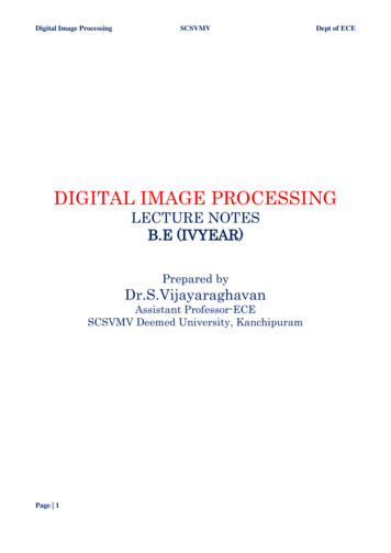
Digital Image ProcessingSCSVMVDept of ECEpixel is one unit distance from (x,y) and some of the neighbors of p lieoutside the digital image if (x,y) is on the border of the image. The fourdiagonal neighbors of p have coordinates and are denoted by ND(p).(x 1, y 1), (x 1, y-1), (x-1, y 1), (x-1, y-1).These points, together with the 4-neighbors, are called the 8-neighbors ofp, denoted by N8(p).As before, some of the points in ND(p) and N8(p) fall outside the image if(x,y) is on the border of the image.Adjacency and Connectivity:Let v be the set of gray –level values used to define adjacency, in a binaryimage, V {1}. In a gray-scale image, the idea is the same, but Vtypicallycontains more elements, for example, V {180, 181, 182, ,200}.If the possible intensity values 0 – 255, Vset can be any subset of these 256values. if we are reference to adjacency of pixel with value.Three types of Adjacency:4- Adjacency – two pixel P and Q with value from V are 4 –adjacency if A isin the setN4(P)8- Adjacency – two pixel P and Q with value from V are 8 –adjacency if A isin the set N8(P)Page 19
Digital Image ProcessingSCSVMVDept of ECEM-adjacency –two pixel P and Q with value from V are m – adjacency if (i)Q is in N4(p) or(ii) Q is in ND(q) and the(iii) Set N4(p) N4(q) has no pixel whose values are fromV.Mixed adjacency is a modification of 8-adjacency. It is introduced toeliminate the ambiguities that often arise when 8-adjacency isused.Forexample:Fig: (a) Arrangement of pixels(b) pixels that are 8-adjacent (shown dashed) to the center pixel(c) m-adjacencyTypes of Adjacency:In this example, we can note that to connect between two pixels (finding apath between twopixels):In 8-adjacency way, you can find multiple paths between twopixelsWhile, in m-adjacency, you can find only one path between twopixelsSo, m-adjacency has eliminated the multiple path connection that has beengenerated by the8-adjacency.Two subsets S1 and S2 are adjacent, if some pixel in S1 is adjacent to somepixel in S2. Adjacent means, either 4-, 8- orm-adjacency.Digital Path:A digital path (or curve) from pixel p with coordinate (x,y) to pixel q withcoordinate (s,t) is a sequence of distin
To learn digital image fundamentals. . (Printed documents and graphics) for office automation 5. Communication over computer networks . . Computer: It is a general-purpose computer and can range from a PC to a supercomputer