Transcription
CHAPTER ONEBefore You Begin1.1 INTRODUCTIONIn order to execute the piping designs of a project efficiently, it isessential that you initially identify and address all of the prerequisites thatmust be in place for the piping designers to start work. In order to dothis you must first recognize all the questions that must be asked andanswered, assemble all the needed tools, and make decisions accordingly.As you progress in your career you will find that this ability is requiredfor any project, and that the best piping leads are those who can createmissing tools when the need arises.The intent of this chapter is to provoke your thought process: itfocuses on the questions to ask and the tools required in order to begin aproject. Do you have everything you need to proceed?A first step is to assemble and then make yourself familiar with theengineering company and/or client standards, specifications, and procedures to be used on the project. Larger clients will have certain requirements in place and mandate that those requirements be used on theproject, whereas smaller clients will likely default entirely to the engineering company. Generally speaking, all projects will use a combination ofengineering company and client standards, specifications, and procedures.You must ensure that you know which you are using and where theycome from. As a piping lead it is doubly important to familiarize yourselfwith these requirements, not just so you can guide your team, butbecause you will likely have to explain your design basis to other departments and sometimes even to the client themselves. It is also up to you toinsist that they be respected and adhered to, or that a formal deviation beapproved by the client. On this note, you must inform yourself of thedeviation procedure to be used on the project. Examples of standards are as follows: Standard fabrication and installation details/drawings such as shoedesign and base ell supports.The Planning Guide to Piping Design.DOI: -5 2018 Elsevier Inc.All rights reserved.1
2The Planning Guide to Piping Design Drawing standards such as layering, text heights, and drawing symbols. Charts such as line spacing within racks. Examples of specifications are piping classes, equipment spacingrequirements, and egress and ingress requirements (walkways, platforms, and ladders). Examples of procedures are drawing reviews, model reviews, checking, and as-builting.Below are some brief explanations of standards, specifications, and procedures, and their most likely sources. There are no guarantees, so you willhave to investigate each in turn. As we progress into further chapters wewill highlight these in more detail, discuss the importance of decision making at an early stage, and discuss the links between the topics. Once youhave investigated, assembled, and made all your decisions, you are ready togo, and you have set yourself on a path toward a successful piping execution. By the time you have completed your initial set-up you will have agreater understanding of the project, the expectations, and how you willachieve those expectations. Knowing the reasons behind all of the decisionsyou have made or helped to make will put you in a position to recognizewhen things are going wrong, and will aid greatly later in correcting them.1.2 STANDARDSTo determine whether the standards to be used are going to comefrom your own company or your client, you must consult with your project management team and the client.Standards include the following: Standard drawings Charts Drawing templates and drawing standards Drawing numbering 3D model numbering Material commodity codes1.2.1 Standard drawingsStandard drawings are typical fabrication and installation details of commonly encountered items. These are assigned a tag number for easy reference on the piping arrangements and isometrics. The use of a standard
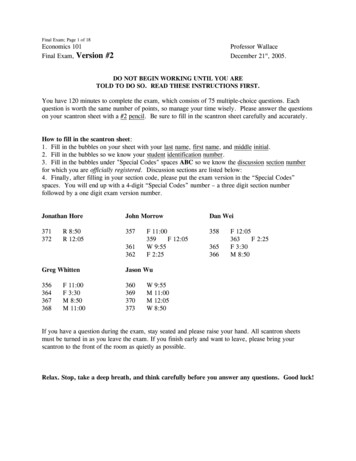
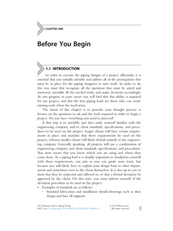
Before You Begin3avoids detailing the same thing time after time. Commonly, standarddrawings are as follows: Shoes Anchors: fixed and directional Guides Base ell supports Dummy legs Trunnions Field supports Reinforcing pads Slide plates Tracing details Insulation details Instrument connection details Orifice tap orientations Block and bleed details Vents and drains Utility Stations Heat Trace ManifoldsWhere suitable, a standard will cover more than one Nominal PipeSize (NPS), so that one fit for purpose design may be used on a range ofpipe sizes. For instance, all companies will have shoe designs that willcover a range similar to the ones below: NPS 6 and under NPS 8 to NPS 12 NPS 14 to NPS 18 NPS 20 to NPS 24You will find that companies mercilessly plagiarize from each other,and most likely you will recognize standards that you have used before asyou move from one company to another. You may even see a standardthat you created or helped to create being used by another company.Examples of standards are shown in Figs. 1.1 1.7.1.2.2 ChartsThere are three charts that are the most important to the piping designersand must be in place: Branch connection (can vary by piping class and may be includedwithin the piping classes) Line spacing Line spanning
4The Planning Guide to Piping DesignFigure 1.1 Dummy leg.Examples of these are shown in Tables 1.1 1.4.While line spacing charts and branch connection charts are fairlystraightforward, care must be taken with line spanning charts. Line spanning charts will provide layout guidance, but many load factors may affectthe posted spans. Final pipe spans must be confirmed during stress analysis.While not vital, a chart worthy of adding to the above list is that fornozzle projection. Projections (distance from the surface of a vessel ortank to the face of the flanges) vary with nozzle size, flange rating, insulation thickness, and reinforcing pad thickness. The minimum projection
Before You Begin5Figure 1.2 Trunnion support.allows for approximately 3 in. (76 mm) of pipe length between the shelland a weld neck flange. This length is required for welding and removalof stud bolts. An example of a Nozzle Projection Chart is Table 1.5.A nozzle chart is useful for discussion with the mechanical group andstudy work prior to the receipt of vendor drawings.1.2.3 Drawing templates and drawing standardsDrawing templates are required for the drawings that are to be created forthe project. There are four common drawing templates for four plot sizesdepending on drawing type and/or scale factor:
6The Planning Guide to Piping Design Figure 1.3 Base support. ANSI paper sizes used in the United States and Canada: A size—81/2v 3 11v (e.g., standards). B size—11v 3 17v (e.g., construction isometrics). D size—22v 3 34v (e.g., Process Flow Diagrams (PFDs), Pipingand Instrumentation Diagrams (P&IDs), and piping arrangements). E size—34v 3 44v (e.g., plot plans, equipment location plans, andkey plans).
Before You Begin7Figure 1.4 Pipe shoe. ISO A series paper sizes used in the rest of the world: A4—210 mm 3 297 mm (e.g., standards). A3—297 mm 3 420 mm (e.g., isometrics). A1—594 mm 3 841 mm (e.g., PFDs, P&IDs, and pipingarrangements). A0—841 mm 3 1189 mm (e.g., plot plans, equipment locationplans, and key plans).
8The Planning Guide to Piping DesignFigure 1.5 Directional anchor NPS 6 and under.ANSI C (17v 3 22v) and ISO A2 (420 mm 3 594 mm) paper sizesare usually reserved for reduced size plots of ANSI D and E, and ISO A1and A0. This is due to being a convenient handling size while retaining alarge enough drawing size for clarity and mark-ups.It is most likely that the client will have drawing templates for threeof the four drawing sizes, ANSI A, D, and E, or ISO A4, A1, and A0,that they will require you to use on their project. For the constructionisometric template, ANSI B/ISO A3, the client will most often defer tothe engineering company. This is because, unlike the other drawings,
Before You Begin9Figure 1.6 Directional anchor NPS 8 to NPS 12.construction isometrics are not usually issued to future engineering companies to be revised on future projects. After project close-out, these isometrics commonly become for-information-only historical recordsretained for reference only, negating the need for client drawing templateand drawing numbering formats. Additionally, on projects utilizing 3DCAD, engineering companies routinely incorporate a construction isometric template linked to the database for data extraction (e.g., data fromthe Line Designation Tables, LDT) as part of their CAD set-up.Drawing templates have predetermined drawing standards as part oftheir set-up, so that when a drawing is plotted, the text heights, lineweights, etc., will be to the correct dimensions.
10The Planning Guide to Piping DesignFigure 1.7 Single block vent and drain.Drawing standards include the following: Titleblock with company logo Text heights Layering system Line weights Dimension stylesA client requirement to be investigated is the filling in of the titleblock. The document management software used by the client may be setup to scrub meta-data from the attributes in the 2D CAD file and for this
Table 1.1 Branch connections process lines
12The Planning Guide to Piping DesignTable 1.2 Branch connections instrument and utility airreason many clients have strict instruction on exactly how certain information is to be typed in. For instance, drawing titles may have to bearranged on three or four lines of text in a particular order (e.g.,Operating Area/Plant Name/Plant Area/Drawing Description) and certain characters and formats may be governed (e.g., date format of DD/MM/YYYY or MM-DD-YYYY).Other forms of drawing standards that you will require are drawingsymbols legend sheets and drafting abbreviations. Primarily, the legendsheets you will require are going to be the PFD and P&ID legend sheetsfrom the client that contain all the approved symbols to be used on thedrawings. Drafting abbreviations come from various industry organizations, e.g., ANSI, ASME, and ISA. The most commonly used ones areoften summarized as a company standard. See Appendix A for an exampleof drafting abbreviations used on piping drawings.1.2.4 Drawing numberingCommonly, with the exception of the construction isometrics, clientshave drawing numbering requirements. Each client mandates the drawingnumbering to be used. File numbering, which ideally should equate to
Table 1.3 Line spacing chart
Table 1.4 Line spanning chart
15Before You BeginTable 1.5 Nozzle projection chartFlange class ratingMin. outside projectionfrom shell 200250300350400500550All dimensions are in mm.Dimensions do not include insulation or reinforcing pad thicknesses.the drawing number, is also mandated in order for the client to be able toaccept the drawing files back into the document management system andbe able to retrieve them when required. While numbering systems varyby company, most have a hierarchy numbering system using abbreviatedidentifiers along the following lines: Area of operation Facility Discipline, e.g., mechanical, piping Type of drawing, e.g., piping arrangement Three- or four-digit sequential drawing number Two- or three-digit sequential sheet numberIsometric drawing numbering will require separate investigation. Anoften used practice is to include the line number as part of the drawingnumber for easy identification. Sheet numbers identify longer runs wherea piping system has been broken into multiple isometric details for clarity,e.g., SHT 1 OF 5, SHT 2 OF 5,. . . . .SHT 5 OF 5.1.2.5 3D model numberingWhat is the model numbering convention to be used for the project?Again, this may be a client or engineering company standard, but it must
16The Planning Guide to Piping Designbe decided right at the beginning of the project. If you are directed touse a company standard, make sure that your client is in agreement.These models will later have to be closed-out and renumbering/renamingcan cause considerable work that is likely not included in the budget. Aswith drawing file numbering, models require a file numbering systemthat is approved by the client. In today’s 3D integrated design world,where all disciplines are referencing the other disciplines’ models, andworking more-or-less in real time, you and your designers must intimately know the model numbering system. This is in order to correctlyname the piping models and identify other disciplines’ models that arerequired to be referenced.One way that I have seen model numbering done is to follow theEngineering Work Package (EWP) numbering. This makes sense becauseassembling information is not just the domain of the designers. Often theCAD support group or the material control group will be requested togenerate reports of a particular EWP, or a group of EWPs, and a common numbering system for the models and the EWPs will help to locateand compile the information. Common reports are as follows: Material Take Off (MTO), either bulk or item specific for pipe and fittings insulation valves shop material (also known as fabrication material) field material (also known as erection material) Weld count and diameter inches of welding Weights of materialsAs all of the reports are generated from the databases that are built asthe models are developed, having a direct correlation to the EWP number makes life easier for the downstream people, such as material controllers and purchasers.1.2.6 Material commodity codesMaterial commodity codes are a piping component numbering systemused for the identification, ordering, and tracking of materials.Originating in the 3D model material library database, these numbersappear on the MTO reports and the isometric Bills of Material (BOM)and in the documentation used by the purchasers, suppliers, fabricators,and warehousing. These codes are commonly an alpha-numeric string
Before You Begin17(e.g., “F” for flange) which uniquely identifies a component. AlthoughISO 15926 is making inroads, industry standards do not currently existfor material commodity coding of piping components, so companies haveto develop their own key element identifiers or engage the services of anoutside consultant to develop these for them. So why should this be aconcern for the piping lead? If you are using your company piping classesand the material commodity coding is in place, then for the most partyou and your designers will have no interest in material commodity codesother than curiosity. However, if material commodity codes are to beused on the project, and development is required because your companydoes not currently have a commodity coding system, or the client wantsyou to use their commodity coding system, then you will need to takeinto consideration the time involved for the development and implementation by the material control group and IT. Development and implementation can impact your ability to start 3D modeling.As not all projects use material commodity codes, you will have toascertain whether they are to be used on your project or not. If they are,are they to be to your company’s standards or the client’s? Will the adoption of a commodity code numbering system cause you any delays?1.3 SPECIFICATIONSMany clients and engineering companies will have a set of companyspecifications for each discipline built on code, safety and insurancerequirements, and preferred engineering practices. Most specifications areengineering related, but some are directly related to the layout of theplant. As has already been said, these are related to walkways, platformand ladder requirements, egress and ingress, and equipment spacing, butthey often also include other information of importance to the pipingdesigners such as pump and exchanger piping layouts, and transportationrequirements for modules and spools. As the lead, you must review theseand catalog for your team all of the pertinent specifications and wherethey may be found, commonly on the company network or a client webbased site.The most obvious and essential specifications to be secured are thepiping classes.
18The Planning Guide to Piping Design1.3.1 Piping classesThe piping classes are one of the most important specifications for thepiping designer. These are developed by the piping engineer, and mostoften have been applied on numerous projects, sometimes for many years.Piping classes are developed around the applicable piping code, and listcomponents and materials manufactured to the standards listed within thecode. This allows component use with no further investigation and avoidscalculations and material selections being repeated time and time againfor the same application. The piping classes list the following: ASME code (B31.1 in power plants and B31.3 in process plants) Fluid service (process commodities) Flange rating Corrosion allowance Temperature range Pressure limits Non-Destructive Examination (NDE) Heat treatment NPS range, and pipe schedule wall thickness (WT) or calc. wall End preparation Valves Listed standards/components and materials accepted by the code for pipe fittings flanges orifice flanges unions plugs nipples spectacle blinds, spades, and spacers olets gaskets boltingAn example of a piping class is Table 1.6.Piping classes have an abbreviated identifier. An example of this is thefollowing three-digit identifier and Table 1.7: Flange rating Service Pipe material
Before You Begin19Components manufactured to standards not listed in the code, or notfabricated to a standard, are not listed within the piping classes. These areknown as unlisted or specialty items (SP) and they are listed in the specialty item list. These include such items as strainers and expansion joints.In order to be used within the piping system, specialty items must conform to the engineering and testing requirements set out in the code.Neither do piping classes take into account out-of-spec items such asa flat face flange needed in a raised face piping system to match with apump casing flange or Class 300 flanges needed in a Class 150 system tomatch with the instrumentation.On 3D CAD projects designers will have to request that these out-ofspec items be added to the piping class material database on a case-bycase basis (given that instruments such as control valves are verycommonly specified to a minimum of Class 300 to accommodate theTable 1.6 Example piping class
20Table 1.6 ContinuedThe Planning Guide to Piping Design
Before You BeginTable 1.6 Continued21
22The Planning Guide to Piping DesignTable 1.6 Continuedinstrument weight with a reduced potential for flange leakage, it is appropriate that all Class 150 specifications databases be prebuilt with optionalClass 300 flanges).As requesting the addition of out-of-spec items can be a source offrustration for both the piping designer making the request and thematerial controller receiving the request, you will require an approvalprocedure for adding out-of-spec components into the piping classeslibraries. The piping designers’ concerns center on the time required forrequest completion and possible reluctance to add a component.Likewise, material controllers have valid concerns about adding components that appear unnecessary. As this can result in conflict and given thatneither of them own the piping classes, it is highly recommended that all
Before You Begin23Table 1.7 Piping class identifiersrequests be vetted through the piping engineer for approval; the pipingengineer is the custodian of the piping classes, and is the appropriate person for the authorization and expedition of changes and additions.Calculated wall, or “calc. wall” as it is often listed in the piping classes,is another subject to be addressed by yourself and the piping engineer assoon as possible. If you start the modeling with the calculated wall it canlater become a problem to update the models once the pipe schedulehas been determined. This is particularly true when a piping class encompasses several process commodities and the NPS ranges of pipe vary incalculated WT according to the differing design conditions.I strongly suggest that you discuss this sooner rather than later withthe piping engineer and the material controller. I also strongly suggestthat the calculated wall be based on the worst case design conditions forthe piping class. The potential for mistakes in design, fabrication, andmaterial control when WT choices exist for a given pipe size can outweigh any cost saving that may be realized on the pipe and fittings themselves. It is also possible that a calculated pipe schedule may prove to beless commercially available than a slightly heavier pipe schedule. Schedule160, for instance, is usually very available, whereas Schedule 140 usuallyis not as available.Finally, the set-up of the piping classes for the use by the designerswhen creating the 3D models is a joint exercise between the materialcontrol group who create the database content and the CAD supportgroup who ensures the functionality. Prior to the start of modeling you
24The Planning Guide to Piping Designmust have these piping classes databases checked against the original(likely in Word format) specifications. The accuracy of all MTO reportsand BOM lists on the isometrics rests on the accuracy of the piping classdatabases and the importance of ensuring the integrity of these databasescannot be overstated.Having said this, it is also strongly recommended that the pipingdesigners be required to habitually refer back to the original specifications.An impression exists on 3D projects that reference to the original pipingclasses and branch charts is unnecessary because the choices of availablecomponents, including branch fitting choices, have been predetermined andlimited per the piping class databases. This is to say that the belief is that thedatabases provide all the information needed about the allowable pipingcomponents (spec driven). However, mistakes in set up and checking dohappen, and as a safeguard all your designers should be held accountable tounderstand the root documents and to verify differing information.Once the piping classes have been approved they are frozen for theduration of the project. Changes may happen to the piping classes duringthe project, but these must follow a deviation process.1.4 PROCEDURESProjects revolve around procedures, and without these you cannotexecute your project. Procedures are the “Highway Code” that keepseveryone on the same page. However, procedures are often either poorlywritten or not enforced, which is as bad as having no procedure. Readthe procedures thoroughly and understand them, because it will be up toyou to enforce them later, and possible to expand on them.Engineering company procedures will commonly include thefollowing: Stick files Interdiscipline drawing reviews, both internal (engineered drawings)and vendor Line numbering Stress analysis CAD set-up and support 3D model reviews Checking
Before You Begin25 Manhour estimatingProgress reportingManagement of changeClient procedures have been developed to standardize the drawingand model deliverables. These include the following: Drawings to be as-built Project close-outThese last two procedures are usually owned by your client’s documentmanagement department and enforced by your own company’s documentmanagement. That does not mean though that you do not have a say.These procedures have areas of overlapping accountabilities betweendesigners and document controllers. Because no procedure is perfect for allsituations, the client’s document management department is most oftenconducive to small deviations and are willing to work with you from adesigner’s input point of view. On smaller projects you may well havedirect access to speak with them, whereas on larger projects you will haveto request a deviation through your project management team. Deviationsto client procedures identified during the initial set-up should be documented in the Project Execution Plan (PEP). You will need to inform yourproject management team of all deviations to the document managementprocedures initiated by yourself and agreed to by the client.The following are brief discussions on all the above-mentioned procedures/activities that you, as a piping lead, must be aware of, and that thepiping group has a direct or indirect involvement in. In Chapter Two,CAD and Design Automation in Piping Design, we will discuss in moredetail the procedures below that the piping group manage directly orhave a major involvement in.1.4.1 Stick filesWhether electronic computer based or in hard copy paper format, a stickfile is the best tool to use for capturing and managing changes. It is a central depository for all mark-ups from all disciplines and ensures that allchanges are clearly communicated and surprises are avoided.The trend in recent years has been to do everything in an electroniccomputer based environment and shun hard copy paper formats as inefficient and undesirable in the context of project record keeping. This is aperfect example of where the worlds of manual and electronic procedureshave collided. While possible to utilize an electronic stick file procedure
26The Planning Guide to Piping Designusing a mark-up tool such as Adobe Reader or Bluebeam Revu, in practice it is still very much human nature to defer to marking up a hardcopy print of a drawing due to this still being easier and more familiar.I advocate that a hard copy stick file is still best, scanned prior to backdrafting for record.A decision will need to be made on either an electronic or a manualstick file procedure.If electronic is the choice, then you will need to know where the drawings are to be deposited and how they are to be accessed and edited withmark-ups. You will also need to receive alerts when comments are made.Similarly, if manual is the choice, you will need to have a procedurearound mark-ups and notification, and you will need to identify an areawhere your master stick files will reside. Preferably this will be close byand with reference tables to lay the stick files on. Ideally, you will haveroom for roller boards. Roller boards, where the drawings are tapped down,work wonderfully to stop people wandering off with your stick files.1.4.2 Interdiscipline drawing reviewsDrawings are produced in every project. Drawings represent the culmination of the design, and a finalization of all discussions and decisions todate. A review by all disciplines that have had input is required in orderto establish that the designs are as expected by all stakeholders. It is youraccountability to ensure that the piping drawings are made available forreview and comment. Likewise to master stick files, interdiscipline drawing reviews may be by electronic or hard copy methods, either throughnetwork access or hard copy circulation. Electronic reviews require a network place where the drawings are stored. Hard copy reviews require acirculation procedure and filing cabinets for storage. Both review methodsrequire a way of sending notifications to the reviewers.Vendor drawings also require a review procedure. While you are notresponsible for initiating vendor drawing reviews, you are responsible toensure the integrity and availability of the latest vendor drawings forreference and mark-up by your team.Regardless of the interdiscipline drawing review procedure employed,the document control group play a key role. You will need to liaise withthe document control lead for an understanding of their processes and toensure that your needs are going to be met. In the case of electronicmark-ups, it may also be needed to arrange training for your team on thedocument control software.
Before You Begin271.4.3 Line numberingLine numbering is a standard. The elements that make up a line numberand the order of placement are standardized by each client or engineeringcompany. The sequencing of the elements may change between companies, but all line numbers contain the following: Piping class NPS Sequential line number Insulation thickness and type Tracing requirementsSome standards may also include the following: Unit number Commodity abbreviation of the process fluidWhen it comes to the task of assigning line numbers to the P&IDs, aprocedure is required. Does a line reduction within a header system constitute the assignment of another line number? Is a pump suction line thatsplits to a pair of A and B pumps two or three line numbers? You willdiscover that there are different thoughts on the subject. Line numberingmay not be the responsibility of the piping group, and it may fall underthe auspices of the process engineers’, but you as a piper have a vestedinterest that requires discussion. The overuse of line numbers can result inpiping runs being broken down into a greater number of isometrics.Whoever does it, and to whatever procedure, line numbering needsto be done sooner rather than later, as modeling cannot begin withoutline numbers having been assigned.1.4.4 Stress analysisHow are you going to interface with the stress group? Which lines willbe stressed first? How will you track stress analysis? Where will you storethe stress mark-ups? And how will the stress requirements be disseminatedto the pipers? These are questions that we will investigate in more detailin Chapter Two, CAD and Design Automation in Piping Design. It is acomplex matter, and not one to be overlooked. If you do not have acompany procedure to fall back on, you will need to develop one.1.4.5 CAD set-upCAD support is a major contrib
Isometric drawing numbering will require separate investigation. An often used practice is to include the line number as part of the drawing number for easy identification. Sheet numbers identify longer runs where a piping system has been broken into multiple isometric details f