Transcription
LECTURE NOTESONMOBILE COMPUTINGSUBJECT CODE: PECS 5301 (3-0-0)PREPARED BYDR. PRASHANTA KUMAR PATRACOLLEGE OF ENGINEERING AND TECHNOLOGY, BHUBANESWAR
PECS5301 MOBILECOMPUTING (3-0-0)Module - I 10 HrsIntroduction to Personal Communications Services (PCS) : PCS Architecture, mobilitymanagement, Networks signaling, Global System for Mobile Communication (GSM) Systemoverview : GSM Architecture, Mobility management, Network signaling.General Packet Radio Services (GPRS): GPRS Architecture, GPRS Network Nodes, MobileData Communication; WLANs (Wireless LANs) IEEE 802.II standard, Mobile IP.Module - II 14 HrsWireless Application Protocol (WAP): The Mobile Internet standard, WAP Gateway andProtocols, wireless mark up Languages (WML), Wireless Local Loop (WLL) : Introduction toWLL Architecture, wireless Local Loop Technologies.Third Generation (3G) Mobile Services: Introduction to International MobileTelecommunications 2000 (IMT 2000) Vision, Wideband Code Division Multiple Access (WCDMA), and CDMA 2000Module - III 12 HrsGlobal Mobile Satellite Systems ; case studies of the IRIDIUM, ICO and GLOBALSTARsystems. Wireless Enterprise Networks : Introduction to Virtual Networks, Blue toothtechnology, Blue tooth Protocols.Server-side programming in Java, Pervasive web application architecture, Deviceindependent example application.Text Books:1. Mobile Communication: J. Schiller, Pearson Education2. Mobile Computing: P.K. Patra, S.K. Dash, Scitech Publications.nd3. Mobile Computing: Talukder, TMH, 2 Edition.Reference Books:1. Pervasive Computing: Burkhardt, Pearson Education.nd2. Principles of Mobile Computing: Hansmann, Merk, Springer, 2 Edition.3. Wireless Communication & Networking: Garg, Elsevier4. Third Generation Mobile Telecommunication Systems: P. Stavronlakis, Springer.5. The Wireless Application Protocol: Sandeep Singhal, Pearson Education
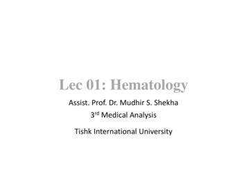
Module-IPCS (Personal Communication System)PCS stands for Personal Communication System. The objective of PCS is to enablecommunication with a person at any time, at any place & in any form. It also managestheir individual call services according to their service by providing unlimited reachability& accessibility.Sprint was the first company to set up a PCS network, which was a GSM-1900 networkin the Baltimore-Washington metropolitan area in the USA. PCS promises to provide awide range of locations and equipment-independent services to a large number ofusers. According to the definition given by the US Federal CommunicationsCommission (FCC), PCS is the system by which every user can exchange informationwith everyone, at anytime, in any place, through any type of services, using a singlepersonal telecommunication number (PTN).Key factors of PCS are:1. Reachability with respect to Location (Home, office, in public, in transit)1. Accessibility with respect to Device (Cellular phone, wired phone, fax etc.)2. Management of ServiceArchitectureArchitecture consists of two partsRadio NetworkPCS users carry mobile stations (MS) to communicate with a BS in a PCS n/w. MS isalso referred to as handset or mobile phone. The radio coverage of a base station is
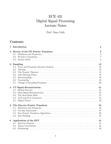
called cell. In GSM n/w each cell is controlled by BSC which are connected to MSthrough BS. The BSCs are connected to MSC by landlines.Wireline Transport NetworkAn MSC is a telephone exchange configured specially for mobile applications. Itinterfaces the MSC (via BS) with PSTN. MSCs are also connected with mobilitydatabase to track the location of MS and roaming management. The databases areHLR & VLR. HLR contains the authentication information like IMSI (International MobileSubscriber Identity), identification information like name, address of the subscriber,billing information like prepaid or postpaid, operator selection, denial of service to asubscriber etc. VLR gives information about the location area of the subscriber while onroaming and power off status of the handset.Fig 5.1 PCS network Architecture5.4 Mobility ManagementMobility mgmt function handles the function that arises due to mobility of the subscriber.
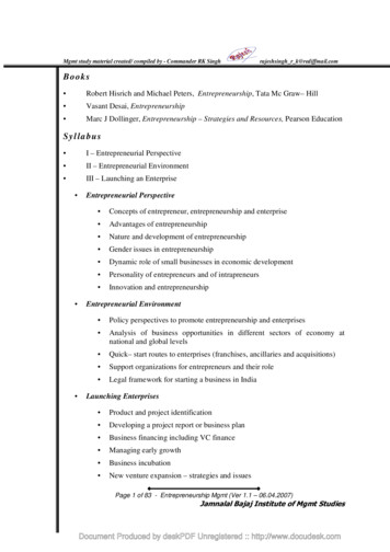
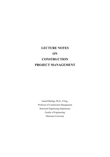
Main objective of MM is location tracking & call set up. There are two aspects of mobilityin a PCS n/w.HANDOFF: When a mobile user is engaged in conversation, the MS is connected to BSvia radio link. If the user moves to the coverage area of another BS, the radio link to oldBS is disconnected and radio link to new BS is established to continue conversation.This process is called automatic link transfer or handoff. Depending on the mobility ofMS, the handoff is divided into two categories:Inter-BS Handoff/ Inter Cell Handoff:Here MS usually moves from one BS to another BS under one MSC.Action taken for communication:1. The MS momentarily suspends conversation & initiates the hand-off procedureby picking a channel in new BS. Then is resumes the conversation in old BS.2. When MSC receives that signal, he transfers the information to the new BS &sets up new conversation path to MS through that channel.3. After MS has been transferred to new BS, it starts the conversation channel withnew BS & then MSC disconnect the link with old BS.MSCOld BSNew BS(a) Step 1MSCOld BSMSCNew BS(b) Step 2Old BSMSCNew BSOld BS(c) Step 3Fig 5.2 Inter-BS link TransferInter-System Handoff/Inter-MSC HandoffMS moves from one BS to another connected to two different MSCs.(d) Step 4New BS
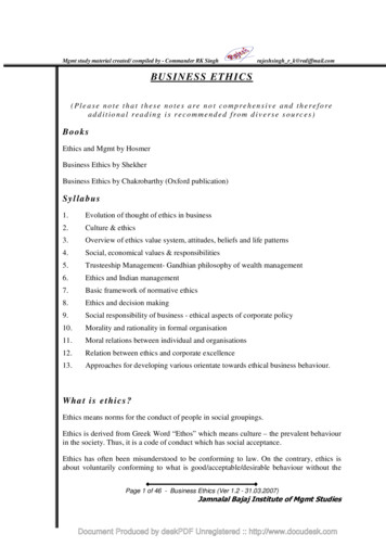
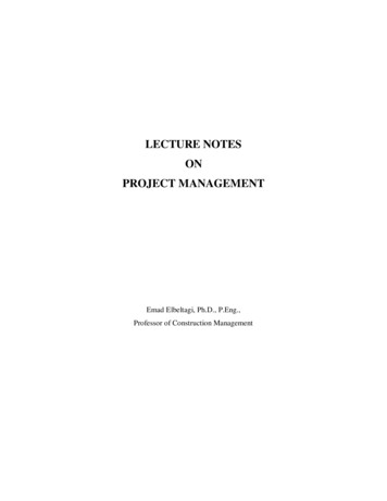
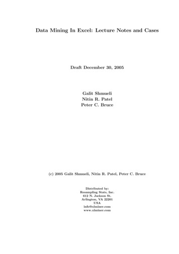
Action taken for communication:1. MSC1 requests MSC2 to perform handoff measurement on the call in progress.2. MSC2 then selects a BS by interrogating the signal quality and sends theinformation to MSC1.3. Then MSC1 asks MSC2 to setup a voice channel.4. Assuming that a voice channel is available in BS2.MSC2 instructs MSC1 to startradio link transfer.5. MSC1 sends the MS a handoff order. Now MS can access BS2 of MSC2.MSC2informs MSC1 that handoff is successful.MSC1 then connects call path to MSC2.6. In the intersystem handoff process, anchor MSC is always in call path before &after SC2MSC2BS2MSC2Fig 5.3 Inter System HandoffPath Minimization- When MS moves to MSC3, MSC2 may be removed from the callpath. The link between MSC1 and MSC2 is disconnected and MS connects to MSC3directly. This process is called path minimization.
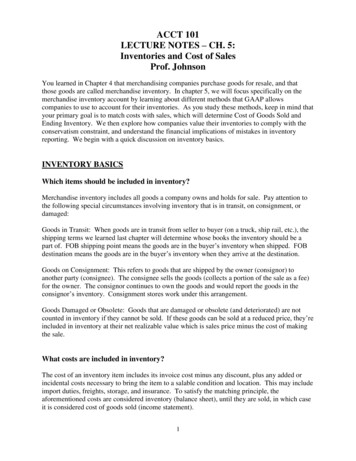
MSC1MSC2MSC1MSMSFig 5.4 Handoff ForwardMSC2MSC2Fig 5.5 Handoff BackwardMSC3MSC2MSC1MSC1MSC3MSMSFig 5.6Hand-off to 3rdFig 5.7 Path minimizationROAMING: When a mobile user moves from one PCS system to another, then thesystem should be informed of the current location of the user. Otherwise it is impossibleto deliver services.Two basic operations are performed under roaming management.1. Registration (location update): Where MS informs the system its currentlocation.2. Location tracking: Process during which a system locates MS. Locationtracking is required when n/w attempts to deliver call to a mobile user.The roaming management follows a two level strategy where two tier systems of homeand visited databases are used. When a user subscribes to the services of a network, arecord is created in the system’s database called HLR. This is referred to as home
system of the mobile user. HLR is a n/w database, where MS's identity, profile, currentlocation & validation period is stored.When the mobile user visits a new network other than home system, a temporaryrecord for the mobile user is created in the VLR of visited system. VLR temporarilystores information for visiting subscribers so that corresponding MSC can provideservice.Registration Procedure includes following steps:1. When mobile user enters into new PCS n/w, it must register in VLR of newsystem.2. The new VLR informs mobile user's HLR regarding the current location &address of user. The HLR sends an acknowledgement which includes MS'sprofile, to the new VLR.3. New VLR informs MS about successful registration.4. HLR sends a deregistration message to cancel the location record of MS in oldVLR. The old VLR acknowledges the deregistration.Visitor Location RegisterNEWVLR13Home Location Register2HLR4OLDVLRMorristown New JersyNew York City,New YorkLos Angels, CaliforniaFig 5.8 MS registration ProcessTo originate a call, MS first contacts with MSC in the new PCS n/w .The call request isforwarded to VLR for approval. If it is approved, MSC sets up the call to the userfollowing the standard PSTN procedures.
1. If a wireline phone attempts to call a mobile subscriber, the call is forwarded toswitch called the originating switch in PSTN. The switch masses a query to HLRto find current VLR of MS. The HLR queries the VLR in which MS resides to geta communicable address.2. The VLR returns the address to switch through HLR.3. Based on address, a communication link is established between MS throughvisited MSC.1PSTN1HLR223VLRMSC31Fig 5.9 Call Delivery ProcedureGSM(Global System for Mobile Communication)GSM is the most popular standard for mobile phones in the world. GSM (Global Systemfor Mobile communication) is a digital mobile telephony system that is widely used inEurope and other parts of the world.In 1982, the European Conference of Postal and Telecommunications Administrations(CEPT) created the Groupe Spécial Mobile (GSM) to develop a standard for a mobiletelephone system that could be used across Europe. In 1989, GSM responsibility wastransferred to the European Telecommunications Standards Institute (ETSI) and phase Iof the GSM specifications were published in 1990.
The first GSM network was launched in 1991 by Radiolinja in Finland with joint technicalinfrastructure maintenance from Ericsson. The proposed GSM system had to meetcertain business objectives: Support for International Roaming Good Speech Quality Ability to support handheld terminals Low terminal and service cost. Spectral EfficiencyGSM uses a combination of FDMA and TDMA. The GSM system has an allocation of50 MHz bandwidth in the 900 MHz frequency band. Using FMA, this band is divided into124 channels each with a carrier bandwidth of 200 KHz. Using TDMA, each of thesechannels is further divided into 8 time slots. Therefore with combination of FDMA andTDMA we can realize a maximum of 992 channels for transmit and receive.Cell: Cell is the basic service area: one BTS covers one cell. Each cell is given aCell Global Identity (CGI), a number that uniquely identifies the cell.Location Area: A group of cells form a Location Area. This is the area that is pagedwhen a subscriber gets an incoming call. Each Location Area is assigned a LocationArea Identity (LAI). Each Location Area is served by one or more BSCs.GSM Architecture
Fig 6.1 GSM Architecture overviewAbbreviationsMSC :Mobile switching centerBSC :Base station controllerBTS :Base transceiver stationTRX :Transceiver.MS :Mobile stationOMC:Operations and Maintenance centre.PSTN:BSS :Base station sub-system.HLR :Home location registerVLR :Visitor locations registerPublic switched telephone network.
AUC :Authentication centreEIR :Equipment Identity Register.GSM network can be divided into 4 groups.MS (Mobile Station)An MS is used by a mobile subscriber to communicate with the mobile network. Severaltypes of MSs exist, each allowing the subscriber to make and receive calls.Manufacturers of MS offer a variety of design and features to meet the need of differentmarket.The mobile station consists of: Mobile Equipment (ME) Subscriber identity module (SIM)Fig 6.2 GSM Mobile TerminalME (Mobile Equipment)“Cellular phone without SIM card”The mobile equipment has a unique international mobile equipment identity (IMEI)which is used by EIR. The numbers of GSM terminal types are defined within the GSMspecification. They are distinguished primarily by their power output rating. The range orcoverage area of an MS is dependent on the output power capabilities and
consequently different ranges. For example, hand held MSs have a lower output powerand shorter range than car-installed MSs with a roof mounted antennaSIM (Subscriber Identity Module)SIM card used in phones are smart processor cards. It possesses a processor and asmall memory. The SIM stores permanent and temporary data about the mobile, thesubscriber and the network. It contains a serial no, PIN, PUK (Pin Unblocking Key),an authentication key (Ki), IMSI (International Mobile Subscriber Identity).The SIM can be plugged into any GSM mobile terminal. This brings the advantages ofsecurity and portability for subscriber. Example: Subscriber A’s mobile terminal mayhave been stolen. However, A’s own SIM can be used in another person’s mobileterminal and the calls will be charged to subscriber A.Functions of MSFunction of MS is transmission of signal from MS to BTS (using uplink) and reception ofsignal from BTS to MS (using down link).BSS (Base Station Subsystem)BSS contains two components: BTS BSCBTS (Base Transceiver Station)It comprises all radio equipments (e.g.: antenna, signal processing & amplifier requiredfor transmission).It is placed in the center of a cell. Its transmitting power defines thesize of a cell. It is connected to MS via Um interface and connected to BSC via AbisInterface. It manages the radio resources for BTSs. It handles & handover the radiofrequency, radio channel set up from one BTS to other.BSC (Base Station Controller)
It connects the BTS and MSC of NSS. It manages radio resources for one or more BTS.It handles and Handover the radio frequency, radio channel setup from one BTS toanother.Fig 6.3 BSC & BTS Arrangement in GSM SystemNSS (Network Switching Subsystem)The NSS combines the call rotating switches (MSC and GMSC) with data baseregistered required to keep track of subscriber’s movements and use of the system. Keyelements of NSS are: MSC VLR HLRMSC (Mobile Switching Centre)
The mobile-services switching centre is an exchange which performs all the switchingand signaling functions for mobile stations located in a geographical area designated asthe MSC area. These are high performance digital ISDN switches. It is used forconnection between mobile phone to mobile phone within same network. It is used forconnection between mobile phone to fixed phone within a network. It manages BSCwithin a geographical area.GMSC (Gateway MSC)Connection for another network MSC handles all the signaling needed for connectionset up and connection release.HLR (Home Location Register)The HLR is a centralized network data base that stores and manages all mobileservices belonging to a specific operator. It acts as a permanent store for a person’ssubscription information until that subscription is cancelled. It provides call routing androaming facility by combining with MSC and VLR. It is considered as a Database whichstores the information about the subscriber within covering area of MSC. Informationincludes current location of the mobile & all the service providing information, when aphone is powered off this information is stored in HLR. It is also a database but containsa temporary copy of some of important information stored in HLR. If a new MS usercomes into location area, then VLR will provide relevant information by bringing it fromHLR.VLR (Visitor Location Resister)It is a temporary storage device of GSM network. It stores subscribers’ subscriptioninformation for MS which are within the particular MSC service Area. There is one VLRfor each MSC service areaOSS (Operation and Support Subsystem)It contains necessary function for network operation and maintenance.Key Elements are OMC
EIR AUCOMC (Operation and maintenance center)It is connected to different components of NSS & to BSC. It controls the traffic load ofBSS.EIR (Equipment Identity Register)A database that contains a list of all valid mobile equipment within the network whereeach MS is identified by IMEI (International Mobile Equipment Identity).EIR contains alist of IMEI of all valid terminals. An IMEI is marked invalid if it is stolen. EIR allows theMSC to forbid calls from this stolen terminal. The equipment identification procedureuses the identity of the equipment itself (IMEI) to ensure that the MS terminal equipmentis valid.AUC (Authentication Center)It is defined to protect user identity & transmission. It is a protected database and storesa copy of secret information stored in SIM card .These data help to verify user’s identity.Network SignalingFig 6.4 Network SignalingAbbreviations
LAPD Link Access Procedure D-Channel ManagedRR: Radio ResourceMM: Mobility ManagementCM: Call ManagementBTSM: BTS MAnagementBSSMAP: BSS Application ProtocolSCCP: Signaling Connection Control PartThe signaling protocol in GSM is structured into 3 layers. Layer1 Physical Layer Layer2 Data Link Layer Layer3 Network LayerMSBTSThe physical layer between MS & BTS is called Um interface. It performs followingfunctions Full or half duplex access. Provides TDMA, FDMA, and CDMA. Framing of data.The data link layer controls the flow of packets to and from network layer and providesaccess to various services like:Connection: Provides connection between two terminals.Teleservices -Services offered by a mobile network to users like: MMS, SMS,etc
The data link layer present between MS & BTS is LAPDm (Link Access Protocolmanaged). LAPDm protocol describes the standard procedure in GSM for accessing Dchannel Link.Its functions are: Dataflow control. Acknowledged / unacknowledged data Transmission. Address and sequence no. check. Segmentation.The network layer has 3-sublayersCM (Call Management)Supports call establishment, maintenance, termination.It supports SMS.Support DTMF (Dual Tone multiple frequency) signaling.MM (Mobility Management)Control the issue regarding mobility Management, location updating ®istration.RRM (Radio Resource yassignment,signalmeasurement.BTSBSC signaling protocolsThe physical layer between BTS & BSC is called Abis interface, where voice is codedby using 64kbps PCM. The connection between BTS and BSC is through a wirednetwork. The data link layer is LAPDm. Network Layer protocol is called BTSManagement which interact with BSSAP.BSCMSC signaling protocol
Physical layer between BSC & MSC is called U interface. Data link layer protocolbetween BSC & MSC is MTP (Message Transfer Protocol) & SCCP (SignalingConnection Control Protocol). MTP and SCCP are part of the SS7 (Signaling SystemNo7) used by interface A.NETWORK layer protocols at the MSC are CM, MM and BSSAP (Base SubsystemApplication Part).GSM INTERFACESUm Interface (MS to BTS)The Um radio interface (between MS and base transceiver stations [BTS]) is the mostimportant in any mobile radio system. It addresses the demanding characteristics of theradio environment. The physical layer interfaces to the data link layer and radioresource management sublayer in the MS and BS and to other functional units in theMS and network subsystem (which includes the BSS and MSC) for supporting trafficchannels. The physical interface comprises a set of physical channels accessiblethrough FDMA and TDMA.Abis Interface (BTS to BSC)The interconnection between the BTS and the BSC is through a standard interface,Abis. The primary functions carried over this interface are traffic channel transmission,terrestrial channel management, and radio channel management. This interfacesupports two types of communications links: traffic channels at 64 kbps carrying speechor user data for a full- or half-rate radio traffic channel and signaling channels at 16 kbpscarrying information for BSC-BTS and BSC-MSC signaling. The BSC handles the LAPDchannel signaling for every BTS carrier.There are two types of messages handled by the traffic management procedure part ofthe signaling interface—transparent and nontransparent. Transparent messages arebetween the MS and BSC-MSC and do not require analysis by the BTS.Nontransparent messages do require BTS analysis.A Interface (BSC to MSC)
The A interface allows interconnection between the BSS radio base subsystem and theMSC. The physical layer of the A interface is a 2-Mbps standard ConsultativeCommittee on Telephone and Telegraph (CCITT) digital connection. The signalingtransport uses Message Transfer Part (MTP) and Signaling Connection Control Part(SCCP) of SS7. Error-free transport is handled by a subset of the MTP, and logicalconnection is handled by a subset of the SCCP. The application parts are dividedbetween the BSS application part (BSSAP) and BSS operation and maintenanceapplication part (BSSOMAP). The BSSAP is further divided into Direct TransferApplication Part (DTAP) and BSS management application part (BSSMAP). The DTAPis used to transfer layer 3 messages between the MS and the MSC without BSCinvolvement. The BSSMAP is responsible for all aspects of radio resource handling atthe BSS. The BSSOMAP supports all the operation and maintenance communicationsof BSS.Figure shows the various interfaces between the GSM entities.GSM ChannelsGSM has been allocated an operational frequency from 890 MHz to 960 MHz. GSMuses the frequency band 890 MHz-915 MHz for uplink (reverse) transmission, and fordownlink (forward) transmission, it uses be frequency band 935 MHz-960 MHz. Theavailable 25-MHz spectrum for each direction is divided into 124 Frequency DivisionMultiplexing (FDM) channels, each occupying 200 kHz with 100 kHz guard band at twoedges of the spectrum as shown in fig.
Channel typeControl Channel(CCH)Table 11.2Channel groupBroadcast Channel (BCH)Common control Channel(CCCH)Dedicated control Channel(DCCH)Traffic Channel(TCH)Traffic Channel (TCH)Logical Channels in GSMChannelBroadcast Control Channel (BCCH)Frequency Correction Channel(FCCH)Synchronization Channel (SCH)Paging Channel (PCH)Random Access Channel (RACH)Access Grant Channel (AGCH)Standalone Dedicated ControlChannel (SDCCH)Slow Associated Control Channel(SACCH)Fast Associated Control Channel(FACCH)Half-rate Traffic Channel (TCH/H)Full-rate Traffic Channel linkDownlinkUplink and DownlinkUplink and DownlinkUplink and DownlinkUplink and DownlinkUplink and DownlinkThe logical channels in the GSM network are divided into two principal categories:Control Channels (CCHs) and Traffic Channels (TCHs). Control channels carrysignaling and synchronizing commands between the base station and the mobilestation. Traffic channels carry digitally encoded user speech or user data and haveidentical functions and formats on both the forward and reverse link. GSM system usesa variety of logical control channels to ensure uninterrupted communication betweenMSs and the BS.GSM Control ChannelsThere are three classes of control channels defined in GSM: Broadcast Channels(BCH), Common Control Channels (CCCH) and Dedicated Control Channels (DCCH).Each control channel consists of several logical channels that arc distributed in time toprovide the necessary GSM control functions.I. Broadcast Channel (BCH)
The BCH channels are broadcast from the BTS to MSs in the coverage area of the BTSand are one way channels. The broadcast channel operates on the forward link of aspecific ARFCN within each cell and transmits data only in the first time slot of certainGSM frames. The BCH provides synchronization for all mobiles within the cell and isoccasionally monitored by mobiles in neighboring cells. There are three separatebroadcast channels:1. Broadcast Control Channel (BCCH): This channel is used by BTS to broadcastsystem parameters such as frequency of operation in the cell, operatoridentifiers, cell ID and available services to all the MSs. Once the carrier, bit, andframe synchronization between the BTS and MS are established, the BCCHinforms MS about the environment parameters associated with the BTS coveringthat area such as current a channel structure, channel availability, andcongestion. The BCCH also broadcasts a list of channels are currently in usewithin the cell.2. Frequency Correction Control Channel (FCCH): This is used by the BTS tobroadcast frequency references and frequency correction burst of 148 bitslength. An MS in the coverage area of a BTS uses broadcast FCCH signal tosynchronize its carrier frequency and bit timing.3. Synchronization Channel (SCH): This channel is used by the BTS to broadcastframe synchronization signals containing the synchronization training sequencesburst of 64 bits length to all MSs. Using SCH, MSs will synchronize their countersto specify the location of arriving packets in the TDMA hierarchy. SCH isbroadcast in Time Slot 0 of the frame immediately following the FCCH frame andis used to identify the serving base station while allowing each mobile to framesynchronize with the base station.II. Common Control Channels (CCCH)The Common Control Channels (CCCH) are one-way channels used for establishinglinks between the and the BS for any ongoing call management. CCCHs are the mostcommonly used control channel and are used to page specific subscribers, assign
signaling channels to specific users, and receive mobile requests for service. There arethree CCCH logical channels:1. Paging Channel (PCH): This is a forward link channel and is used by the BTS topage or notify a specific individual MS for an incoming call in the cell. The PCHtransmits the IMSI of the target subscriber, along with a request foracknowledgment from the mobile unit on the RACH.2. Random Access Channel (RACH): This is a reverse link channel and is usedby the MS either to access the BTS requesting the dedicated channel for callestablishment or to acknowledge a page from the PCH. The RACH is used withimplementation of a slotted-ALOHA protocol, which is used by MSs to contendfor one of the available slots in the GSM traffic frames. The RACH isimplemented on the short Random Access Burst (RAB).III. Dedicated Control Channels (DCCH)Dedicated Control Channels (DCCH) are two-way channels having the same format andfunction on both the forward and reverse links, supporting signaling and control forindividual mobile subscribers. These are used along with voice channels to serve forany control information transmission during actual voice communication. There arethree DCCH logical channels:1. Stand-alone Dedicated Control Channel (SDCCH): This is a two-way channelallocated with SACCH to mobile terminal to transfer network control andsignaling information for call establishment and mobility management. TheSDCCH ensures that the mobile station and the base station remain connectedwhile the base station and MSC verify the subscriber unit and allocate resourcesfor the mobile. The SDCCH is used to send authentication and alert messagesas the mobile synchronizes itself with the frame structure and waits for a TCH.2. Slow Associated Control Channel (SACCH): This is a two-way channelassociated with a TCH or a SDCCH and maps onto the same physical channel.The SACCH is used to exchange the necessary parameters between the BTS
and the MS during the actual transmission to maintain the communication link.Each ARFCN systematically carries SACCH data for all of its current users. Thegross data rate of the SACCH channel is half of that of the SDCCH. On theforward link, the SACCH is used to send slow but regularly changing controlinformation to the mobile subscriber. The reverse SACCH carries informationabout the received signal strength and quality of the TCH.3. Fast Associated Control Channel (FACCH): This is a two-way channel used tosupport fast transitions such as a hand-off request in the channel when SACCHis not adequate. The FACCH is physically multiplexed with the TCH or SDCCH toprovide additional support to the SACCH. FACCH is not a dedicated controlchannel but carries the same information as SDCCH. FACCH is a part of thetraffic channel, while SDCCH is a part of the control channel.Control information in GSM is mainly on two logical channels—the Broadcast Channel(BCCH) and the Paging Channel (PCH). The broadcast information is transmitted first,followed by paging information. Figure 11.11 shows the structure of a GSM logicalcontrol channel.6.6.3 GSM Traffic ChannelsVoice channels are called Traffic Channels (TCH) GSM. Traffic channels are two-waychannels carrying the voice and data traffic between the MS and BTS. Traffic channelscan carry digitally encoded user speech or user data and have identical functions andformats on both the forward and reverse link. One RF channel is shared by eight voicetransmissions using TDMA. GSM works out to 25 kHz per voice channel.
Figure 11.12 illustrates how the TCH data is transmitted in consecutive frames.Frames of TCH data are broken up every thirteenth frame by either Slow AssociatedControl Channel Data (SACCH) or idle frames. Each group of twenty-six consecutiveTDMA frames is called a multiframe. For every twenty-six frames. the thirteenth andtwenty-sixth frames consist of Slow Associated Control Channel (SACCH) data, or theidle frame, respectively. The twenty-sixth frame contains idle bits for the case when fullrate TCHs are used and contains SACCH data when half-rate TCHs are used. TCHlogical channels are implemented over the normal burst There are two types of TCHchannels:Full-rate traffic channel (TCH/F): This channel uses a 13 kbps speech-coding schemeand 9.600 bps, 4.800 bps, and 2.400 bps data. After including signaling overhead, eachfull-rate traffic channel has a gross bit rate of 22.8 kbps for the network. Whentransmitted as full-rate, user data is contained within one time frame.Half-rate traffic channel (TCH/H): This channel uses 16 time slots per frame that has agross bit rate of 11.4 kbps. The half-rate TCH supports 4800 bps and 2400 bps rateonly. When transmitted as half-rate, user data is mapped onto the same time slot, but issent in alternate frames. That is, two half-rate channel users would share the same timeslot, but would alternately transmit during every other frame.Mobility Management in GSM
Mobility Management function handles the function that arises due to mobility of thesubscriber.Main objective of MM is locatio
systems. Wireless Enterprise Networks : Introduction to Virtual Networks, Blue tooth technology, Blue tooth Protocols. Server-side programming in Java, Pervasive web application architecture, Device independent example application. Text Books: 1