Transcription
Engineering CookbookA Handbook For TheMechanical DesignerThird EditionThis handy pocket reference is a token ofLOREN COOK COMPANY’s appreciation tothe many fine mechanical designers in ourindustry. It provides access to frequently neededinformation: Fan Basics System Design Duct Design Motors & Drives Heating & Refrigeration Formulas & Conversion FactorsDownloadsAvailable in PDF formatat LorenCook.com and asa free app through GooglePlay or Apple iTunes.Loren Cook CompanyCopyright 2015Springfield, Missouri, USA1
Table of ContentsFan Basics, 1Fan Types. . . . . . . . . . . . . . . . . . . . . . . . . . . . . . . . . . . . . . . . . . . . 1Axial Fans. . . . . . . . . . . . . . . . . . . . . . . . . . . . . . . . . . . . . . . . . . . . 1Mixed Flow Fans. . . . . . . . . . . . . . . . . . . . . . . . . . . . . . . . . . . . . . . 4Centrifugal Fans . . . . . . . . . . . . . . . . . . . . . . . . . . . . . . . . . . . . . . . 5Basic Components . . . . . . . . . . . . . . . . . . . . . . . . . . . . . . . . . . . 5Airfoil. . . . . . . . . . . . . . . . . . . . . . . . . . . . . . . . . . . . . . . . . . . . . . 7Backward Inclined. . . . . . . . . . . . . . . . . . . . . . . . . . . . . . . . . . . . 7Radial . . . . . . . . . . . . . . . . . . . . . . . . . . . . . . . . . . . . . . . . . . . . . 8Forward Curved. . . . . . . . . . . . . . . . . . . . . . . . . . . . . . . . . . . . . . 8Drive Arrangements. . . . . . . . . . . . . . . . . . . . . . . . . . . . . . . . . . . 9Motor Positions and Rotation . . . . . . . . . . . . . . . . . . . . . . . . 11Inlet Boxes. . . . . . . . . . . . . . . . . . . . . . . . . . . . . . . . . . . . . . . . . 12Rotation and Discharge Designations. . . . . . . . . . . . . . . . . . . . 13Spark Resistant Construction. . . . . . . . . . . . . . . . . . . . . . . . . . . . 15Basic Terms. . . . . . . . . . . . . . . . . . . . . . . . . . . . . . . . . . . . . . . . . . 17Fan Selection Criteria. . . . . . . . . . . . . . . . . . . . . . . . . . . . . . . . . . 18Fan Testing. . . . . . . . . . . . . . . . . . . . . . . . . . . . . . . . . . . . . . . . . . 18Fan Classes of Operation. . . . . . . . . . . . . . . . . . . . . . . . . . . . . . . 19Operating Limits Chart-Centrifugal AF and BI Fans-SWSI. . . . . . 20Performance Correction for Altitude and Temperature. . . . . . . . . 21Fan Laws. . . . . . . . . . . . . . . . . . . . . . . . . . . . . . . . . . . . . . . . . . . . 22Fan Balancing. . . . . . . . . . . . . . . . . . . . . . . . . . . . . . . . . . . . . . . . 23Vibration Severity . . . . . . . . . . . . . . . . . . . . . . . . . . . . . . . . . . . . . 25Vibration . . . . . . . . . . . . . . . . . . . . . . . . . . . . . . . . . . . . . . . . . . . . 27Fan Troubleshooting Guide. . . . . . . . . . . . . . . . . . . . . . . . . . . . . . 28System Design, 29General Ventilation Guidelines . . . . . . . . . . . . . . . . . . . . . . . . . . .29Process Ventilation Guidelines . . . . . . . . . . . . . . . . . . . . . . . . . . .29Kitchen Ventilation Guidelines . . . . . . . . . . . . . . . . . . . . . . . . . . . .30Ventilation Rates for Acceptable Indoor Air Quality . . . . . . . . . . . .31Heat Removal Method. . . . . . . . . . . . . . . . . . . . . . . . . . . . . . . . . .31Heat Gain from Occupants of Conditioned Spaces. . . . . . . . . . . .32Rate of Heat Gain from Appliances and Equipment . . . . . . . . . . .33Commercial Hooded Cooking Appliances . . . . . . . . . . . . . . . . .33Commercial Unhooded Electric Cooking Appliances . . . . . . . 34Miscellaneous Appliances . . . . . . . . . . . . . . . . . . . . . . . . . . . . .35Office Equipment . . . . . . . . . . . . . . . . . . . . . . . . . . . . . . . . . . . .35Heat Gain from Electric Motors . . . . . . . . . . . . . . . . . . . . . . . . . . .36Air Filtration . . . . . . . . . . . . . . . . . . . . . . . . . . . . . . . . . . . . . . . . . .37Relative Size Chart of Common Air Containments . . . . . . . . . .38Filter Application Guidelines . . . . . . . . . . . . . . . . . . . . . . . . . . .39Minimum Efficiency Reporting Value (MERV) Parameters40Sound . . . . . . . . . . . . . . . . . . . . . . . . . . . . . . . . . . . . . . . . . . . . . .41Rules of Thumb . . . . . . . . . . . . . . . . . . . . . . . . . . . . . . . . . . . . .41Noise Criteria (NC) . . . . . . . . . . . . . . . . . . . . . . . . . . . . . . . . . .42Adding Sound Pressure Levels . . . . . . . . . . . . . . . . . . . . . . . . .432
System Design (cont.)Sound Power and Sound Power Levels. . . . . . . . . . . . . . . . . . 43Sound Pressure and Sound Pressure Levels. . . . . . . . . . . . . . 44Room Sones - dBA Correlation. . . . . . . . . . . . . . . . . . . . . . . . . 44Design Criteria for Room Loudness (Sones). . . . . . . . . . . . . . . 45Seismic and Wind Forces. . . . . . . . . . . . . . . . . . . . . . . . . . . . . . . 47Seismic Forces. . . . . . . . . . . . . . . . . . . . . . . . . . . . . . . . . . . . . 47Wind Forces . . . . . . . . . . . . . . . . . . . . . . . . . . . . . . . . . . . . . . . 48Duct Design, 49Maximum Duct Velocities . . . . . . . . . . . . . . . . . . . . . . . . . . . . . . . 49Duct Loss Estimating. . . . . . . . . . . . . . . . . . . . . . . . . . . . . . . . . . . 49Sample System Layout. . . . . . . . . . . . . . . . . . . . . . . . . . . . . . . 51Duct Loss Estimation Example. . . . . . . . . . . . . . . . . . . . . . . . . 52Fitting Loss Charts . . . . . . . . . . . . . . . . . . . . . . . . . . . . . . . . . . . . 54Round Elbows. . . . . . . . . . . . . . . . . . . . . . . . . . . . . . . . . . . . . . 54Tee (Double Elbow). . . . . . . . . . . . . . . . . . . . . . . . . . . . . . . . . . 55Rectangular Radius Elbows . . . . . . . . . . . . . . . . . . . . . . . . . . . 56Wye (Double Elbow Equivalent). . . . . . . . . . . . . . . . . . . . . . . . 56Converging Tee Rectangular Trunk (Branch Path). . . . . . . . . . 57Converting Tee Rectangular Trunk (Trunk Path) . . . . . . . . . . . 58Diverging Tee Rectangular Trunk (Branch Path). . . . . . . . . . . . 59Diverging Tee Rectangular Trunk (Trunk Path). . . . . . . . . . . . . 60Tee, Round, 90 degree (Branch Path). . . . . . . . . . . . . . . . . . . . 61Tee, Round, 90 degree (Trunk Path). . . . . . . . . . . . . . . . . . . . . 62Diverging Tee Round Trunk (Branch Path). . . . . . . . . . . . . . . . 63Diverging Tee Round Trunk (Trunk Path) . . . . . . . . . . . . . . . . . 64Wye Rectangular or Round (Pair of Pants). . . . . . . . . . . . . . . . 65Transition Expanding Flow . . . . . . . . . . . . . . . . . . . . . . . . . . . . 66Transition Contracting Flow. . . . . . . . . . . . . . . . . . . . . . . . . . . . 67Fitting Loss Conversion Factors. . . . . . . . . . . . . . . . . . . . . . . . 68Typical Design Velocities for HVAC Components. . . . . . . . . . . . . 69Velocity and Pressure Relationships. . . . . . . . . . . . . . . . . . . . . . . 70Rectangular Equivalent of Round Ducts. . . . . . . . . . . . . . . . . . . . 71Duct Resistance . . . . . . . . . . . . . . . . . . . . . . . . . . . . . . . . . . . . . . 72U.S. Sheet Metal Gauges. . . . . . . . . . . . . . . . . . . . . . . . . . . . . . . 73Recommended Duct Metal Gauges . . . . . . . . . . . . . . . . . . . . . . . 73Duct Pressure and Leakage Classes . . . . . . . . . . . . . . . . . . . . . . 74Typical Inlet Conditions. . . . . . . . . . . . . . . . . . . . . . . . . . . . . . . . . 75Typical Outlet Conditions. . . . . . . . . . . . . . . . . . . . . . . . . . . . . . . . 76Motors & Drives, 77Terms and Formulas. . . . . . . . . . . . . . . . . . . . . . . . . . . . . . . . . . . 77Motor Efficiency and EISA. . . . . . . . . . . . . . . . . . . . . . . . . . . . . . . 78Premium Efficient Electric Motors Full Load Efficiencies79Open Motors. . . . . . . . . . . . . . . . . . . . . . . . . . . . . . . . . . . . . 79Enclosed Motors. . . . . . . . . . . . . . . . . . . . . . . . . . . . . . . . . . 80Alternating Current Motor Characteristics. . . . . . . . . . . . . . . . . . . 81Single Phase AC Motors. . . . . . . . . . . . . . . . . . . . . . . . . . . . . . 813
Motors & Drives (cont.)Three Phase AC Motors . . . . . . . . . . . . . . . . . . . . . . . . . . . . . . 81Typical Speeds - Three Phase AC Motors. . . . . . . . . . . . . . .82NEMA Torque Designs for Three Phase Motors. . . . . . . . . . 82Full Load Amp Draw . . . . . . . . . . . . . . . . . . . . . . . . . . . . . . . . . . . 83Single Phase Motors. . . . . . . . . . . . . . . . . . . . . . . . . . . . . . . . . 83Three Phase Motors. . . . . . . . . . . . . . . . . . . . . . . . . . . . . . . . . 84Motor Service Factors. . . . . . . . . . . . . . . . . . . . . . . . . . . . . . . . . . 85Motor Insulation Classes. . . . . . . . . . . . . . . . . . . . . . . . . . . . . . . . 85HP Rerate for Altitude and Temperature. . . . . . . . . . . . . . . . . . . . 86Locked Rotor KVA/HP. . . . . . . . . . . . . . . . . . . . . . . . . . . . . . . . . . 86General Effect of Voltage and Frequency Variationson Induction Motor Characteristics. . . . . . . . . . . . . . . . . . . . 87AC Motor Troubleshooting Guide . . . . . . . . . . . . . . . . . . . . . . . . . 88Electronically Commutated Motors. . . . . . . . . . . . . . . . . . . . . . . . 91AC Induction Motor Losses. . . . . . . . . . . . . . . . . . . . . . . . . . . . 91EC Motor Losses. . . . . . . . . . . . . . . . . . . . . . . . . . . . . . . . . . . . 91Reduced Speeds. . . . . . . . . . . . . . . . . . . . . . . . . . . . . . . . . . . . 92Other Advantages of EC Motors. . . . . . . . . . . . . . . . . . . . . . . . 92Allowable Ampacities. . . . . . . . . . . . . . . . . . . . . . . . . . . . . . . . . . . 93Copper Conductor. . . . . . . . . . . . . . . . . . . . . . . . . . . . . . . . . . . 93Aluminum or Copper-Clad Conductor. . . . . . . . . . . . . . . . . . . . 94Belts . . . . . . . . . . . . . . . . . . . . . . . . . . . . . . . . . . . . . . . . . . . . . . . 95V-belt Length Formula. . . . . . . . . . . . . . . . . . . . . . . . . . . . . . . . 95Belt Drive Guidelines. . . . . . . . . . . . . . . . . . . . . . . . . . . . . . . . . . . 95Estimated Belt Drive Loss. . . . . . . . . . . . . . . . . . . . . . . . . . . . . . . 96Bearing Life. . . . . . . . . . . . . . . . . . . . . . . . . . . . . . . . . . . . . . . . . . 97Heating & Refrigeration, 99Moisture & Air Relationships. . . . . . . . . . . . . . . . . . . . . . . . . . . . . 99Properties of Saturated Steam . . . . . . . . . . . . . . . . . . . . . . . . . . 100Fuel Comparisons. . . . . . . . . . . . . . . . . . . . . . . . . . . . . . . . . . . . 101Fuel Gas Characteristics. . . . . . . . . . . . . . . . . . . . . . . . . . . . . . . 101Annual Fuel Usage. . . . . . . . . . . . . . . . . . . . . . . . . . . . . . . . . . . 102Water Flow & Piping . . . . . . . . . . . . . . . . . . . . . . . . . . . . . . . . . . 103Quiet Water Flows. . . . . . . . . . . . . . . . . . . . . . . . . . . . . . . . . . 103Friction Loss for Water Flow. . . . . . . . . . . . . . . . . . . . . . . . . . 104Equivalent Length of Pipe for Valves & Fittings. . . . . . . . . . . . . . 105Standard Pipe Dimensions. . . . . . . . . . . . . . . . . . . . . . . . . . . . . 106Schedule 40 (Steel). . . . . . . . . . . . . . . . . . . . . . . . . . . . . . . . . 106Copper Tube (Type L). . . . . . . . . . . . . . . . . . . . . . . . . . . . . . . 106Pump Impeller Types. . . . . . . . . . . . . . . . . . . . . . . . . . . . . . . . . . 107Pump Bodies. . . . . . . . . . . . . . . . . . . . . . . . . . . . . . . . . . . . . . . . 107Pump Mounting Methods . . . . . . . . . . . . . . . . . . . . . . . . . . . . . . 107Pump Terms, Abbreviations & Conversion Factors. . . . . . . . . . . 108Affinity Laws for Pumps. . . . . . . . . . . . . . . . . . . . . . . . . . . . . . . . 109Common Pump Formulas. . . . . . . . . . . . . . . . . . . . . . . . . . . . . . 109Pumping System Troubleshooting Guide . . . . . . . . . . . . . . . . . . 1114
Heating & Refrigeration (cont.)Noise. . . . . . . . . . . . . . . . . . . . . . . . . . . . . . . . . . . . . . . . . . . . . . 111Inadequate or No Circulation. . . . . . . . . . . . . . . . . . . . . . . . . . . . 112Cooling Tower Ratings . . . . . . . . . . . . . . . . . . . . . . . . . . . . . . . . 113Horsepower per Ton . . . . . . . . . . . . . . . . . . . . . . . . . . . . . . . . . . 113Fouling Factors. . . . . . . . . . . . . . . . . . . . . . . . . . . . . . . . . . . . . . 115Typical Heat Transfer Coefficients. . . . . . . . . . . . . . . . . . . . . . . . 115Evaporative Condenser Ratings. . . . . . . . . . . . . . . . . . . . . . . . . 116Compressor Capacity vs. Refrigerant. . . . . . . . . . . . . . . . . . . . . 116Refrigerant Line Capacities. . . . . . . . . . . . . . . . . . . . . . . . . . . . . 117R-134a. . . . . . . . . . . . . . . . . . . . . . . . . . . . . . . . . . . . . . . . . . . 117R-410a. . . . . . . . . . . . . . . . . . . . . . . . . . . . . . . . . . . . . . . . . . . 117R-502. . . . . . . . . . . . . . . . . . . . . . . . . . . . . . . . . . . . . . . . . . . . 118R-717. . . . . . . . . . . . . . . . . . . . . . . . . . . . . . . . . . . . . . . . . . . . 118Formulas and Conversion Factors, 119Miscellaneous Formulas. . . . . . . . . . . . . . . . . . . . . . . . . . . . . . . 119Power: AC Circuits . . . . . . . . . . . . . . . . . . . . . . . . . . . . . . . . . 119Power: DC Circuits . . . . . . . . . . . . . . . . . . . . . . . . . . . . . . . . . 119Speed: AC Machinery. . . . . . . . . . . . . . . . . . . . . . . . . . . . . . . 120Ohms Law. . . . . . . . . . . . . . . . . . . . . . . . . . . . . . . . . . . . . . . . 120Motor Application. . . . . . . . . . . . . . . . . . . . . . . . . . . . . . . . . . . 120Motor Ramp Up Time (Seconds). . . . . . . . . . . . . . . . . . . . . . . 120Change in Resistance Due to Change in Temperature. . . . . . 121Vibration . . . . . . . . . . . . . . . . . . . . . . . . . . . . . . . . . . . . . . . . . 121Volume of Liquid in Tank. . . . . . . . . . . . . . . . . . . . . . . . . . . . . 121Pumps. . . . . . . . . . . . . . . . . . . . . . . . . . . . . . . . . . . . . . . . . . . 121Fans & Blowers. . . . . . . . . . . . . . . . . . . . . . . . . . . . . . . . . . . . 122Temperature . . . . . . . . . . . . . . . . . . . . . . . . . . . . . . . . . . . . . . 122Conversion Factors. . . . . . . . . . . . . . . . . . . . . . . . . . . . . . . . . . . 123Area and Circumference of Circles. . . . . . . . . . . . . . . . . . . . . . . 129Circle Formulas. . . . . . . . . . . . . . . . . . . . . . . . . . . . . . . . . . . . . . 131Fractions of an Inch. . . . . . . . . . . . . . . . . . . . . . . . . . . . . . . . . . . 132Psychrometric Chart. . . . . . . . . . . . . . . . . . . . . . . . . . . . . . . . . . 133Index, 1345
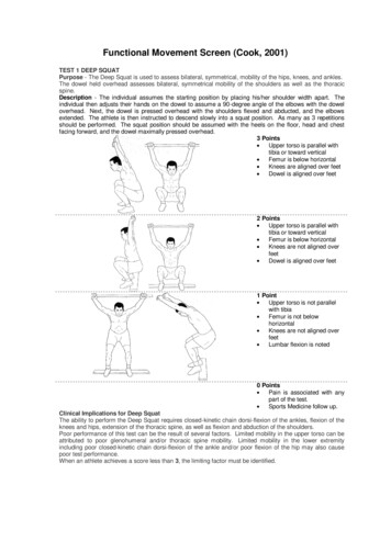
Fan BasicsFan TypesFans are described in three types and several sub-types.Axial Propeller Tube Axial Vane AxialMixed Flow Low Pressure High Pressure Extended PressureCentrifugal Airfoil Backward Inclined Radial Forward CurvedAxial FansAn axial fan discharges air parallel to the axis of theimpeller rotation.Propeller Fans Cost is generally low Blades attached to a relatively small hub Energy transfer is primarily in the form of velocity pressure Primarily for low pressure, high volume, non-ductedapplications1Cutaway View
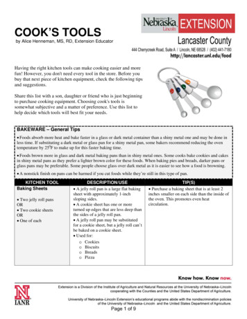
Fan BasicsTube Axial Fans More useful static pressure range than propeller fans Axial impeller in a tubular housing Blade cross-section either single thickness or airfoil Primarily for low to medium pressure applications suchas ducted HVAC applications where downstream airdistribution is not criticalCutaway View2
Fan BasicsVane Axial Fans Axial impeller in a tubular housing with straighteningvanes which improve pressure capabilities & efficiency Cost is generally high Generate medium-to-high pressure at good efficiencies Fixed or adjustable pitch blades Hub diameter is greater than 50% of impeller diameter Used for straight-through flow and compact installations Downstream air distribution is good Noise levels may be high Used for general HVAC in a wide range of pressureapplications Industrial applications include: drying ovens, paint spraybooths, and fume exhaust systemsCutaway View3
Fan BasicsMixed Flow FansA mixed flow fan is a hybrid ofan axial and a centrifugal fan, witha smaller backplate and angledblades. It discharges air parallelto the axis of the impeller rotation.As a general rule, it is moreefficient, smaller and quieter whenused in ducted, inline, supply andexhaust. Best selection for most inlineairflow applications Higher pressure abilitythan axial Lower sound levels thanequally sized centrifugalinline units Lower rpm than equal sizedinline units, for the same flowand pressure Does not require inlet bell oroutlet coneLow PressureHigh PressureCutaway ViewExtendedPressure4
Fan BasicsCentrifugal FansA centrifugal fan draws in air parallel to the axis of rotation anddischarges air perpendicular to the axis of rotation. The air thenfollows the shape of the fan housing to exit. In general, centrifugalfans are preferred for ducted or higher-pressure systems.Basic ComponentsHousingScrollHousingSide PanelShaftOutletCutoffImpellerSWSI Single WidthSingle InletLifting LugInletBearingSupport5DWDI Double WidthDouble Inlet
Fan BasicsCentrifugal fans are the ‘workhorse’ of the fan industry,operating in a wide variety of configurations, duties andenvironments. From light commercial, non-ducted applicationsto high pressure industrial and process ventilation, centrifugalfans can often be configured to meet the application demands.Examples are shown on these two pages.Centrifugal PowerRoof VentilatorCentrifugalKitchen ExhaustSquare InlineCentrifugal6
Fan BasicsAirfoil (AF) Fans Highest efficiency ofcentrifugal impeller designs 10-12 airfoil blades inclinedaway from the direction ofrotation Relatively deep bladesprovide for efficient expansion Primarily used in generalHVAC systems Industrial use in clean airapplicationsBackward Inclined (BI) Fans Efficiency slightly less than airfoil 10-12 single thickness blades inclinedaway from the direction of rotation Relatively deep bladesprovide for efficientexpansion within bladepassages Primarily used in generalHVAC systems Industrial applicationswhere airfoil blade isnot acceptable due to acorrosive and/or erosiveairstream7
Fan BasicsRadial Fans Less efficient than airfoil orbackward inclined fans High mechanical strength High speed at given dutyrelative to other designs 6-10 blades arrayed in aradial configuration Primarily used for materialhandling applications inindustrial environments Often specially coated to resistcorrosion or surface erosion Used in high pressureapplications not commonlyfound in HVAC systems.Forward Curved (FC) Fans Less efficient than airfoil orbackward inclined fans Low cost to manufacture Lightweight construction 24-64 shallow blades withblade heel and tip curved indirection of rotation Smallest wheel diameter forgiven duty of all centrifugalfans types Most efficient at low speeds Primary uses are low pressureHVAC applications such as residentialfurnaces and packaged air conditioningequipment8
Fan BasicsDrive Arrangements for Centrifugal FansSWSI: Single Width, Single InletDWDI: Double Width, Double InletArr. 1 SWSI: Belt drive ordirect drive. Impeller overhung. Two bearings on pedestal.Arr. 3 SWSI: Belt drive ordirect drive. One bearingon each side supported byfan housing.Arr. 4 SWSI: Direct drive.Impeller overhung on motorshaft. No bearings on fan.Motor mounted on pedestal.9Arr. 2 SWSI: Belt drive ordirect drive.Bearings on bracketsupported by fan housing.Arr. 3 DWDI: Sameconfiguration asArrangement 3 SWSIArr. 5 SWSI: Direct drive.Impeller overhung on motor.No bearings on fan. Motormounted to fan housing.
Fan BasicsRotation is viewedfrom drive sideArr. 7 SWSI: Direct drive,coupling connection.Arrangement 3 plus basefor motor.Arr. 7 DWDI: Direct drive,coupling connection.Arrangement 3 plus basefor motor.Arr. 8 SWSI: Direct drive,coupling connection.Arrangement 1 plusextended base for motor.Arr. 9 SWSI: Belt drive.Impeller overhung, twobearings, with motoroutside base.Arr. 10 SWSI: Belt drive.Impeller overhung, twobearings, with motorinside base.Adapted from ANSI/AMCA Standard 99-1010
Fan BasicsMotor Positions and Rotationfor Belt Drive Centrifugal FansTo determine fan rotation and motor location, face the fanfrom the drive side and identify the rotation as either clockwiseor counterclockwise and the motor position designated by theletters W, X, Y or Z as shown in the drawing below.Adapted from ANSI/AMCA Standard 99-1011
Fan Basics5 270 360 453190 Clockwise Fan Rotation 5 3122360 Shown5 180 Shown135 Inlet45InletCounter ClockwiseRoationCounterclockwiseFan Rotation270 180 5 135 90 22Position of inlet boxand air entry to inletbox is determinedfrom the drive side asdefined below:On single inletfans, the drive side isthe side opposite ofthe fan inlet.On double inletfans with a singledriver, the side withthe driver is consideredthe drive side.Position of inletbox is determinedin accordance withdiagrams. Angle ofair entry to box isreferred to the topvertical axis of fan indegrees as measuredin the direction offan rotation. Angle ofair entry to box maybe any intermediateangle as required.Positions 135 to225 in some casesmay interfere withfloor structure. Inlet BoxesAdapted from AMCA Standard 99-240512
Fan BasicsTop HorizontalRotation & Discharge DesignationsCentrifugal wiseCounterclockwiseClockwiseCounterclockwiseDown BlastTop Angular UpTop AngularDownClockwise13
Fan BasicsUp BlastRotation is viewedfrom drive mAngular UpBottom AngularDownBottomHorizontalClockwiseAdapted from ANSI/AMCA Standard 99-1014
Fan BasicsSpark Resistant ConstructionFan and damper applications may involve the handling ofpotentially explosive or flammable particles, fumes, or vapors.Such applications require careful consideration to insurethe safe handling of such gas streams. AMCA Standard 990401-10 deals only with the fan and/or damper unit installedin that system. The standard contains guidelines to be usedby the manufacturer and user to establish general methodsof construction. The exact method of construction and choiceof alloys is the responsibility of the manufacturer, however,the customer must accept both the type and design withfull recognition of the potential hazard and the degree ofprotection required.Type A All parts of the fan or damper in contact with the air or gasbeing handled and subject to impact by particles in theairstream shall be made of non-ferrous material. Ferrousshafts/axles and hardware exposed to the airstream shallbe covered by non-ferrous materials. Fans only: Steps must also be taken to assure that theimpeller, bearings, and shaft are adequately attachedand/or restrained to prevent a lateral or axial shift in thesecomponents. Dampers only: Construction shall ensure that linkages,bearings and blades are adequately attached or restrainedto prevent independent action. Ferrous containingbearings are acceptable if the bearings are located out ofthe airstream and shielded from particle impact.Type B Fans only: The fan shall have a non-ferrous impeller andnon-ferrous ring about the opening through which the shaftpasses. Ferrous hubs, shafts, and hardware are allowedprovided construction is such that a shift of impeller or shaftwill not permit two ferrous parts of the fan to rub or strike. Stepsmust also be taken to assure that the impeller, bearings, andshaft are adequately attached and/or restrained to prevent alateral or axial shift in these components.15
Fan Basics Dampers only: Construction shall ensure that linkages,bearings, and blades are adequately attached orrestrained to prevent independent action. Damper bladesshall be non-ferrous.Type C Fans only: The fan shall be so constructed that a shift ofthe impeller or shaft will not permit two ferrous parts of thefan to rub or strike. Dampers only: Construction shall ensure that linkages,bearings, and blades are adequately attached orrestrained to prevent independent action. Damper bladesshall be non-ferrous.Notes for AMCA Type A, B & C Construction:1. No bearings, drive components or electrical devicesshall be placed in the air or gas stream unless they areconstructed or enclosed in such a manner that failure ofthat component cannot ignite the surrounding gas stream.2. The user shall electrically ground all fan and/or damper parts.3. Non-ferrous material shall be any material with less than5% iron or any other material with demonstrated ability tobe spark resistant.4. The use of aluminum or aluminum alloys in the presenceof steel which has been allowed to rust requires specialconsideration. Research by the U.S. Bureau of Mines andothers has shown that aluminum impellers rubbing onrusty steel may cause high intensity sparking.5. All structural components within the airstream, includingnon-metallic materials, must be suitable for conductingstatic charge safely to ground, thus preventing buildup ofelectrical potential. Dampers with non-metallic bearingsmust include means by manufacturer of transferringelectrical charge from the blades to suitable ground.This Standard in no way implies a guarantee of safety forany level of spark resistance. “Spark resistant constructionalso does not protect against ignition of explosive gasescaused by catastrophic failure or from any airstream materialthat may be present in a system.”Adapted from AMCA Standard 99-401-8616
Fan BasicsBasic Terms Air Flow (Q): Amount of air moved per rate of time,typically measured in cubic feet of air per minute (CFM). Static Pressure (Ps): Resistance against airflow by thesystem (ductwork, fittings, dampers, filters, etc.). Typicallymeasured in inches of water gauge (in. wg.) For mostapplications Static Pressure along with CFM is used forfan selection. Total Pressure (Pt): The amount of pressure exerted byairflow on anything directly in the airstream. Velocity Pressure (Pv): Directly related to the velocityof the airflow at any given point in a system. Used tocalculate the airflow at any point in a system. Cannotbe measured directly and is calculated as the differencebetween Total Pressure and Static Pressure.Pv Pt - Ps Velocity (V): Speed of air in the direction of flow. Measuredin feet per minute (FPM). Power (HP): Rate of doing work, typically measured inHorsepower. For rotating machinery power is the amountof torque applied to a shaft to maintain a given rotatingspeed (RPM).HP RPM torque (ft-lb) / 5252.1 HP 33,000 foot-lbs per minute. Brake Horsepower (BHP): (as listed in a fan performancetable) The amount of HP required at the fan shaft tomove the specified volume of air against a given systemresistance. It does not include drive losses.17
Fan BasicsFan Selection CriteriaBefore selecting a fan, the following information is needed. Airflow required (CFM) Static pressure or system resistance (in. wg.) Air density or altitude and temperature Type of service Environment type Vapors / materials to be exhausted Operation temperature Space requirements (including service access) Fan type (see Fan Basics) Drive type (direct or belt) Allowable noise levels Number of fans System configuration Supply Exhaust Inline Recirculating Reversible Rotation Motor position Fan Class Expected fan life in yearsFan TestingFans are tested and performance certified under ideallaboratory conditions. When fan performance is measured infield conditions, the difference between the ideal laboratorycondition and the actual field installation must be considered.Consideration must also be given to fan inlet and dischargeconnections as they can dramatically affect fan performancein the field. If possible, readings must be taken in straightruns of ductwork in order to ensure validity. If this cannot beaccomplished, motor amperage and fan RPM should be usedalong with performance curves to estimate fan performance.Refer to Fan Installation Guidelines for more information.18
Fan BasicsFan Classes of OperationAMCA has defined classes of operation for various types ofcentrifugal fans and blowers. The class of operation is definedby a range of pressures and discharge velocities for a givenconfiguration and type of blower. A fan must be physicallycapable of operating satisfactorily over the entire class rangein order to be designated as meeting that fan class. Lowerclass numbers represent lower discharge velocities and staticpressures (See AF and BI SWSI example on next page).Although AMCA has defined the operating ranges of variousclasses, it does not prescribe how the fan manufacturermeets that requirement, leaving it up to the ingenuity of eachto design the product as they see fit. Higher class operatingranges will often require heavier duty components resultingin a higher cost.This is an important distinction. When specifying a fanclass, the designer is stating that a fan be capable of operatingover a specific range, and is not specifying a particular set offeatures or the physical construction of the fan.With the advent of modern selection programs, the fan classis determined at the time of selection. For more information,refer to AMCA Standard 99.19
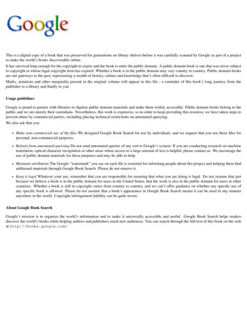
Fan BasicsOperating Limits Centrifugal AF and BI Fans - SWSI30(28 in wg @ 5440 fpm)25Ratings may bepublished in thisupper rangeFan must bephysically capableof performingover this rangeStatic Pressure (in wg)20(20 in wg @ 4600 fpm)Class VSelection Zone15(14 in wg @ 7580 fpm)(13.5 in wg @ 3780 fpm)Class IVSelection Zone10(10 in wg @ 6400 fpm)(8.5 in wg @ 3000 fpm)Class IIISelection Zone(6.8 in wg @ 5260 fpm)5(5 in wg @ 2300 fpm)(3 in wg
Engineering Cookbook A Handbook For The Mechanical Designer Third Edition This handy pocket reference is a token of LOREN COOK COMPANY’s appreciation to the many fine mechanical designers in our industry. It provides access to frequently needed information: Fan Basics System