Transcription
Radel Udel Veradel Acudel Radel PPSU, Udel PSU,Veradel PESU &Acudel modified PPSUProcessing GuideSPECIALTYPOLYMERS
2\ Sulfone Polymers Processing Guide
Table of ContentsIntroduction . . . . . . . . . . . . . . . . . . . . . . . . . . . . . 5Sulfone Polymers . . . . . . . . . . . . . . . . . . . . . . . . 5Part Ejection . . . . . . . . . . . . . . . . . . . . . . . . . . . . . . 14Draft . . . . . . . . . . . . . . . . . . . . . . . . . . . . . . . . . . . . . 14Ejector pins and/or stripper plates . . . . . . . . . . . . . . 14Udel Polysulfone (PPSU) . . . . . . . . . . . . . . . . . . . . 5 Injection Molding Equipment . . . . . . . . . . . . . . 15Veradel Polyethersulfone (PESU) . . . . . . . . . . . . . . 5Controls . . . . . . . . . . . . . . . . . . . . . . . . . . . . . . . . . 15Radel Polyphenylsulfone (PPSU) . . . . . . . . . . . . . . 5Clamp . . . . . . . . . . . . . . . . . . . . . . . . . . . . . . . . . . . 15Acudel modified PPSU . . . . . . . . . . . . . . . . . . . . . . 5Barrel Capacity . . . . . . . . . . . . . . . . . . . . . . . . . . . 15Resin Drying . . . . . . . . . . . . . . . . . . . . . . . . . . . . .6Press Maintenance . . . . . . . . . . . . . . . . . . . . . . . . 15 Screw Design . . . . . . . . . . . . . . . . . . . . . . . . . . . . . 15Rheology . . . . . . . . . . . . . . . . . . . . . . . . . . . . . . . 8Screw Tips and Check Valves . . . . . . . . . . . . . . . . 15Viscosity-Shear Rate . . . . . . . . . . . . . . . . . . . . . 8Nozzles . . . . . . . . . . . . . . . . . . . . . . . . . . . . . . . . . . 16Resin Flow Characteristics . . . . . . . . . . . . . . . . . . . 9Melt flow index . . . . . . . . . . . . . . . . . . . . . . . . . . . . . . 9Spiral flow . . . . . . . . . . . . . . . . . . . . . . . . . . . . . . . . . 9Molding Process . . . . . . . . . . . . . . . . . . . . . . . . . . 16Polymer Injection or Mold Filling . . . . . . . . . . . . . . 16Packing and Holding . . . . . . . . . . . . . . . . . . . . . . . 17Injection Molding . . . . . . . . . . . . . . . . . . . . . . . . 10Cooling . . . . . . . . . . . . . . . . . . . . . . . . . . . . . . . . . . 17Molds and Mold Design . . . . . . . . . . . . . . . . . . . 10Machine Settings . . . . . . . . . . . . . . . . . . . . . . . . 17Tool Steels . . . . . . . . . . . . . . . . . . . . . . . . . . . . . . . 10Barrel Temperatures . . . . . . . . . . . . . . . . . . . . . . . 17Mold Dimensions . . . . . . . . . . . . . . . . . . . . . . . . . . 10Mold Temperature . . . . . . . . . . . . . . . . . . . . . . . . . 18Mold Polishing . . . . . . . . . . . . . . . . . . . . . . . . . . . . 10Residence Time in the Barrel . . . . . . . . . . . . . . . . 18Mold Plating and Surface Treatments . . . . . . . . . 10Injection Rate . . . . . . . . . . . . . . . . . . . . . . . . . . . . . 18Tool Wear . . . . . . . . . . . . . . . . . . . . . . . . . . . . . . . . 10Back Pressure . . . . . . . . . . . . . . . . . . . . . . . . . . . . 18Mold Temperature Control . . . . . . . . . . . . . . . . . . 10Screw Speed . . . . . . . . . . . . . . . . . . . . . . . . . . . . . 18Mold Types . . . . . . . . . . . . . . . . . . . . . . . . . . . . . . .Two-plate molds . . . . . . . . . . . . . . . . . . . . . . . . . . . .Three-plate molds . . . . . . . . . . . . . . . . . . . . . . . . . .Hot runner molds . . . . . . . . . . . . . . . . . . . . . . . . . . .Shrinkage . . . . . . . . . . . . . . . . . . . . . . . . . . . . . . . . 1811111111Cavity Layout . . . . . . . . . . . . . . . . . . . . . . . . . . . . . 12Runner Systems . . . . . . . . . . . . . . . . . . . . . . . . . . . 12Gating . . . . . . . . . . . . . . . . . . . . . . . . . . . . . . . . . . .Sprue gating . . . . . . . . . . . . . . . . . . . . . . . . . . . . . . .Edge gates . . . . . . . . . . . . . . . . . . . . . . . . . . . . . . . .Diaphragm gates . . . . . . . . . . . . . . . . . . . . . . . . . . .Tunnel or submarine gates . . . . . . . . . . . . . . . . . . . .Pin gates . . . . . . . . . . . . . . . . . . . . . . . . . . . . . . . . .Gate location . . . . . . . . . . . . . . . . . . . . . . . . . . . . . .12121313131313Regrind . . . . . . . . . . . . . . . . . . . . . . . . . . . . . . . . 19 Measuring Residual Stress . . . . . . . . . . . . . . . . 19Extrusion . . . . . . . . . . . . . . . . . . . . . . . . . . . . . . 22Predrying . . . . . . . . . . . . . . . . . . . . . . . . . . . . . . 22Extrusion Temperatures . . . . . . . . . . . . . . . . . . 22Screw Design Recommendations . . . . . . . . . . . .22Venting . . . . . . . . . . . . . . . . . . . . . . . . . . . . . . . . . . 14Sulfone Polymers Processing Guide/3
Die Design . . . . . . . . . . . . . . . . . . . . . . . . . . . . . 22Extruded Product Types . . . . . . . . . . . . . . . . . . .Wire . . . . . . . . . . . . . . . . . . . . . . . . . . . . . . . . . . . . .Film . . . . . . . . . . . . . . . . . . . . . . . . . . . . . . . . . . . . .Sheet . . . . . . . . . . . . . . . . . . . . . . . . . . . . . . . . . . . .Piping and tubing . . . . . . . . . . . . . . . . . . . . . . . . . . .2323232323Start-Up, Shut-Down, and Purging . . . . . . . . . 24Start-Up Procedure . . . . . . . . . . . . . . . . . . . . . . . . 24Shut-Down Procedure . . . . . . . . . . . . . . . . . . . . . . 24Purging . . . . . . . . . . . . . . . . . . . . . . . . . . . . . . . . . . 24Thermoforming . . . . . . . . . . . . . . . . . . . . . . . . . 25Index . . . . . . . . . . . . . . . . . . . . . . . . . . . . . . . . . . 274\ Sulfone Polymers Processing Guide
IntroductionSulfone PolymersUdel Polysulfone (PPSU)Solvay offers the industry's broadest range of highperformance sulfone polymers. These high-temperatureamorphous thermoplastics are inherently transparentand are noted for their strength, rigidity, and outstandingdimensional stability. Continuous use in air or in steam atelevated temperature does not cloud, craze, or otherwisedestroy the material’s transparency.This tough, rigid, high-strength thermoplastic has a heatdeflection temperature of 174 C (345 F) and maintainsits properties over a wide temperature range. Udel PSUexcels in many fluid-handling applications and has over10 years of success replacing brass in pressurized hotwater plumbing applications.The natural color of sulfone resins is a transparent amber,ranging from light to medium. Solvay’s new producttechnology has significantly lowered the color of thesematerials, approaching water white for specific gradesof polysulfone. Sulfone polymers are also available inopaque colors and in mineral-filled and glass-reinforcedcompounds, which provide improved strength, stiffness,and thermal stability.This resin combines good chemical resistance with a highheat deflection temperature of 204 C (400 F), makingit a good fit for baby bottles and other food serviceapplications. Because the material is inherently flameretardant, it is also used for electronic components andtesting devices.Sulfone polymers can be processed following standardmethods for injection molding, extrusion, and blowmolding. Shapes can be machined for prototypeevaluations; film and sheet can be thermoformed onconventional equipment. Plus, you can do most postfabrication operations such as ultrasonic welding,adhesive bonding, and laser marking as well as heatstaking, threading, and machining. Sulfone polymerscan also be solution processed to make coatings andmembranes.For severe service applications requiring repeatedsterilization or uncompromising toughness, Radel PPSUreally stands out. With a high heat deflection temperatureof 207 C (405 F), it can withstand continuous exposure toheat and still absorb tremendous impact without crackingor breaking. It is inherently flame retardant and offersexceptional resistance to bases and other chemicals.Veradel Polyethersulfone (PESU)Radel Polyphenylsulfone (PPSU)Acudel modified PPSUThese proprietary blends open the door to more costsensitive applications that require toughness and chemicalresistance as well as hydrolytic and dimensional stability.Sulfone Polymers Processing Guide/5
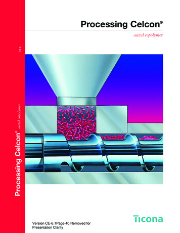
Resin DryingFigure 1: Drying Udel PSUMoisture content [ ppm ]Sulfone polymers will absorb moisture, and althoughthey are hydrolytically stable, they should be dried beforeprocessing. Processing wet resin will result in cosmeticdefects, such as surface streaks or splay marks oninjection molded parts and severe bubbling or streakingin extruded profiles. The moisture does not hydrolyzethe polymer or degrade its properties. Parts formed fromundried resin are only unsatisfactory in appearance, or insome cases weak due to formation of internal bubbles.Any unsatisfactory parts due to these cosmetic defectscan be reground, dried, and then remolded without lossof properties.1,000Recommended drying times and temperatures forVeradel PESU resins are: 3 hours at 177 C (350 F) 4 hours at 150 C (300 F)12345Drying time [ hours ]Figure 2: Drying Veradel PESUMoisture content [ ppm ] 4 hours at 135 C (275 F)Extrusion1000 2 hours at 163 C (325 F) 3 hours at 149 C (300 F)Injection molding500300200Sulfone polymer pellets can be dried in a circulating hot airoven or in a dehumidifying hopper dryer.Recommended drying times and temperatures forUdel PSU are:160 C ( 320 F )135 C ( 275 F )5,0003,0002,000177 C ( 350 F )149 C ( 300 F )5,0003,0002,0001,000Injection molding500300200Extrusion100 5 hours at 135 C (275 F).Drying below 135 C (275 F) is not recommendedbecause drying times would be excessive. The dryingconditions suggested represent minimums becausesulfone polymers cannot be over-dried. In fact, they canbe held at 135 C (275 F) for up to a week without harm.Drying curves for Udel PSU, Veradel PESU, and Radel PPSU are shown in Figures 1 through 3.6\ Sulfone Polymers Processing Guide012345Drying time [ hours ]Figure 3: Drying Radel PPSUMoisture content [ ppm ]The desired moisture content for injection molding isbelow 0.05 % (500 ppm) and for extrusion below 0.01 %(100 ppm). Hopper drying requires sufficient insulationand minimal system leakage. Inlet air temperature mustbe high enough to maintain a polymer pellet temperatureof at least 135 C (275 F), and the dew point of the inletair should be – 40 C (– 40 F). These conditions must besustained long enough for the polymer moisture contentto drop to below the minimum levels suggested for theprocessing technique to be used.177 C ( 350 F )149 C ( 300 F )5,0003,0002,0001,000Injection molding500300200Extrusion1000123Drying time [ hours ]45
Resin drying time may have to be increased in highlyhumid weather. An air-tight oven equipped with adehumidifying unit in which the air is recirculated over adrying bed is recommended as the most uniform andefficient drying method. Dried resin should be placed insealed containers to maintain dryness.In continuous molding and extrusion operations, it isrecommended that a dehumidifying hopper dryer beattached directly to the processing equipment. Theseefficient dryers permit continuous processing operations.The dryer should be sized such that residence time of theresin in the dryer is long enough to effectively dry the resinto the desired moisture content at maximum productionrate.Sulfone Polymers Processing Guide/7
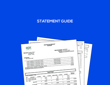
RheologyViscosity-Shear RateThe viscosity versus shear rate data are shown inFigures 4 through 6.Viscosity [ poise ]Figure 4: Udel P-1700340 C ( 644 F )360 C ( 680 F )380 C ( 716 F )400 C ( 752 F )15,00010,0005,0003,0002,0001,000100200500 1,000 2,0005,000 10,000Shear rate [ sec-1 ]Figure 5: Veradel A-301Viscosity [ poise ]50,00030,00020,00010,0008,0005,000340 C ( 644 F )360 C ( 680 F )380 C ( 716 F )400 C ( 752 F )3,0002,0001,00030100500 1,000Shear rate [ sec-1 ]8\ Sulfone Polymers Processing GuideFigure 6: Radel R-500050,00030,000Viscosity [ poise ]To assist the fabricator in the proper design of tools andprocessing equipment, the rheology of the Udel PSU,Veradel PESU and Radel PPSU resins has beenmeasured under a variety of conditions.3,00020,00010,0008,0005,000340 C ( 644 F )360 C ( 680 F )380 C ( 716 F )400 C ( 752 F )3,0002,0001,00030100500 1,000Shear rate [ sec-1 ]3,000
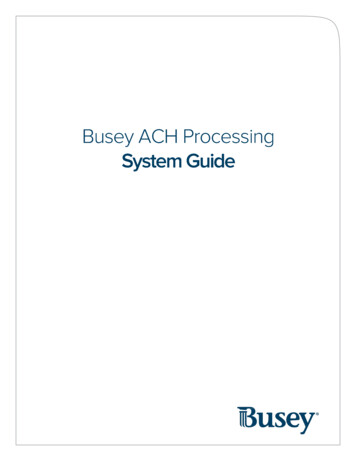
Figure 7: Spiral flow of Udel P-1700Resin Flow CharacteristicsMelt flow indexWall thickness [ mm ]GradeTemperature[ C]Typical MeltLoadFlow Rate[kg][g/10 min.]1.01.52.02.53.016Spiral flow [ inch ]Table 1: Melt flow rates of sulfone resins(ASTM D1238)0.540400 C ( 752 F )138 MPa ( 20 kpsi )14103 MPa ( 15 kpsi )1269 MPa ( 10 kpsi )35301025820615410250Udel PSU adel .080100120Figure 8: Spiral flow of Veradel A-301Wall thickness [ mm ]0.51.01.52.02.53.02560350 C ( 662 F )90 MPa ( 13 kpsi )152 MPa ( 22 kpsi )20390 C ( 734 F )90 MPa ( 13 kpsi )15152 MPa ( 22 kpsi )50403010205100020406080100120Wall thickness [ mils ]Spiral flowFigure 9: Spiral flow of Radel R-5000Wall thickness [ mm ]1.5352.02.53.03.5371 C ( 700 F )388 C ( 730 F )404 C ( 760 F )3080702560205015403010Spiral flow [ cm ]Spiral flow [ inch ]Another method of characterizing material flow isthe measurement of the flow length in a spiral cavityat various thicknesses, temperatures, and moldingpressures. Spiral flow data for Udel P-1700, Veradel A-301 and Radel R-5000 are shown in Figures 7through 9.60Wall thickness [ mils ]Spiral flow [ inch ]2.1640Spiral flow [ cm ]380020Veradel PESUA-201Spiral flow [ cm ]Another common method for quantifying melt flow isdetailed in the ASTM test method D1238, Melt Flow ratesof Thermoplastics by Extrusion Plastometer. The valuesobtained by this method must specify the temperatureand load used for the measurement. Table 1 gives thetypical flow rates for selected sulfone resin grades.205Injection pressure 138 MPa ( 20 kpsi )06080100120100140Wall thickness [ mils ]Sulfone Polymers Processing Guide/9
Injection MoldingMolds and Mold DesignMold PolishingIn general, mold design should be as simple as possible.Consideration should be given to part ejection as wellas gate location when determining cavity positioning.Thermal management of the mold is also critical. Thecirculating heat transfer medium should be designed tomaintain uniform cavity temperature. Failure to addressthese issues can result in part ejection problems.While an excellent surface appearance may not always berequired, it is necessary to remove all machining marksfrom the mold to ensure proper part ejection. All surfacesshould be polished in the direction of ejection. Texturedsurfaces are permitted for cosmetic parts; however,undercuts are not permitted.Tool SteelsPlating of tool steel is not generally required. If a highgloss, durable surface is required, it may be obtainedwith a surface treatment such as high-density chromeplating or titanium nitride treatment. Numerous other moldsurface coatings and/or treatments are commerciallyavailable. While we have not completely investigated allof them, we have not yet found any that offer a significantlong-term improvement over high-density chrome ortitanium nitride.As with any engineering resin, the number and quality ofparts that a tool is expected to produce will dictate thetool steel selection. For high-volume production, the initialexpense of high-quality tooling will be a sound investment.Generally, the common tool steels, such as H-13, S-7,and P-20 are acceptable for constructing injectionmolds. When molding glass- or mineral-reinforced resins,abrasion resistance is required and H-13 performs best.Soft metals, like aluminum, should be avoided evenfor prototyping. Tool steel should be hardened prior toproduction; however, it is wise to sample the mold beforehardening so that final dimensional cuts can be madeeasily.Mold DimensionsDetermine the general mold dimensions using theshrinkage value for the resin grade being considered(Table 2). For close tolerance parts, it is prudent to cut allmold dimensions “steel-safe”. That is, mold componentsthat will form internal features on the part (cores) shouldbe cut oversized and mold components that will formexternal features should be cut smaller than the expecteddimensions. After the initial material sampling, moldedparts can be measured and final mold dimensions can beadjusted to produce the desired part dimensions. The toolcan then be hardened.Table 2: Typical shrinkage values for selectsulfone polymersGrade0.6 – 0.7Udel GF-1200.4Veradel A-301 or 3300 Veradel AG-320 10Shrinkage [%]Udel P-1700 0.6 – 0.70.4Radel R-50000.6 – 0.7Acudel 220000.6 – 0.7\ Sulfone Polymers Processing GuideMold Plating and Surface TreatmentsTool WearWhile sulfone based resins are not chemically aggressivetoward tool steel, wear and abrasion can occur, especiallywith the glass and mineral filled grades. Typically, wearwill occur in high shear areas of the mold, such as gates,corners, and areas inside the cavity that are initiallycontacted by the injected resin. When designing the mold,wear should be considered when choosing gate locationand cavity layout. The use of gate inserts and easilyinterchangeable internal cavity components at expectedwear locations will minimize downtime for repairs.Mold Temperature ControlSince the process of thermoplastic injection moldingessentially consists of injecting molten resin into a cooledcavity and allowing it to solidify, then ejecting the moldedpart, it is very important that the temperature of the moldbe controlled properly. This is generally accomplished bycirculating a heat transfer medium through channels in themold. Sulfone polymers require mold temperatures greaterthan 138 C (280 F) so a heat transfer oil is required.Electric cartridge heaters should not be used. Althoughthey have the capability to heat the mold, they cannotremove heat from the mold. Since the polymer beinginjected into the mold is considerably hotter than thecavity, the excess heat needs to be removed. Thisis especially true in thermally isolated areas such ascore pins where heat may build up and cause ejectionproblems. Thermally conductive copper-beryllium pinsmay
methods for injection molding, extrusion, and blow molding . Shapes can be machined for prototype evaluations; film and sheet can be thermoformed on conventional equipment . Plus, you can do most post-fabrication operations such as ultrasonic welding, adhesive bonding, and laser ma