Transcription
wwwancalPartMtrilec.Ecuals.com Spectra Series Busway
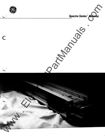
.comlPartManualswww.Electrica10ft., 1200 amp aluminum Spectra busway !':: : . ·.-,,.
.comualsctricalPartManGE Spectra SerieS"B All the muscle without the weight.GE engineers have broken the weight barrierwith Spectra Series busway. Its computer to 50%designed, all-aluminum housing is upile pru iding thelighter than other busway- wh(up to 5,000 amps)current-carrying capacitytion you've alwaysand short-circuit protecbusway.counted on from GETM(-· ·Less weight means big labor savings.r inotects yourrpnoitsulace WlthEpoxy inof experiensritsox yGE has appli d 25van ced epdab usway.oatings totra Seriescemater ial con lation r sun ineyiotoxtulapcinsecte )asClaeyears expops05(Ourfeliersed ?Yher loass tape uldvides toug ,ganCeoslor:mylar,ce it's prnesihtdnnaAhter'se d ao -.EJ t itur . art autom at fnufacpamreethhTheote- fquality.tin our stnedistliesnurapptects yoe o cororsupstaaethyou'rformance r equtpment .1'tyer:pehnnd y oubottoment-amstve \\) G of extras. . ottera 1·n\)\\sw' j w.C\ .ilecway is lighter thansbeseriS atrg.Since Specha dle nd h notterseasit',s or aother buswayallation umestnidanor)Iou ave on labost.al installed cttomtotooc k bvestm nt.ww.,most efficient busway systems available.Our exclusive adjustable joint connectorallows quick 112" busway length adjustment ibilityright in the field. This new level of flexected buildingmakes it easy to cope with unexpion .variations during installat ncludes ourSpectra Series busw y alsothatllev ll spnng washerspecially designed b s lts ongmal contact preretains over 90% ofe andmore secur , reliablsure . So you get a.nance-free Jomtwith avirtually m ainteunh e neoftny cagleOur new buswamploys JUSt a sme.atthrgeantion locatorsumque GE hand plug-posistsiasggs).uPldrot odn on lar ger plueev(pasnaationmal'.e ms all . ground is standard .ewousmgr . Choose nvoAnd 50% hfaruoye lnTip the scalom GEb usway fres·neSatrSpecPages ··r",,'frx\\\.'J ""L\.o·Quick Indexeaturesical Data8 Electrcal Data8 ph ysi8 Key Fa Plugs.logingonsu8 CataacflciSpemroFGuidea2-78-1112-2829-3031-3435
.comualsCABLE TAP BOXES*Table 18.1 Dimensions (inches)Numberof#2-600" C"MCMNo.CableLugsAluminum Copper BendofPerStacks Amp wH w H Space Phase1anDimensions, Cable BendingSpace and Lug Data225tricalPartMSpectra Series Tap boxes are used where a run ofbusway is fed by cable and conduit. Our corner postdesign permits removal of up to three side walls forcable access/entrance and for greater flexibility andinstallation ease. universal lug terminal plates willaccept almost all N E MA and non- N EMA mechanicaland compression lugs withoutfield modification.(Max P/s" wide).400600t BOX 18.1 EndTap Box·· Feeder or Plug-In.ElecBOTTOMA ND BOTHARE REMO SIDESVA BLELUGDIRE CTIO N(SEE BELOW)2500300040005000(1) Mechanic1717171717202020262617 262920 292920 2929-3317 2626-3317 2626292617 26262617 2620 2926 292934(CU·18181818344568188-2323230912.al Ty pe15-AL Wire)One GrouLugs Stannd Lug Stdardndarc d thr oughm p T ype OSta ndard3000-Amfor 4000- ptional.p .T omp AL, 5000Lug per PGround Lu-Amphase LuggsOpt"lonaI O ne.GroundCU.wwwer to company.153CU 2 Stan dard BoxDownpOS"IMPOR.on, SiitiTANT: Cde Viewer am. local/city codere .em e nl,152-Frg. 18·tdimIn theensesisiontus,antioumn b lugs furnishe qs% 'd, ulH1521839 34-15126 2933 343 3 3434150'[J pwrcOSitio ts an affect t.hen, etc. ,0(fi .if.ttngsfJ'10.18.3In vertedaDo fl ,P ros;, f/1/(Jnfl,
.comualsALTERNATE CABLE TAP BOXESTable 19.1 Dimensions (inches)Numberof#2-600"C "MCMNoCableLugsAluminum Copper BendofPerStacks Amp wLw L Space Pole1Dimensions, Cable BendingSpace and Lug Dataan. 7400L600LUGDIRECTION(SEE BELOW)1END AND BOTH SIDESARE REMOVABLE./·Fig. 19.1 Alternate End Tap Box: Feeder or Plug-Inwww.Electri280010001200262917 2617 2617 261515215217 2617 2620 291531518320 2920 2926 2918184518626 2918818833 3433 34232391239 342315--One Ground Lug Standard through 3000-Amp CU. Two Ground LugsStandard for 4000-Amp AL 5000-Amp. CU. Optional One Ground Lugper Phase Lug. 4:: P ::::5--LFig. 19.2 Standard Box Down Position, Side View4(1) Mechanical Type (CU-AL wire) Lugs Standard; Crimp Type OptionaLr,: ::::;::r-f----- c1Ca LUGBa- DIRECTIONAa1 ---C14----L ----Fig.19.31nverted Box Up Position, Side View19
.com12" "": '',,"' } j ", '' /!Spa aodJ;bJOatlNo.AluminumofStacks Amp wEL225LUG,,DIRECTION(SEE BELOW)1EL43/s2015CopperLugsPerPole143/s 202443/s 202443/s20152600 2443/s 202443/s 20152800 2443/s 202443/s 201531000 2443/s 202443/s 201531200 30628 306281841350 30628 306281841600 30628 306281852818632188-1882000362500-9-928 36-3632-99-3000 48 123/4 39 48 123/4 394000 48 123/4 39 48 123/4 392MCM242500 36Fig.20.1 Center Tap Box: Feeder or Plug-InwCableBendSpace400 24calPartM28"TOP, BOTTOM, AND BOTHSIDES ARE REMOVABLENumberof#2-600DimensiC.n ,Cehle.etlding'an tJOINT'ualsTable 20.1 Dimensions (inches)CENTER CABLE TAP BOXES5000---48123/4 46231923122315wwwFig.20.3 Standard Box Down Position, Side View2012500-2500 362Fig.20.21nverted Box Up Position, Side View.EDOWNtlec"0 SIDE"tri2000 Amp (Max) Center Branch Tap Boxes-9-3628-928186-1863000 43 123/4 28 43 123/4 281864000 43 123/4 28 43 123/4 281861865000---43-123/4 28(1) Mechanical T ype (CU-AL wire) Lugs Standard; Crimp T1; 1eOptional One Ground Lug Standard. Two Ground Lugs Sta: dard for4000-Amp AL, 5000-Amp CU. Optional OneGround Lug pe PhaseLug.
.comDimensions and Lug Data 1&BOX1No.ofStacksPOL ESTER GLASSBOTTOM PANELS FORFIELD CUT-OUT;;- -;;; ,I0---- ---1!"l -- 4 %REFIlT Y P REFtriFig.21.2 Standard Lug Phase160017172171717210002BOOFig.21.1 T hree-Phase End TapISIDE 452500265300040003333-5000-calPartM"' AYw an28" / ualsTable21.1 Dimensions (inches) T hree Phase End TapTRANSFORMER TAPS-3363339810(1) Mechanical Type (CU-AL wire) Lugs Standard; Crimp TypeOptional. One Ground Lug Standard.Two Ground Lugs Standard for4000-Amp AL, 5000-Amp CU.Optional One Ground Lug per PhaseLug.ElecTable21.2 Dimensions (inches) Single Phase Transformer TapsDimensions and Lug ber 232(1) Mechanical Type (CU-AL wire) Lugs Standard; Crimp TypeOptional. One Ground Lug Standard.Two Ground Lugs Standard for4000-Amp AL. 5000-Amp CU. Optional One Ground Lug per PhaseLug.POLYESTER GLASSBOTTOM PANELS FORFIELD CUT-OUTFig.21.3 Single-Phase Transformer Taps21
.comSWITCHBOARD/SWITCHGEAR STUB.tricalPartM.- .---00li 1.SIDE VIEWSpectra Series offers full factory coordination to otherGE equipment as shown. Other entrance combinationsare available. Refer to company. Straight and ElbowStubs are available with flange to joint or elbowdimensionS per Table 20.1. REFER TO GE PUB. GET-6937FOR SWITCHGEAR DATA.anProvides a universal stub for field connections. Availablewith or without Iugs. Accepts a II N EMA Iugs up to 17/s"wide. (See cable tap box data for lug type and quantity.)IIualsFLANGED END STUBIT4'12'saArJ1-3"- 1TYPG1- 2" ,0ca G -1'h''NMOTOR CONTROL CENTERlecT.469I1'/a"-214"III-0- -0 - j1-0--0--0II27/a"- 3'/a"4'/4''-41/2'I:II:1I-i::j;-j T -- \7.;\.EI1 62AMPS BAR BAR-Fig. 22.2w- LE J01-1 2.oo 1-1 2.oo L--1150 1 1 .5 1-I 1.W wwBARWIDTHS:225%"-6%''GE POWER BREAKSWITCHBOARDS CLASS 43, 5GE TYPE AKD-8SWITCHGEARFig.22.3Miq. --Table22.1 Stubs, Flanged EndsBAR HOLE PATTERN(1 STACK AND 2 STACK ARE SAME.)(All holes are .438 x .562 rectangles.)WI :1, 2,GE AV-LINE" CLASSSWITCHBOARDSFig. 22.1 Flanged End without Lugs BARBARWIDTHS:L0-i1III 2.00 8'/4''IQiftl8nsioll (Inches)*StraigM . . ise FlatStubs.·· 'Eiblw.ElbowsAL 225- 1140008613cu 11500010613*Add 1 inch to d1mensions shown forGE Type AKD-8 SwiL: :1ear
.comJP-i .,Tr - --- - - I'I i 1S41/2 :f Y P 1 OPENINGCUTOUTL -LIIItricalPartM12Fig.23.1I'I1anAualsFLANGED END (WITHOUT LUGS)* CUTOUT & DRILLING PATTERN- -j{!}H-I - - ""---j- -OPENINGCUTOUTFig. 23.2Table 23.1 Dimensions (inches)225-1200 AL225-1350 cu23.123.1.E1600-2000 AL2000-2500 /491h141/4411/1693/s141/15101h153/43000 cu23.2193/497/s93/s87/sw2500 ALAlecAMPS23.2271/4135/s131/s125/s3000-4000 ALww4000-5000 cu*Refer to Company for dimensions on Flanged Ends with Lugs.E51/4F-G101hHJ----21183/4261/423
.comPower Take-Off Device R600AanSpectra Series Flex-A-T ap joints accept boltedpower takeoff devices up to 1600 amps for manyapplications.The compact size and flexibility resulting from themodular design allow takeoffs to be mounted at anyJOint, whether feeder or plug-in. See Fig. 24.1ualsTable 24.2POWER TAKEOFFSOMRSODA & 1200ATable24.1Amp RatingDevice600-16001000-12001600Fig.24.1 Flex-A-Tap'M PTOFJ400AJJJKKM600A600-SOOAtricalPartMFusible SwitchesMolded Case Circuit BreakersCable Boxes225A600AJH. JL, J4V. JL4VK4V, KL4V. KM.KH,KLWITH OR WITHOUTGROUND FAULT1200A400ATB4 TRI-BREAK600ATB6 TAl-BREAKSODATBS TAl-BREAK150ATE & TB1"'H""W"93/ 151h151h151/7151h"D"63/471/4179! 1/J103/430443/4151h151/;151/;93/ 63693/H151/;1S1h1S1h1S1/;363/4493/4173/4Table 24.3 Meter Mod Ill WidthsAMPSAL 225-1600cu 225-2000AL 2000cu 2500AL 2500cu 3000AL 3000cu 4000cu 5000lec1J sidel - f'""' tJOINTI tJOINT2532 f Q.JOINT"H" 241/i'MIN38"MINPANELBOARDHEIGHT - 26" MINGROUPED METERINGSEE TABLE 24.3ww2073/ "MINw.E "8" DimensionFig. 24.2 Meter Mod Ill SectionFig.24.3 Flatwise PTCl Section Fig.24.4 Panel board Section
.comanEnd Boxes are used to terminate busway runs. No joint isrequired, and the end surface of the box is even with thejoint centerline. See Table 26.1 for "A" dimension. Box issecured via joint cap bolts.ualsEND BOXES/,.,//tricalPartM t JOINTFig.25.1WALL, CEILING AND FLOOR FLANGESwww.ElecFlanges are used to close wall openings when buswayruns pass through walls, ceilings and floors. See Table 26.1for "A" dimensions. Hole pattern aligns with spring riserbrackets. See Fig. 28.1.A 5W'END PLATESIDE PLATEEND PLATEFig.25.225
.comNO FUSE 2--anNo. of StacksualsTable26.1 "A" Dimensions (inches)-151823tricalPartMNote: Per NEC 364-11, a no-fuse reduced busway shall not exceed50 feet in length and have a current rating at least 1h the rating of theupstream overcurrent protective device.EXPANSION LENGTHS- THERMALEXPANSION 1"- BUILDING EXPANSION 2"Consideration should be given to the effects of thermalexpansion. The 1" expansion fittings may be necessaryfor long straight runs of 150 feet or more, particularly if thebusway is not free to move at the ends of the run. The useof the 2" expansion fitting is recommended when thebusway run crosses a building expansion joint.Fig.26.1 Reducerq; JOINTTable26.2 "W' Dimensions 1AmplecNo. of Stackswww226--24",/223/a""A"-2 11/a'' ( 2")2929335/sFig.26.2 Expansion Length
.comPHASEONLYNEUTRAL/GROUNDONLYGGAAc @ tricalPartMTOTALAualsA transposition length is available in any dimension fromthree feet through 10 feet. Standard lengths are 36" and4Z' "A" dimension varies with ampere rating. See Table26.1 for "A" dimension.anTRANSPOSITION LENGTHSNGNG(42" for 2000-4000 AL2500-5000 CU)Fig. 27.1 Transposition Length CNGABcBUSWAY FIELD CHECK PIECES/REPLACEMENT PIECESFig.27.2.ElecA Field Check Piece is a length of busway inserted into arun after the major portion of that run has been installed.This permits the release of straight lengths and portions ofthe run with known dimensions long before final dimen sions are set. Valuable time is saved by installing buswayearly in a construction project and using Field Check Piecesto complete the job. The 112-inch joint will provide evenfurther flexibility.To determine the length of piece(s) to be inserted,measure the opening length "L" as shown from the end ofeach housing and subtract 81/4 inches. This equals the bus way length "X" from center line of joint to joint and is theway to measure all Spectra Series busway pieces.JOINTS WITH 1/2-INCH 1\DJUSTABILITYNOMINAL POSITIONwwwEvery Spectra Series busway is supplied with the 112inch adjustable joint as standard. The modular joint pack ispreassembled to one end of each piece of busway andshipped in the "nominal" position. The joint caps have fourhousing mounting holes (eight on 5000 amp Copper) thatcontain twistouts permitting expansion or contraction ofthe joint up to 112 inch in either direction.JOINT (t TO JOINT X L -Sv.''Fig. 27.3 Joint Cap27
.comHANGERSualsVERTICAL MOUNTINGanSpring hangers are furnished to support the busway ateach floor. When the floor-to-floor span is over 16 feet,support for the spring hanger should be provided. Thequantity of springs supplied is based on busway weight.Simple adjustment procedures are included with installa tion instructions. Mounting holes align with floor flanges.Cat. No. (SBR 'X") where 'X" Quantity of springs 1, 2 or 3HORIZONTAL MOUNTINGtricalPartMFurnished one for every 10 feet. Designed for 1/z-inchdiameter drop rods.Fig.28.1Cat. No. SBR "X"SWAY BRACINGANCHOR POINTSWHEN REQ'D SWAY BRACINGANCHOR POINTSWHENREQ'D1\'iWHERE 'XX"16222833424515/s21/427/s lec BAR WIDTH33/s41/4411z576582 57/s611z81/4.E DROP RODwww,28"W"Fig. 28.4. One or two Stack Flatwise TrapezeCAT. NO.SBTESBT FSBT GSBT HSBT JSTACKS(1)(1)(2)(2)(2
GE Spectra SerieS"B All the muscle without the weight. GE engineers have broken the weight barrier with Spectra Series TM busway. Its computer designed, all-aluminum housing is up to 50% lighter than other bus way-while pru iding the (_ current-carryingcapacity (up to 5,000 amps) . , -·· and short-circuit protection you've alwa ys counted on from GE busway. Less weight means big labor .
