Transcription
ASCII Command ProtocolConfiguration andUser Manual99009150 G
ContentsGlossary of Terms3Information Symbols3Chapter 1. The BasicsChapter 4. Tips and Troubleshooting184.1 Troubleshooting184.2 Precautions1844.3 Before You Call Technical Support191.1 ACP Overview44.4 Talking to the Technician191.2 Determine the COM Port4Chapter 2. Reader Communication62.1 Communication with the Reader62.2 Help Command7Chapter 3. Commands22Appendix2383.1 Command Structure83.2 Perform a Function83.3 Assign a Variable93.4 Query a Variable93.5 Command Summary143.6 ACP Error Codes17 2015 RF IDeas Inc.IndexConfiguration User ManualPage 2
Glossary Of TermsTermsACPTelnetMinicomEIPPoEDefinitionsASCII Command ProtocolAn application protocol used on the Internet or local area networks to provide a bidirectional interactive text-oriented communication facility using avirtual terminal connection.A text-based modem control and terminal emulation program for Unix-likeoperating systemsEthernet Industrial ProtocolPower over EthernetInformation SymbolsSymbolMeaningNoteTipImportant 2015 RF IDeas Inc.DefinitionsNotes refer to useful information related to the text.Tips can provide hints and pointers in addition to the text.Important information can include prerequisites, limitations orcautions.Configuration User ManualPage 3
Chapter 1. The Basics1.1 ACP OverviewASCII Command Protocol (ACP) allows direct configuration of the device without downloading anapplication or creating a proprietary interface. This feature is available on CDC, Serial, PoE andEthernet based readers. The serial Prox reader communicates using ASCII commands. The readerthen parses the command, performs the operation, and displays the result or an error code. Allcommand strings begin with the prefix rfid: and end with a Return key (Enter), CR or LF.A remote serial connection must be made to communicate the commands to the device. Telnet istypically used in Windows. Minicom is typically available in all forms of Linux.There are other free communication programs that can also be used. RF IDeas does not endorse the use ofany particular utility. A few popular utilities like Terminal or Putty can be obtained if a Telnet session or otherutility is not provided with your operating system.1.2 Determine the COM PortWindowsUse device manager to verify the COM port selected for the device is available and installed correctly.CDC devices will install a virtual COM port over USB. Ethernet based models will install a LantronixCPR port. Take note of the COM port that the device is on.Using Telnet or another terminal application session, connect to the reader through the installedserial port located in device manager. If a Telnet or similar terminal program is not available, there aremany free utilities that can be downloaded from the internet.LinuxMost Linux distributions include an application called Minicom. Use Minicom or a similar terminalutility to communicate with the serial device. Be sure that the utility supports com ports higher thanthe typical 1 through 8.After the USB CDC device is enumerated on the Linux machine, a device of either /dev/ttyACM0or /dev/ttyACM1 can be found in the /dev/directory. Minicom users may have to create a symbolic linkfrom /dev/ttyACM0 to /dev/modem using the command ln -s /dev//tty/ACMO /dev/modem orln -s /dev/ ttyACM1 /dev/modem.Mac OS XThe /dev/cu.usbmodemfa211 device is found on a Mac OS X. Use a terminal utility to communicate 2015 RF IDeas Inc.Configuration User ManualPage 4
with the serial device. Be sure that the utility supports com ports higher than the typical 1 through 8.CommunicationSerial based readers communicate at 9600 baud, with no parity, 1 stop bit, and echo off. USB CDCreaders are virtual COM port and do not need the baud rate set.Ethernet and PoE based readers will communicate through a serial tunnel over the Ethernetconnection. The EIP PoE readers will require a Telnet type session to communicate to the reader andtypically will not require any special software settings. 2015 RF IDeas Inc.Configuration User ManualPage 5
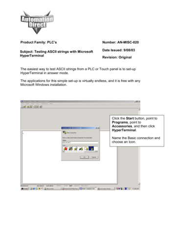
Chapter 2. Reader Communication2.1 Communication with the ReaderOpen a Terminal or Telnet session through a serial communications program.Be sure to set the data rate (baud) to 9600, Data bits to 8, Stop bits to 1, and Parity to None if using a programother than a Telnet session. Flow control is not needed as there is no software or hardware handshaking.Telnet connectionConnection to the reader can be accomplished directly through a Telnet session or other terminalbased application.Determine the IP address of the connected reader.From WindowsGo to Start Run and type CMD then press Enter to open a dos window(From Windows 7, Go to Start and type CMD in the search box and press Enter)At the command prompt, begin a Telnet session by typing the Telnet IP address, 10001, where theIP address is assigned to the PoE reader.Example: c:\ telnet 52.46.49.44 10001Once connected, press EnterA prompt will be displayed as shown:Image 1: Telnet window 2015 RF IDeas Inc.Configuration User ManualPage 6
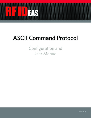
2.2 Help CommandHelp displays the commands followed by its data type and expected syntax. Type rfid:help andpress Enter.The Help command output displays as shown in the below left image:Image 2: Help CommandTo see what configuration settings the reader is currently set to, type RFID:VAR in the image above to theright. 2015 RF IDeas Inc.Configuration User ManualPage 7
Chapter 3. Commands3.1 Command StructureThe commands give users the ability to alter their data output to meet application needs and enhanceuser interaction. Use the commands to make the necessary changes to the reader configuration.Some commands have an immediate effect on the reader. However, most commands will require thatthey be stored to flash memory in order to become activated.Variables are set and viewed in RAM. With the exception of immediate commands, changes arelost when the reader loses power or the session is closed without sending the rfid:cfg.writecommand.Use rfid:var to display the list of current ram settings.The rfid:cfg.write function writes the RAM variables to flash memory.Once the variables are written to flash memory, they are non-volatile and are used by the reader.Commands are NOT case sensitive.Variables assigned to variables ARE case sensitive. All commands begin with a prefix string followed by one or more token strings with a perioddelimiter character between multiple tokens Functions must end with a CR or LF (From terminal or Telnet sessions; press enter or thereturn key) Variables can be assigned a value with an equal sign followed by the value or queried for itscurrent value with a question mark Any control characters other than CR, LF, and backspace terminate the command The Escape key cancels a commandCommand structure falls into one of three groups:1. Perform a function2. Assign a variable3. Query a variable3.2 Perform a FunctionA function performs an operation that may or may not display any results.A function may not be queried.For example, to write changes made to ACP variables into flash memory the function rfid:cfg.write CR would be used. 2015 RF IDeas Inc.Configuration User ManualPage 8
Certain functions that display a value or series of values display the string between curly braces foreasy parsing.For example, the rfid:qid function output 4}The general syntax is:PREFIX TOKEN { DELIMITER TOKEN } { { Value} {?} }The prefix string is rfid:3.3 Assign a VariableThere are three types of variables:1. Boolean2. Integer3. CharacterExamples of Boolean Assignmentsrfid:op.beep 0rfid:op.beep truerfid:op.beep Falserfid:op.beep FExamples of Integer Assignmentrfid:out.led 0003rfid:out.led 3All 16 bit integer values require a hexadecimal entryFor Example:pcProx Plus card types: rfid:cfg.card.type 0xFFFFExamples of Character Assignmentrfid:chr.fac ’:’ CRrfid:Chr.fac ’x3a’ CR3.4 Query a VariableA Variable can be queried to display its current value. 2015 RF IDeas Inc.Configuration User ManualPage 9
If a Variable is changed incorrectly, the settings can be replaced with those from flash using therfid:cfg.read command. The output of the Variable displays between curly bracesFor example:RF IDeas rfid:out.led?{3} Booleans display as true or false Integers display as 0.255 with leading zero suppression. 16 bit integers display in hex. Characters display as single quoted printable ASCII characters in the range 0x20.0x7E Values from 0x00 . 0x1F and 0x7F.0xFF will appear with a leading backslash lowercase x andthe two digit upper case hex number.Immediate CommandsThere are two commands which have an immediate effect on the reader’s end user experience.Those are rfid:beep.now and rfid:out.led.Changes to these Variables can be made in the end application to enhance the users experience withthe reader or alert them to a certain mode.For example, the LED can be toggled between color modes to provide a visual prompt for action orthe beeper can be sounded in a given pattern to provide an audible prompt to the user.Queued ID CommandsThe queued ID commands are a powerful group of commands that package the Identification datawith data statistics.They provide: A counter to reveal how long ago the data was read and whether it is still present at the reader Buffer overwrite statistics Lockout time revealing how long before another ID can be read ID in hex Bit count of the ID presented Card 000000}pcProxPlus: {0x1000,0,0x00,0;0x00} 2015 RF IDeas Inc.Configuration User ManualPage 10
Field Names{AGE, OVERRUN, LOCKOUT, BITCOUNT; ID}AGE: A hexadecimal age of the last card read in multiples of 48ms. Value stops incrementing when itreaches 0xFFFF indicating the ID has not been present in over 52 minutes. The value resets when anew credential is presented to the reader.The rfid:qid.id or rfid:qid.id.hold functions can be used to clear the age counter. Asshown in the Format examples on the previous page, the card was read 4,096 (0x1000 hex) x .048 196.608 seconds ago or 3 minutes and 16 seconds.The Age value also functions as a means of detecting card presence.See the following sections on “Queued ID on pcProx readers” or “Queued ID on pcProx Plus line of readers” formore information.OVERRUN: A counter indicating the number of times the buffer has been over written with new datawithout the content being read. Value range: 0 through 255LOCKOUT: Time (in multiples of 48ms) remaining until another ID can be read. The rfid:qid.id.hold function can be used to clear the lockout field, allowing a new card to be read immediatelyafter clearing the lockout time.BITCOUNT: The bit length of card data (26 to 255). The rfid:qid.id or rfid:qid.id.holdfunctions can be used to clear the bit count field along with other associated fields in the datapackage. Queued ID Commands (cont.--)ID: Card data in hexadecimal. The value will update, provided that the lockout time has expired andnew data has been read. The rfid:qid.id or rfid:qid.id.hold functions can be used to clearthe ID field.Queued ID on pcProx ReadersWhen first powered on, all values will be set to zero. The ID data is framed to 10 bytes and padded toprovide a set ID field limited to 80 bits in length.With a credential still present in RF Field, the Card Age field will increment to a low value number andreset as the data is updated from the RF data transmission. This provides a means to detect cardpresence.When the card is removed from the RF field, the data transmission is no longer updated. The IDdata will be retained in the queued ID data package and the Card Age will increment to 0xFFFF(approximately 52 minutes) unless a new credential is presented to the reader.The queued ID data package can then be cleared, if desired, using rfid:qid.id or rfid:qid.id.hold commands. 2015 RF IDeas Inc.Configuration User ManualPage 11
See the Command Summary list on page 14 for more information.pcProx Output ExamplesReader first initialized and no card presented (powered on):{0x0000,0,0x00,00;0x00000000000000000000}After card read (as shown with leading and trailing parity }rfid:qid.id sent to the reader:{0x0002,0,0x05,24;0x00000000000000CE0004} Data collected{0x0000,0,0x04,00;0x00000000000000000000} then cleared.Make note of the lockout time remaining.Queued ID on pcProx Plus ReadersThe pcProx Plus introduced the ability for an ID to be any length up to 256 bits. The queued IDpackage fields remain consistent with the pcProx readers. The ID data is no longer framed to 10bytes and the Card Age field has been enhanced to give a faster indication of card presence.When a pcProx Plus reader is first powered on, the Card Age will be set to 0xFFFF and all othervalues will be set to zero. With a credential still present in RF Field, the Card Age field will remain at0x0000 until the RF data transmission has ended, indicating the card is no longer present.When the card has left the RF field, the Card ID will remain and the Card Age counter will incrementto 0xFFFF unless a new credential is presented, repeating the process again.The queued ID data package can then be cleared, if desired, using rfid:qid.id or rfid:qid.id.hold commands.See the Command Summary list on page 14 for more information.pcProx Plus Output ExamplesReader first initialized and no card presented (powered on):{0xFFFF,0,0x00,0;0x00}After card read (as shown with leading and trailing parity stripped) card still present:{0x0000,0,0x05,24;0xBE0004} 2015 RF IDeas Inc.Configuration User ManualPage 12
After card removed (as shown with leading and trailing parity stripped):{0x0051,0,0x05,24;0xBE0004}rfid:qid.id sent to the reader:{0x0002,0,0x05,24;0xCE0004} Data collected{0x0000,0,0x04,00;0x00} then cleared.Make note of the lockout time remaining. 2015 RF IDeas Inc.Configuration User ManualPage 13
3.5 Command SummaryCommandrfid:beep.nowData TypeR, W, R/WDefinitionINTWSounds the beeper immediately up to 5 short beepsor 2 long :cfg.card.listFunctionrfid:cfg.card.typeINT (hex)R/Wbeep.now variables:1 – single short beep2 – two short beeps3 – three short beeps4 – four short beeps5 – five short beeps101 – single long beep102 – two long beepsVerify or switch the current configuration set inRAM (Config 1 or 2) Some readers have multipleconfigurations. Each configuration has settingsassociated with the designated card type setting.Enable priority card read. IF true, currentconfiguration is given priority over the alternateconfigurationView list of supported card types and theirhexadecimal entries for the rfid:card.typecommand.Verify or set card type for current configuration inRAM as 16 bit INT (0x0000.0xFFFF)Make note that 0x0000 is R/Wrfid:chr.3CHARR/Wrfid:chr.count.lead INTrfid:chr.count.trail INTCHARrfid:chr.eolR/WR/WR/Wrfid:chr.facR/WCHAR 2015 RF IDeas Inc.Read the flash memory settings in to RAMReset the flash memory to the factory defaults.Write the variables from RAM in to flash memory.1st card data delimiter character( A - Z, 0 - 9, a - z or ASCII \0x00 .\0x0D)2nd card data delimiter character( A - Z, 0 - 9, a - z or ASCII \0x00 .\0x0D)3rd card data delimiter character( A - Z, 0 - 9, a - z or ASCII \0x00 .\0x0D)Verify or set the leading character count (0 to 3)Verify or set the trailing character count (0 to 3)Verify or set end of line termination character( A - Z, 0 - 9, a - z or ASCII \0x00 .\0x0D)Verify or set separating character between thefacility code and ID data ( A - Z, 0 - 9, a - z or ASCII\0x00 .\0x0D) Ex: 123 ; 456789Configuration User ManualPage 14
CommandData TypeR, W, .luidBOOLINT /W1st character sent when card is removed( A - Z, 0 - 9, a - z or ASCII \0x00 .\0x0D)2nd character sent when card is removed ( A - Z, 0- 9, a - z or ASCII \0x00 .\0x0D)IF True, enable echo of user input and use ofbackspace keyIF True, enable RF IDeas command promptVerify or set the logical unique identifier as 16 bitINT (0x0000.0xFFFF)Read the device part numberRead firmware version (major . minor . variant)IF True, use 64 bit math on ID dataIF True, use 64 bit math on facility code dataVerify or set Length of facility code output(up to 25 digits)IF True, enable facility code output as hexEnable output of facility codeSet to True to separate ID and FAC. Falseprocesses ID and FAC together.IF True, hex ID data is output in lowercaseVerify or set ID data length (0 to 25 digits). Ifvalue is shorter than actual Id length the left mostsignificant digits will be truncatedThe Help Command screen shot shows thevalue range of 0-255, since internally this isstored as a WIF True, enable ID data output as hexView menu of commands, summary of output typesand variable optionsBeeper output control True beep, False silentContinuous read mode True continuousoutput, False single output of credential dataIF True, enable Quiet mode. (IE: Credential data isnot displayed)Data can still be retrieved using functionrfid:qidrfid:out.ledBOOL 2015 RF IDeas Inc.R/WLED output control 0 off, 1 red, 2 green,3 Amber (Immediate out w\o write)255 Automatic control by reader (requires write toflash) red on standby, green whencredential is readConfiguration User ManualPage 15
Commandrfid:qidData TypeR, W, R/WFunctionDefinitionReads current queued ID dataEXAMPLE Output ---Note the use of commas and semicolons-FORMAT of Output String:{AGE,OVERRUN,LOCKOUT,BITCOUNT;ID}AGE (New: Age (in hex) of last card read as amultiple of 48ms. Value stops at 0xFFFF. Use qid.id function to clear the age counter. As shown: thecard was read 4,096 (0x1000 hex) x .048 196.608seconds ago or 3 minutes and 16 seconds.OVERRUN counter (Values: 0 through 255):number of times buffer has been over written withnew data without content transfer.LOCKOUT: Time (in multiples of 48ms)remaining until another card can be read.BIT COUNT bit length of card data (26 to 255). Asshown: The ID contains 80 bits.ID: Card data in hexadecimal. As shown: Card is 80bits and is onRead the card data and reset lockout timer. Oncethe function is called, a new card can be readimmediately after without waiting for the lock outtime period to expire.Reads the card data, clears the age, overrun, andbit count after function is called.Combined functions of rfid:qid.hold and rfid:qid.idVerify or set current data hold time setting inmultiples of 48ms. (0 - 200) Also controls durationof Green LED during Auto mode.Outputs current command variables in ram (Similarto a .HWG file). Output can be captured, edited andwritten back into the device.To prevent an input buffer overflow, delay eachcharacter by several TR/Wrfid:wieg.rev.bitsBOOLR/W 2015 RF IDeas Inc.Verify or set card data output bit count (0- 255)IF True, Invert card data output bits (1 to 0, 0 to 1)IF True, use wiegand qualifier to verify card bitcountWiegand Qualifier: Number of bits (0 - 255) carddata must have to be acknowledged as a readIF True, reverse bits of credential output lsb to msbConfiguration User ManualPage 16 page
Terms Definitions ACP ASCII Command Protocol Telnet An application protocol used on the Internet or local area networks to pro- vide a bidirectional interactive text-oriented communication facility using a virtual terminal connection. Minicom A text-based modem control and terminal