Transcription
.,.w "". SLOT MACHINESTheCompleteServiceManualFor(SERIES E 1980-1986 )' 19.95Marshall Fey
(]S SLOTThe Complete Service Manual For Series E 1980-1986Marshall FeyTable of ContentsGetting Acquainted . 2Introduction to the Bally Electronic Slot . 3Built-In Test Functions . 5Initial Set-Up (Maintenance Tests)Step 1: "Start of New Game" . 6Step 2: Load (Output) Test . 7Step 3: Switch Test . 10Step 4: Hopper Test . 12Step 5: Reel Reader Test . 13Step 6: Memory Check . 14Step 7: Maintenance Meter Display Test 15Step 8: Game Functional Test . . . 176-Diget Led Display. 814 Diget Double Progressive Display. 9Normal Operation . 18Bookkeeping Meters . 19Game Condition Malfunction Codes . 20Standard Options . 23Game Condition Malfunction Chart . 26Miscellaneous Features . 27Service & Adjustments . 28Reel Mechanism Adjustments . 28Reel Reader Assembly Adjustment . 32Hopper Payout Service & Adjustment. . 33Handle Mechanism Service . . 35Molex Plug Service . 36State Laws for Possession of SERIES E . 36Lubrication of Handle Mechanism . 37Lubrication of Reel Mechanism . 38Cabinet Assembly. . . . 40Front Door Assembly . 42Reel Mechanism Assembly. 44Reel Mechanism Boards . 46Hopper Control Boards . 47Hopper Payout Unit Assembly . 48Handle Mechanism Assembly . 49Game Power Distribution Schematic . 50P.C. Board Power Distribution Schematic. 51I/O Board J-1 Schematic . 52I/OBoard J2 & J3 Schematic. . . . . 53I/O Board Assembly. 54Sound Board Assembly . 55MPU Board Assembly. 56Power Supply Board . 58Delay Relay Board . . 59Slot Stimulator Test Station . 59Cabinet Cable Connections . . . 60Triacs . 61Description of Boards . . . 61Game Transformers . 62Input/Output Voltage Schematic. . 62Trouble Shooting . 63Dealers (Parts & Repairs) . 63Other Informative Liberty Belle Books. 64Published byLiberty Belle Books2925 West Moana LaneReno. 89509·6011First Edition 1995ISBN No. 0-9623852-3-9Library of CongressCatalog Card No. 95-75025 1995A portion of the contents of this book was reproduced from six Bally SERIES E Manuals. The use of thismaterial was granted through the generosity of Mr. Hans Kloss, President & COO, Bally Gaming, Inc., in acontract dated December 17. 1994. This subject matter remains the property of Bally Gaming International. Inc.All the revisions and new material are the property of Liberty Belle Books.No part of this book may be reproduced without written permission, except in critical articles and reviews.Special appreciation for numerous contributions are extended especially to Tim Becke. Bally Gaming. Inc.;and to Betty Mann. Bally Gaming. Inc.; and to John Riggs. Jr. Digitronics.Liberty Belle Books makes no representation or warranty with respect to the procedures contained in thispublication or the results to be achieved in following such instruction procedures.
GETTING ACQUAINTEDIn 1980, after sixteen years of manufacturing Electro-Mechanical slots. Bally. withapproximately 90% of the domestic market. introduced the SERIES E- I 000. Thissecond generation of machines, a continuation of the earlier models, featured solidstate electronic circuitry that replaced the ageing electro-mechanical components.These microprocessor driven slots were popular with the casinos offering betterdependability and security. Three years later, a new revamped line, dubbed theSERIES E-2000, were brightened-up with new artwork, the replacement of the dull6-8 volt lights in the top sign by a fluorescent lamp and sound enhancements. Bothseries used essentially the same case, high capacity hopper and mechanism as theElectro-Mechanicals. The operation and maintenance of these components are thesame as their predecessors and are very dependable requiring a minimum amount ofservicing. Many operating functions ot the SERIES 2000, including reading the reeldisks, totalizing the coins played and controlling the coins payed from the hopper,are electronically controlled.The First 10-WayAdditional advantagesof the SERIES E werea simple alteration ofthe payout percentagebychangingthePersonality Prom andthe capability of morecomplex pays. Capitalizing on this latterfeature, the Model 1212was one of the firstmodels introduced inthe new line. It was a 5line game that paid leftto right, making it thefirst slot to pay 10different ways. Proud ofthis accomplishment,Bally featured theModel 1212 in a fullpage color ad thatappeared in an 1980issue of the NevadaMagazine,TUTORIALGetting Acquainted by Performingthe Eight Maintenance TestsTo gain a basic understanding of the electronic functionsand LED displays, it is advisable to read the introductorypages, 3,4 & 5 before beginning the series of tests thatbegin on page 6 and end on page (I8). Aiding in troubleshooting, pages 20-23 explain the malfunction codes and page26 has a chart of the malfunction codes that are displayed in theLED display.2
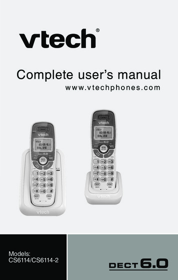
INTRODUCTION TO THE BALLY ELECTRONIC SLOTThis manual describes the operation of BALLY'S ELECTRONIC SLOTMACHINE. You will find, in comparing this machine with theelectromechanical version, that the same basic functions andtiming relationships exist*. In fact, the only visible difference to the player is the addition of a 6 digit LED (LightEmitting Diode)display**. This display, in addition to providing the function of InN METER, also performs several otheruseful functions.For example, a slot machine attendant,called to the machine by a player, will be able to determineby observing the code on the LED display, whether the machinehas detected a problem in its operation.If there is aproblem, the code will tell the attendant if it is a coin jam,empty hopper, or something more serious, requiring a technicianThe code displayed will also help the technician localize theproblem. The LED display also permits the reading of meterswithout entering the machine.For the sake of discussion, when referring to examples of theLED display, this manual describes the digit positions withinthe display as columns 1 thru 6, from left to right.2:34562:3456[ [QTIE[Examples of what might be observed in the LEDdisplays of the Series 1000 (small round windows) andthe Series 2000 (larger rectangular windows) . Theoperation of the test procedures are very similar inboth series. When preforming a test on the Series 1000use the same codes displayed as used on the Series2000, except in cases where variations are noted bythe addition of the small round window LED displays.Bally has taken advantage of the advanced technology of integrated circuits (IC's) to incorporate into the machinereliability, flexibility, as well as bookkeeping, security,and maintenance features which would have been impractical,if not impossible, a few years ago. A microprocessor-basedsystem was determined to be the most effective approach toachieve these desirable objectives. The MICROPROCESSOR (CPU)is an IC that performs the functions of the central processingunit of a computer. Thus, it controls the interpretation andexecution of instructions. These electrically coded instructions, called a PROGRA11, are stored in other IC's, calledMEMORY CHIPS. The CPU receives information in the form ofINPUTS, which tell the CPU the status of SNITCHES, REELS, ETC.This enables the CPU to determine which OUTPUTS (coilS, lamps,motors) should be on or off for the particular MODE of operation that the machine is in.(ACCEPTING COINS, READING REELS,DIS"ENSING COINS, DISPLAYING METERS, SELF-TESTING, ETC.)The CPU, MEHORY CHIPS, and other CONTROL LOGIC are located ona MICROPROCESSOR UNIT (MPU) BOARD.***See Reel Spin Time Variations on Page 24.An exception to this is a model which contains a ReplayRegister (Credi t leter) or Progressive ,Tac}:not Meter.3
WHAT TO EXPECT WHEN POWER IS APPLIEDWhen power is applied, a brief self-test of vital functionsof the MPU board will-occur. During this self-test coins arelocked out.After completion of this self-test, the slotmachine will return to some point in its normal operation.This point is determined by what the machine was doing ,.;henpower was turned off.THE CENT:::R T'NO DECIMAL POINTS INDICATEA RESET (PON'ER OFF, STATIC DISCHARGE, ETC.) OCCURRED SINCE THELAST HANDLE PULL.The 6-DIGIT LED DISPLAY may appear as any of the 3 followingexamples when power is turned on.If the display exhibitsa severe flicker or takes a form other than those mentionedbelow, see BUILT-IN TEST FUNCTIONS paragraph on following page.1.Machine was at some point in its normal operating sequencewhen power was removed.Example:The number in the second column,in this example 1, indicates onecoin was put into machine forprevious game and the 005 in thefourth, fifth and sixth columnsindicates number of coins paidout. (In this case 5 coins).Example:In this example 6 coins had beenplayed; 1000 coins had been paidout.fL[Jrnrnrnll[ EI. 2.The processor had detected a game malfunction prior topOIver being removed.NOTE:Examples of malfunction codes in this text arethose which correspond to the Bally Slot codes. Onsome models, different codes are used. A cross referencechart is provided for your convenience (page 28).Example:GTllrnrnfCl'sl U!:::L l 3.The 31 in the first two columnsin this example indicate a particular malfunction. (In thiscase a hopper jam.) The digitsin the last three columns indicate the number of coins paidout before malfunction occurred.The machine was in self-test #2 mode "hen power ,,,as turnedoff.Example: [gIB.IB.@4If 8's are present in all sixcolumns for about one second,the machine \d 11 energi ze eachlamp, coil and motor in a sequencedetermined bv the features ofthat particular machine.[SEE TEST '2 IN SECTION III)
If Personality PROM (r17) is not installed in the MPUBoard, the following sequence will be observed on the display when pm,er is applied:fLl,f-. [[[t ,*Ib Is.ILl/.:1.I r IL:. , IIIL!.:J-I/-/ICJICJ CJICJ[/:JI'-1. LI. U. U. U. 1.:1.briefly, thenfor 1 second, thenfor 1 second, repeat.(See "CAUTION" on Page 7)*Irrelevant Data for AS-2978-5, 6 or 7; Blank for AS-2978-3.BUILT-IN TEST FUNCTIONSThe BALLY ELECTRONIC SLOT MACHINE is equipped with two typesof test functions.First, a diagnostic self-test on POWER UP. This test isprimarily used to localize a problem in the MPU BOARD.These particular problems are discussed in detail in"MPU BOARD TEST STATION OPERATORS GUIDE AND TEST PROCEDURES":FO-650-l for MPU Board #AS-2978-3FO-650-3 for MPU Board #AS-2978-5 or -6FO-650-11 for MPU Board #AS-2978-7Second, manual tests. All manual tests are initiated by uSingthe TEST button on the hopper control board. The number oftimes the TEST button is pressed determines which test will beperformed. The tests are numbered as follows:1.2.3.4.5.6.7.8.NOTE:START OF NEW GAMECOIL AND LAMP (LOAD) TEST(See "CAUTION" on Page 7)SWITCH TESTHOPPER TESTREEL READER TESTPROGRAM TESTMETER DISPLAY TESTGAME FUNCTIONAL TESTThe Door Slvitch must be open to enter any manual test.Closing the door while in TEST MODE, (decimal points in display) terminates the test in progress, indexes the reels andcauses the display to read:ClOSing the door has noeffect if M7 is removed.On the Series 1000, closing the door while in theTEST MODE (decimal points in display) showsthis display,5
INITIAL SET-UP (MAINTENANCE TESTS)Performing the following procedure will assure the operatorthat the machine is operating properly before putting i tout on location. If any problem is encountered while testing the machine, the entire procedure should be repeated.This will assure the operator that some previously testedpart has not been affected while correcting another problem."STARTStep 1.ofNEW GAME"vii th the door open, turn the power swi tch ON.Near the front of the HOPPER unit is a printedcircuit board with two push button switches located at the top. These switches are labeledRESET (left) and TEST (right). Press the TESTbutton ONE Tll1E ONLY, while observing the digitaldisnla v [[[ff[]*ForFornotwas",hile button is depressedMPU Board AS-2978-3, these digits are blank.MPU Boards AS-2879-5, 6 & 7, these digits dochange from what was showing before the buttondepressed.r--l[g[Q[]O.nnnnU. U. U. '-I.II. or approximately one secondafter button is released, then. . . enainsuntil some action ista::en such as closing door and laying machine, pressing TESTbutton, pressing RESET button, etc.The DOOR OPEN lamp (in tower)switch is open. COIN LOCKOUTmachine is in any test mode.is lit whenever power is on.any self-test terminates it.HOT TIP6(!!!!!!!H is lit whenever dooris in effect while theGeneral illuminationClOSing door while intest continuesThe wafer connectors on the boards aredesignated as "J" connections. A blackenedarea on a wafer, usually indicates a bad ordirty connection. This problem can beremedied by cleaning the offending point.
Step 2.LOAD TESTPress TEST button two times.CAUTION: DO NOT perform this test withoutpersonality PROM (1-17) installed, as thiswould cause the hopper fuse to blow.In this test, one OUTPUT(or LOADJis energizedeach second. Closing the coin switch while inthis test causes the CPU to stop sequencing,continuously energizing the LOAD that was activewhen the switch was closed.fnTrirnrnrnGWhile button is depressed(Zeroes are blank on AS-2978-3), .I\" IU.n U.I I 1-1.I I IU.I I l.:rFor approximately one secondafter button is released, then t: B-I.1. (LED TEST)Lit along with reel reader lampsfor approximately one second,then . . Example'2. (TILT lamp test)Lit along with TILT lamp forone second, then . Example:3. (DEPOSIT COIN lamp test)Lit along with DEPOSIT COIN lampfor one second, then continuesin this manner energizing eachlamp and coil (except hopper motorand displaying associated code.test continuesTEST SWITCHLocated on the Hopper Board, the push button TEST SWITCH,in conjunction with the LED display, is used to perform theMaintenance Tests described on pages 6-17. The six digit LEDdisplay is mounted on the front door at the right of the reelwindow.RESET SWITCHThe game Reset Switch is located on the Hopper Board at thetop right hand corner. Pushing this reset button often restartsthe machine after there has been a minor malfunction.7
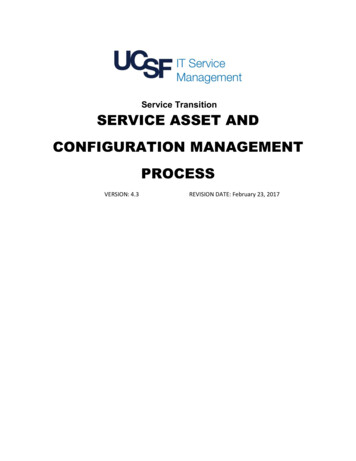
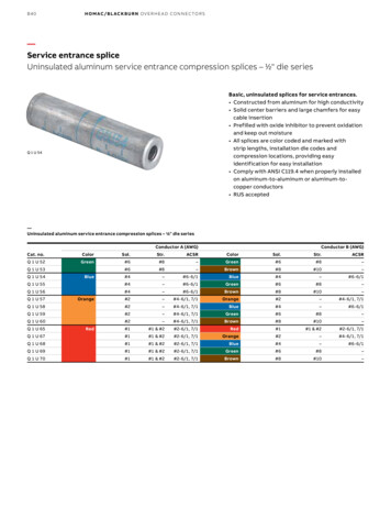
At the end of each test cycle, the contents of the "LOADTEST lclETER" indicating the number of times this test hasbeen performed are displayed. The meter reading is displayedfor approxinately three Seconds in the following format:inrnrn luTLiillExample- 1'::!.: L2:L': This meter is incremented at the beginning of the test cycleand is not resettable.After all loads have been tested, the CPU beginsagain at step 1 (LED test), continuing until test isterminated by either pressing the TEST button or closingthe noor.Turning off power or pressing the RESET buttonwhile in this test causes the CPU to return to step 1(LED test) and continue from that point. After thefirst step, the CPU is programmed to display a code aseach output load i3 energized. This code is used bythe technician to determine which circuit the CPU isacti vatinrr IExample:and ta:t::est v .f nr", \2[[ B[ [gJThe 2 in the first column shOt;s thi't the game is in test mode#2. The 1 in the third column shows that the CPU is addressingIO Board #1 (standard IO for all games). The 4 in the fourthcolumn sholtIS that the CPU is addressing OUTPUT PORT #4.The 20 in L e fifth and sixth columns shows that the CPU isactivating the sixth circuit of the PORT.(PORT is definedto be a device which ;:: rovides electrical access to a systemor circuit. This system uses PORTS with six circuits orBITS, coded 01, 02, 04, 08, 10 and 20.)test continuesUJUlU3U,U5U6[iJ--' [5J' I. I. '. '-'1111111/1111--o0 0000000JI00000000M 645-608FRONTP2948-4736·DIGET LED DISPLAYThe Display Board is located on the front doorto the right of the reel window (see p. 60).Not only is it used for the test functions, butalso to record the coins paid out and locate amachine malfunction. The rectangle displayshown to the left is used on the 2000 Series.The one below, using small round windows,was utilized on the 1000 series.AS-2985-2 DISPLAY BOARD ASSEMBLYSYMBOL PART NO.DESCRIPTIONJl16 CONNECTOR FLAT CABLE -INSTALLEDUl-U6E·680-11 LINTRON!X HD-I077R, 7 SEG, DISPLAY81000 Series Led Display
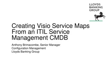
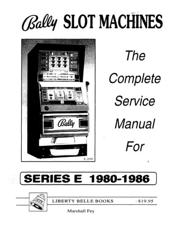
Listed below are the standard loads which the CPU isprogrammed to activate in this test.If a certain loadis not used in a model, its address or code is skipped inthe test.Some models may require additional lighting and,therefore, additional output circuits.In these modelsunused BITS of PORTS #3, #4 and all of PORT #5 are used. Ifstill more outputs are required, an additional output boardwill be used.For the exact sequence of this test, refer to the individualmodel 01120120112021204120812101220Tilt LampDoor Open LampInsert Coin LampCoin Accepted LampJ.P. Tower LampWinner Paid LampCoin Lockout CoilCoin Deflector CoilHandle Release CoilChime or BellGong or BellDoor Alarm 1420CodeDescriptionPayline or Odds LampsandAdditional FeatureLampsReel SolenoidReel SolenoidReel SolenoidReel SolenoidReel SolenoidReel 1500 series only usedon models which requireadditional outputsNote: OUTPUT PORT #0is not used in this test. It ischecked in tests #4 and #5.test continuesSlIIOLII Tn" 8708DB Tn" 015016II J2II Tnru lID81 Tn" liDCI Tn" tiDAll Tbru ABO811 Tnru 880ell Tnru tiDPili '0. 4131-1- -137-1- -771-11E-587-1 l stRIPTilIElectfG-tacnatic tic Displayf.t IsedUlctr.--lalnetic eric Displaylot Used1l IGOP.C. Connector - lottn EntryItot UsedDiode lIW4814 DIGET DOUBLEPROGRESSIVE DISPLAYThe fourteen electro-Magnetic Display unit,shown here, was utilized on machines that hadprogressive jackpots that offered wins up to 99,999.99. A optional sixteen meter unit wascapable of mega-wins- one penny shy of tenmillion. The single unit below shows the lightingsequences that make possible the displays ofnumbers from 0 through 9.ISIBISlsisisialIs.or,.!O.COM.9
Step 3.SWITCH TESTPress TEST button three times.Example:[[[[[ While button is depressed-I rn II II rnT:Jlf[l '-,. 1.J· 0For approximately one second afterbutton is released, then . . [[[[DUntil test is aborted or a switchis closed (a normally closed switchmust be opened first)s[[m-mlllWhile coin switch held closedL : .Example: 5[irnrnGl . t :JWhile hopper roller arm at rest(after lifting it once), untilsome other switch is actuated.Switches not included in test:Power Switch, Door Switch,Change Button Switch, TEST, RESETswitches, Coin Return Switch on"IKE" Dollar Machines. For thecode associated with each switch,see individual model information.test continuesThe COIN SWITCH is locatedon the inside of the FrontDoor immediately belowthe Coin Acceptor./' iY/The LEVEL SWITCHis located at thebase of theHopper.The OPTO HOPPERSWITCH is locatedabove the Hopper PinWheel. On later models. theOpto Switch was replaced bya Micro Switch.The DOOR SWITCH is locatedbehind.
These microprocessor driven slots were popular with the casinos offering better dependability and security. Three years later, a new revamped line, dubbed the SERIES E-2000, were brightened-up with new artwork, the replacement of the dull 6-8 volt lights in the to