Transcription
Network‐on‐Chip Architecture: AnOverview‐‐Md Shahriar Shamim & Naseef Mansoor12/5/20141
Overview Introduction Multi‐core chip Challenges Network‐on‐Chip Architecture Regular Topology Irregular Topology Emerging Interconnect Conclusion12/5/20142
Multi‐core Chips: A Necessity Need for explosivecomputational power Consumer/EntertainmentApplication Scientific Application Increasing clockfrequency is not possibleas it increases powerdissipationSolution: Core level Parallelism,distribute tasks to multiple cores12/5/20143
Challenges: Interconnection of Cores Traditional Interconnectarchitectures are notscalable Delay limit number of coresSolution: Scalable interconnect infrastructurefor communication12/5/20144
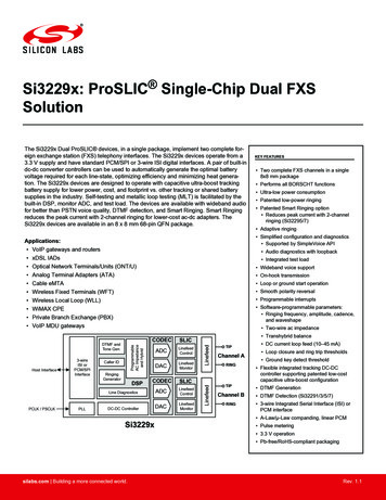
Network‐on‐Chip (NoC) Packet based on‐chip network Route packets, not wires –Bill Dally, 2000. Dedicated infrastructure for data transport Decoupling of functionality from communication A plug‐and‐play network independent of the coresHigh-performanceARM processorHigh-bandwidthmemory interfaceHigh-bandwidthARM processorAHBBRIDGETimerUARTAPBKeypadPIODMA BusmasterAMBA bus: ARMNoC infrastructureMultiple publications in IEEE ISSCC, 2010 from Intel, IBM, AMD, and SunMicrosystems show that multi-core NoC is a reality12/5/201455
SwitchingCircuit Switching Dedicated path, or circuit, is established over which data packets willtravel Naturally lends itself to time‐sensitive guaranteed service due toresource allocation Reservation of bandwidth decreases overall throughput and increasesaverage delaysPacket Switching Intermediate routers are now responsible for the routing of individualpackets through the network, rather than following a single path Provides for so‐called best‐effort services Sharing of resources allows for higher throughput12/5/20146
Switching MethodologyWormhole Switching Message is divided up into smaller, fixed length flow units called flits Only first flit contains routing information, subsequent flits follow Messages must cross the channel entirety before the channel can beused by another message decreases channel utilizationVirtual Channels Allows for several instances of wormhole switching Additional buffers are added, which increases overall switch size, butsignificantly increases throughput12/5/20147
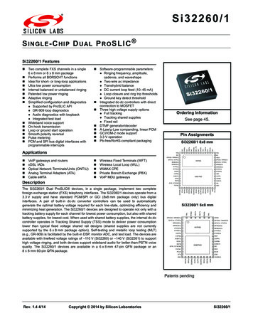
Typical NoC Packet lAddressTailDataSNErrorControlDAORSAHOP HOP01.HOPN Header routing and network control information.In the case of distributed routing the information required is the destination and source addressesin the case of source routing the complete routing information is writtenIn the case of variable packet size a length field is required Payload Tail12/5/2014 sequence number error control fields such as hamming code or CRC fields8
Topology Regular topology: Each node has the same numberof neighbors. Example: 2D mesh, 2D torus Irregular topology: For each node, all neighbors ofthat node have distinct degrees. Example: Hierarchical Mesh, Small‐world12/5/20149
2D Mesh simplest and most popular topology for NoCs. Every switch, except those at the edges, is connected to fourneighboring switches and one node. High Average path distance; not scalable12/5/201410
2D Torus layout of a regular mesh except that nodes at the edgesare connected to switches at the opposite edge viawrap‐around routing channels. Every switch has five ports Long links high delay and high power dissipation; not scalable12/5/201411
Hierarchical Mesh Two level Hierarchy Bottom layer Mesh Connectivity Upper layer Switches grouped intosubnets One hub per subnet All switches from one subnetconnected to the hub fromthat subnet Hubs interconnected witheach other in mesh fashion Power hungry Hubs; still has long links12/5/201412
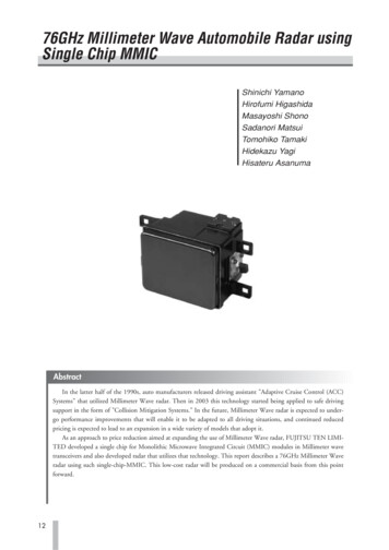
Small World Inspired from nature ‐ microbial colonies, neuralnetworks and social networks Characterized by many short links and few long linksL Avg. Path distanceC Avg. Clustering Coefficient ratio between existing edgesto possible edges betweenneighborafter all .It’s a small world .12/5/201413
SW Topology Construction Small‐World topology Inherently fault‐tolerant Link Insertion Following adjacent probabilitydistributionlij fij P(i, j) lij fij i j Few high speed shortcuts. Local, shorter links.This image cannot currently be display ed.12/5/201414
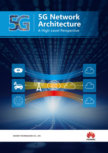
Interconnect Limitation of Wireline Interconnect Multi‐hop wireline communication High Latency and energy dissipationsourcedestination-core-NoC interface-NoC switch80% of chip power will be from on-chip interconnects inthe next 5 years – ITRS, 200712/5/20141515
Emerging Interconnect TechnologiesGoal:High Bandwidth Low Energy DissipationThree DimensionalIntegrationWirelessInterconnectsOptical Interconnects12/5/20141616
3D Integration Stacking multiple active layers Manufacturability Mismatch between various layers Yield is an issue Temperature concerns Despite power advantages, reducedfootprint increases power density Pavlidis et al., “3-D topologies for Networks-on-Chip”, IEEE Transactions on Very Large ScaleIntegration (TVLSI), 2007.12/5/20141717
Optical Interconnect High bandwidth photonic links for high payloadtransfers Challenges: On‐going research On‐chip integration of photonic components A. Shacham et al., “Photonic Network-on-Chip for Future Generations of Chip Multi-Processors”,IEEE Transactions on Computers, 2008.12/5/20141818
Wireless Interconnect Wireless NoC based on Low power and high bandwidth wirelessinterconnectsWireless port/wireless interface (WI)consists of transceiver and antenna Antenna Technology: Metal zigzag antennas (mm‐wave)are CMOS compatible3 Transceiver J. Lin et al., “Communication Using Antennas Fabricated in Silicon Integrated Circuits,” IEEE Journalof Solid-State Circuits, vol. 42, no. 8, August 2007, pp. 1678-1687.12/5/201419
Where should We bet our money?Wireless? Photonics? 3DIntegration?12/5/20142020
Comparisons3D NoCDesign 5/2014LowerPowerPhotonic NoCWireless NoCMultiple layers withactive devicesSilicon photoniccomponentsOn‐chip antenna andtransceiverHigher connectivity& less hop countHigh speed opticaldevices and linksSingle hop shortcutsShorter averagepath lengthNegligible powerdissipation inoptical datatransportEnergy Efficientwirelesstransmission1. Heat dissipationdue to higherpower density2. FabricationProblem1. Integration of on‐chip photonic1. Limitedcomponentsbandwidth2. Crosstalk between 2. Large areaadjacentoverheadwavelengthsNo Clear Winner!!2121
Conclusion Networks‐on‐Chip is a natural choice formulticore processors. Copper wires are power hungry needfor alternative interconnects NoC research is still in primary stage.Finally !!! Many open research problems Need standardized development approach,better application and traffic models, newoptimization techniques12/5/201422
Questions?12/5/201423
3D Integration Pavlidis et al., “3-D topologies for Networks-on- Chip”, IEEE Transaction s on Very Large Scale Integration (TVLSI), 2007. Stacking multiple active layers Manufacturability Mismatch between various layers Yield is an issue