Transcription
ACC ESS CO N T RO L S TA R T ER K I TSOFTWWARE INSTALLAATION
READ THIS BEFORE YOU STARTThis document contains a lot of useful information to help you install and configure theStanley PAC Access Software as effectively as possible. If you cannot read the entiredocument then at least take note of the points in the box below - Thank You.IMPORTANT POINTS:Make sure you have the Stanley PAC USB Flash Drive and Stanley USB Admin ReaderCheck the current PC Operating System requirements before attempting to install the StanleyPAC software. Supported operating systems are listed at www.stanleypac.com/sysreqEnsure that all connected doors have had there functionality checked using the One-Touch TestCard supplied with the Starter KitTECHNICAL SUPPORTIf you need help then call support on this number:(800) 414 3038Option 1
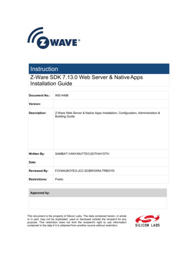
Software InstallationNNonNoe sideSecurreSecure side512IP2I Access ControllerSTTAANLEY PPAAC USB SticktiDoor contactct0VDTRRXCTSTXSeriaal No.Mo d el No .PAC Paartt No .SEALED RECHARGEABLE LEADLEAD-ACID BATTERY12V BATTERYMullion ReadMuderREXXKeyey FobobLANNWindowsoPCAdmin ReaderadSTANLEY PAC Installation How-to, Step by StepPERFORMING A NEW INSTALLATION OF STANLEY PACThis guide is divided into 3 Chapters:➊ InstallationAfter inserting the USB Flash Drive, the Installer Menu provides quick3-step software installation:➊ Software Installation➋ USB Admin Reader Driver Installation➌ Assigning an Fixed IP Address to the PAC 512IP➋ Software Setup WizardThe wizard (setup assistant) presents a sequence of well-definedsteps setting up the key components of an access control database.➌ Full Software Installation Guide4
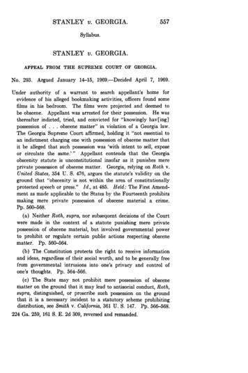
SOFTWARE INSTALLATIONINSTALLER MENUInsert the USB memory stick into an available USB port.The Installer Menu will autolaunch.Check the PC Requirementsfor Stanley PAC atwww.stanleypac.com/pcreqFollow the 3 Steps highlighted below.Once the software is installed, install the USB Admin Readerand set the IP Address for the Two-Door Controller.On completion, an Wizard will guides through setting up thekey components of an access control database.5CHAPTER 1
SOFTWARE INSTALLATION➊ SOFTWARE INSTALLATIONFrom the USB Flash Drive Start Screen, click Install Stanley PAC iconNote an Internet connection may be needed if the PC does not already haveMicrosoft .NET Framework 3.5 installed.Click Launch InstallIf any client PCs are required on the system, select theInstall Client Only on those PCs when this installation is complete.INSTALLING COMPONENTSThe installation detects what components need to be installed.This process is automatic and requires no intervention – but may takea few minutes.The SQL Server 2012 R2 Service Pack 2 installationmay take some time. No intervention is required.You will see progress screens like this:6CHAPTER 1
SOFTWARE INSTALLATION➊ SOFTWARE INSTALLATIONSOFTWARE INSTALLATIONWhen all the components are installed, including the SQLServer, the Stanley PAC software will install.Click Next7CHAPTER 1
SOFTWARE INSTALLATION➊ SOFTWARE INSTALLATIONThe next item is End-User Software License.Select I accept the license agreementClick NextPrompt to enter User InformationClick NextInstaller Contact Information promptThe End-User will see this information in the Help About.Click Next8CHAPTER 1
SOFTWARE INSTALLATION➊ SOFTWARE INSTALLATIONSelect the destination folder for the application. Leave the defaultsetting unless there is a particular reason to make a change.Click NextSelect the default Backup and Archive locations. The system willusually find another drive letter other than C: if it can.Click NextClient access promptEven if you do not have client PCs in the system now, you may inthe future. Check the box now to allow client access.Click Next9CHAPTER 1
SOFTWARE INSTALLATION➊ SOFTWARE INSTALLATIONLoad the Default database (An empty database can always berestored later).Click NextSelect the time zoneClick Next or go back to make changes.Progress screens.10CHAPTER 1
SOFTWARE INSTALLATION➊ SOFTWARE INSTALLATIONThe installation is complete.Click FinishThe final step is to initialize the database.The Stanley PAC software is now installed.Click Close11CHAPTER 1
SOFTWARE INSTALLATION➋ SOFTWARE INSTALLATIONUSB ADMIN READER SOFTWARE INSTALLATIONFrom the USB Flash Drive Start Screen, click the Admin Reader Installer iconUsing the supplied USB cable, plug the USB Admin Reader into a spare USB port.The USB Admin Reader will light up with a red colorThen check the box Administration Reader is connectedChoose the Launch Install buttonIf using Windows Vista or later and the User Account Control dialogbox appears, choose the Yes button.The Device Driver Installation Wizard dialog box is displayed.Choose the Next button.Wait while the software is installed.Choose the Finish button.12CHAPTER 1
SOFTWARE INSTALLATION➌ SOFTWARE INSTALLATIONCONTROLLER IP ADDRESS CONFIGURATION➌From the USB Flash Drive Start Screen, click the 512IP ConfigurationBy default a PAC 512IP is set to obtain an IP address automatically (DHCP).It is recommended that a fixed IP is assigned to the device, typically a 192.168.1.* type address.With DHCP, each time the router restarts (due to power failure etc.), there is no guarantee that it will assign the same IP address to your 512IP Door Controller(s).Setting a fixed IP on the router tells it to reserve an IP address to a particular device and remains saved even if the router is powered off. The end result is that youcan power on and off the router and 512IP, and the router will always assign the same IP address.Note. If the PAC 512IP it fails to receive a dynamic address from a DHCP server it will assign itself an automatic address in the 169.254.xxx.xxx rangeChoose the Launch Tool buttonAn Instructional Video is available, illustrating the steps below.Note the serial number that appears in the table.This is the barcode serial number on the controller.If you have more than one 512IP on the subnet identifeswhich one you are setting up.Double-click the line with the controller, or highlight theline and click Entry.Enter the IP Address, Subnet Mask and Default Gateway then click OK.These values must be provided by the local network administrator.13CHAPTER 1
SOFTWARE INSTALLATIONSOFTWARE CONFIGURATIONDESKTOP ICONOnce the Stanley PAC software is installed there will be a new icon on the Windows desktop,Double-click on this icon to launch the software.Under Windows 8 in tablet mode, a tile is also available on the Start Screen iconSTART SCREEN (WINDOWS 8 AND 10 ONLY)14CHAPTER 2
SOFTWARE INSTALLATIONSOFTWARE CONFIGURATIONLOGIN FOR THE FIRST TIMENow that Stanley PAC is installed, login is required. All activity within Stanley PAC is controlled by login credentials. These determine whatfunctions the operator can perform and what they can see and change.There is no default login; instead the system will requires the creation of a password for the ‘Installer’ operator. ‘Installer’ is the highestlevel operator and cannot be deleted; although it can be renamed.ALARM ALERTSAlarm Alerts is a feature of Stanley PAC that provides pop-up messages even when nobody is logged into the system – for example:This feature needs a credential to determine what can be displayed. A prompt for this credential is presented before the first login. In mostcases you should create the Installer credential at this point and then use it to logon at the main logon prompt.STARTING STANLEY PAC FOR THE FIRST TIMEWindows 8Click or touch the Stanley PAC tile.Before the main logon screen appears you will be promptedto create a login for Alarm Alerts.If you select Not Now, then you will be prompted later.If you select Disable Alerts, you will not be prompted againuntil you enable alerts.You will be prompted to create a password.Click OK.Enter and then confirm a password of at least six characters.Although you can change this at any time, this is your password forinstalling the system. Do not forget it!Click OK15CHAPTER 2
SOFTWARE INSTALLATIONSOFTWARE CONFIGURATIONLOGIN FOR THE FIRST TIMEThe new password is set.Click OK.You should now start Stanley PAC for the first time.You should login with a user name of Installer and use thepassword just created for Alarm Alerts.If you did not create a login for Alarm Alerts you will now beprompted to create a password for the Installer operator.Click Log on.You are now logged in as 'Installer'16CHAPTER 2
SOFTWARE INSTALLATIONSYSTEM CONFIGURATION WIZARDThis is the screen you will see when you first login.The Stanley PAC Software Installation Wizard will automatically launch and provides a step-by-step setup wizard that will haveyour access control system configured and running in minutes.Before this can be attempted you should ensure that all the controllers and communication equipment have been installed.The Default Database installed during the software setup stage can now be configured with the wizard,for systems with up to 16 Doors.To stop the Wizard loading each time the software is launched,uncheck the “Show this form when the application starts”The Wizard can be manually launched from either the Menu Bar icon orthe Tools Menu Start Wizard17CHAPTER 2
SOFTWARE INSTALLATIONHARDWARE SETUPIn the Hardware Setup stage, Door Controllers are assigned to a Channel andeach given a name, it should be something that makes sense.The Default Database has 8 pre-configured controllers, making it easy toset up a 16 Door system.A Channel is the communication path used to the controller.The Starter Kit controller uses a TCP/IP network connection,Select Hardware Setup from the WizardSelect the 512IP Channel icon and Click NextThis will return a list of all the devices connected using TCP/IP, identified bythe serial number of each IP controller configured during softwareinstallation.Select the deviceClick NextSelect the first available controller configuration from the list,in this case Controller 118CHAPTER 2
SOFTWARE INSTALLATIONHARDWARE SETUPClick the Rename Controller icon and type in a name for the controller- it should be meaningful.Drag (or click Assign) the controller configuration onto the serial numberof the relevant controller.Click NextClick Return to the wizard list19CHAPTER 2
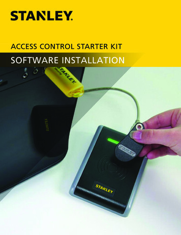
SOFTWARE INSTALLATIONAREA CONFIGURATIONIn the Area Configuration stage, Door Controllers are assigned to an area.An Area is a designated section of a facility with one or more readers,and each should be given a name, it should be something that makessense.A brief over view of Area Management is available from the wizard pageOUTSIDEWhen you assign an access group to an area, any cardholder with thataccess group is granted access to all doors into that area.Notice there is an area called Outside and cannot be removed. It isusually used for configuring readers that leave the building.Office Staff have access to the lobby area, meeting room area, office 1and Office 2 areas, corridor area but not the warehouse area, betweenbetween 9am and 5pm.OUTSIDEOUTSIDEIn the Building illustration, warehouse associates may only have accessto the warehouse area. This means they can access any of the threedoors into the warehouse, between 8am and 5pm.WAREHOUSEOFFICE 1BREAK ROOMCORRRIDOROFFICE 2MEETING ROOMManagers might have an access group that grants access 24/7 to allareas.LOBBYOUTSIDE20CHAPTER 2
SOFTWARE INSTALLATIONAREA CONFIGURATIONSelect Area Configuration from the WizardThe wizard offers 8 predefined Areas and an Outside Area.(The Outide Area is grayed out as it can not be changed)Click an Area icon (1 - 8) and type a name for the Area- it should be meaningful.If more or less Areas are needed, use the or - buttonsWhen complete, Click NextCheck Return to the wizard listClick Finish21CHAPTER 2
SOFTWARE INSTALLATIONTIME PROFILES CONFIGURATIONIn the Time Profile Configuration stage, Door Controllers are assigned to an area.Time Profiles define all the periods during which a reader, key fob or other functionis active or inactive. There are a set of enable and disable times applied to days ofthe week and holidays.Select Time Profiles Configuration from the WizardThere are two options, select the Simple Weekday icon,This can be used for several functions, but is typically used to restrictemployee access to certain areas at particular times.Click NextChoose a template that matches the typical work week.By choosing Simple Weekday 8-5, employees key fobs will only be able to accessspecific areas between 8am and 5pm.Click NextCreate a Door Profile,Check Set-up another time profileClick Finish22CHAPTER 2
SOFTWARE INSTALLATIONTIME PROFILES CONFIGURATIONSelect the Door Profile icon,This profile tells door when to lock and unlock. The door will unlock at thestart and lock again at the end. This is often used to automatically unlock alobby door in the morning and secure it at the end of business.Click NextChoose a template that matches the typical work week.By choosing Door Profile Weekday 8-5, any door to which this is applied will beunlocked at 8am and locked at 5pm.Click NextCheck Return to the wizard listClick Finish23CHAPTER 2
SOFTWARE INSTALLATIONSETUP DOORSIn the Setup Door stage, the door channels are configured.Select Setup Doors from the WizardBy default 16 doors are displayed. Doors are given a default name in theform door controller name n (where n is door 1 or 2), select the dooricon to configure.Click NextChoose a name for the door, something that makes sense.Each door channel can support an Entry Reader (SIGA) and an optional secondEntry Reader (can be used for disabled user access) or as an Exit Reader (SIGB).Select the area that best represents the area the door opens into.SIGB defaults to No reader connected.Click NextA door profile can be applied that will automatically unlock the door between theselected times. If none is selected, the door is always locked and only opens forvalid cardholders.Select a Door Profile from the drop-down menuClick Next24CHAPTER 2
SOFTWARE INSTALLATIONSETUP DOORSThe door setup is complete.To configure additional doors,Check Set up another doorOtherwise, Check Return to the wizard listClick Finish25CHAPTER 2
SOFTWARE INSTALLATIONDEFINE ACCESS GROUPSIn the Define Access Groups stage, cardholder access to where and when is defined.When deciding what access groups are required, you should determine how thesystem will be used by the customer. An Access Group defines the relationshipbetween the doors and the times when a user has access through them. Thismight be by work function, for instance Managers, Sales Department, Maintenance andIT etc; based on where people work by building or floor, for instance or a mix of both.Select Define Access Groups from the WizardSelect one of the two Access Groups provided. More can be added orremoved with the and - buttonClick NextFrom Access Profile 1, define the areas that this access group can accessusing the check boxes. Then apply an optional time profile that limitsbuilding access to between specific times.If required, an Access Profile 2 can be applied with a different Time Profile.For example, in a building with exit readers, it is good practice to provide24/7 access to the outside area to avoid locking people on site after hours.Click NextTo configure additional Access Groups,Check Set up another access groupOtherwise, Check Return to the wizard listClick Finish26CHAPTER 2
SOFTWARE INSTALLATIONADD CARDHOLDERSIn the Add Cardholders stage, the wizard enables quick enrolling of new users.Cardholders are the people that use the access control system, identified to thesystem by a card, key fob or PIN (or a combination of any of these). Every person whoneeds access to the facility must have a record. Once a cardholder has been added tothe system using the USB Admin Reader, a decision can be made at each doorwhether they are permitted or denied access.Select Add Cardholders from the WizardThe first time Add Cardholders is run, the USB Admin Reader must beconfigured.Click the Communication Port and select the COM portClick NextTest that you selected the correct COM port.Click Click to testPresent a key fob included with the kit or the One-Touch test cardYou will be presented with the card or fobs unique ID numberClick Next27CHAPTER 2
SOFTWARE INSTALLATIONADD CARDHOLDERSADD CARDHOLDERSHave a new key fob or card ready to enrollPresent the key fob to the USB Admin Reader and the screen willautomatically advance to the next screenLast NameFirst NameTitleInitialsYou must enter a Last Name(Optional)(Optional) Select from drop-down menu or enter another(Optional)Select the appropriate level of access for the cardholderClick NextCheck a radion button to make a selectionClick Finish28CHAPTER 2
SOFTWARE INSTALLATIONFINAL COMMISSIONINGThe Final Commissioning stage consists of two steps. The first is required andensures that all the changes that have been made by the wizard are downloaded to thecontroller(s). The second, is an optional walk test to check door functionality.Select Final Commissioning from the WizardSelect the channel(s)Click NextClick Next29CHAPTER 2
SOFTWARE INSTALLATIONFINAL COMMISSIONINGMTESTPsecenfor 4 froom grea tionSTTA InstallatonINSlatchh’h’ but will laPersonOnelere Touc lelerr ‘On is control LED.ollettrolthisderreleaser con ched to thehe reawilldeder. locthhee doorss attatta deede byRea thhhe lockas .asedPreess rearreadeprop vidl releaEEntry cee andis prncek wilAll the edbbackto the d oncder. the lockeecard h rednddAll fethis will fflas h Exit Rea andnt ththPPrreesederr LLED arrd ttoards.carade thisimemRReeadthlnttwilwiP esederr LEDPre.ade thRReeadimeim steateperLOOpreaadeerReeadOpeORST EDuring the installation of the hardware, all the door hardware will have beenthroughly tested using the simple One-Touch Test Card.If you require an additional test at the door, an optional Door Release Test can beperformed. It is not required to complete the installation.EODRUCHA DEEERADE-TOE REON.ATT THAhourNGfor oneT IINmodeT ESDoor.testivateI O Ng at thethac ivT IOto act.to dsto redconLL A Tesstin1Optional Stage - Door Release TestingSelect an Area to test from the list of available areas on the leftClick Issue RTEThe system test the door lock and RTE by isuing an RTE and unlocking thedoors.Click NextA Timed Walk Test option enables a series of doors to be walk tested.Click Add StepFrom the Issue RTE at menu, chose a DoorOptional Add Additional StepsClick Start StepsWalk building and confirm door operationClick Finish30CHAPTER 2
SOFTWARE CONFIGURATIONSERVICESStanley PAC installs and configured four 'Services' on the Host PC – these are not installed on a Client PC.1. Communications Engine – this is the process that handles all communications with the access control devices.2. Client Manager – this handles connections from Client PCs.3. Event Manager – this processes events that arrive from the controllers.4. Database Manager – this handles connections to the databaseThese services start when the PC starts up. The user interface does not need to be running for these services to operate. That means a PC canbe shut away and not be logged on to the network or domain, but still act as Host for the Client PCs.These services are controlled by the Service Manager. This appears as small light brown 'door' icon ion the Windows Taskbar.The ‘door’ icon may be hidden by default on your system, simply clicking on the You can start the Service Manager by right-clicking the icon and select 'Open Service ManagerThis brings up the Stanley Service Manager.From here you can start or stop individual services. However most of the time theseshould be set to start automatically and should be running continuously.31CHAPTER 3
SOFTWARE INTERFACEThis is the screen you will see when you first login.Notice the text in the bottom left 'Demo Version'. This is because the system is not yet licensed.The System Summary indicates how many cardholders, doors etc have bee
Card supplied with the Starter Kit TECHNICAL SUPPORT If you need help then call support on this number: (800) 414 3038 Option 1. 4 Software Installation. t . Using the supplied USB cable, plug the USB Admin Reader into a spare USB port. The USB Admin Reader will light up with a red color Then check the box Administration Reader is connected