Transcription
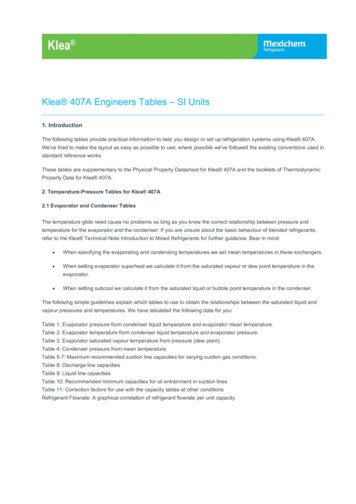
Application Note 046Measuring Temperature withRTDs – A TutorialA resistance-temperature detector (RTD) is atemperature sensing device whose resistance increaseswith temperature. An RTD consists of a wire coil ordeposited film of pure metal. RTDs can be made ofdifferent metals and have different resistances, but themost popular RTD is platinum and has a nominalresistance of 100 Ω at 0 C.RTDs are known for their excellent accuracy over awide temperature range. Some RTDs have accuraciesas high as 0.01 Ω (0.026 C) at 0 C. RTDs are alsoextremely stable devices. Common industrial RTDsdrift less than 0.1 C/year, and some models are stableto within 0.0025 C/year.RTDs can be difficult to measure because they haverelatively low resistance (100 Ω) that changes onlyslightly with temperature (less than 0.4 Ω/ C). Toaccurately measure these small changes in resistance,you may need to use special configurations thatminimize errors from lead wire resistance.Because an RTD is a passive resistive device, youmust pass a current through the device to produce ameasurable voltage. This current causes the RTD tointernally heat, which appears as an error. Selfheating is typically specified as the amount of powerthat willraise the RTD temperature by 1 C, or 1 mW/ C. Youcan minimize self heating by using the smallestpossible excitation current. The amount of selfheating also depends heavily on the medium in whichthe RTD is immersed. An RTD can self heat up to100 times higher in still air than in moving water.The Relationship ofResistance andTemperature in RTDsCompared to other temperature devices, the output ofan RTD is relatively linear with respect totemperature. The temperature coefficient, called alpha(α), differs between RTD curves. Although variousmanufacturers may specify alpha differently, alpha ismost commonly defined as the change in RTDresistance from 0 to 100 C, divided by the resistanceat 0 C, divided by 100 C:α(Ω/Ω/ C) (R 100 - R0 )/(R0 * 100 C)where R 100 is the resistance of the RTD at 100 C,and R 0 is the resistance of the RTD at 0 C.For example, a 100 Ω platinum RTD withα 0.003911 will measure 139.11 Ω at 100 C.Figure 1 displays a typical resistance-temperaturecurve for a 100 Ω platinum RTD.400300Resistance ure ( C)Figure 1. Resistance-Temperature Curve for a 100 ΩPlatinum RTD, α 0.00385Product and company names are trademarks or trade names of their respective companies.340557B-01 Copyright 1996 National Instruments Corporation. All rights reserved.November 1996
Although the resistance-temperature curve isrelatively linear, accurately converting measuredresistance to temperature requires curve fitting. TheCallendar-Van Dusen equation is commonly used toapproximate the RTD curve:As shown in Figure 2, the voltage drop across thelead resistance, RL , adds to the measured voltage.IEXR t R 0[1 At Bt2 C(t - 100)3 ]V0where R t is the resistance of the RTD attemperature t, R 0 is the resistance of the RTD at0 C, A, B, and C are the Callendar-Van Dusencoefficients shown in Table 1, and t is thetemperature in C. For temperatures above 0 C, theC coefficient equals 0. Therefore, for temperaturesabove 0 C, this equation reduces to a quadratic. Ifyou pass a known current, I EX , through the RTD andmeasure the output voltage developed across theRTD, V0 , you can solve for t:t RLRTRL-Figure 2. Two-Wire RTD MeasurementFor example, a lead resistance of 0.3 Ω in each wire,R L, adds a 0.6 Ω error to the resistance measurement.For a platinum RTD with α 0.00385, the resistanceequals a 0.6 Ω/(0.385 Ω/ C) 1.6 C error.2(V 0 I EX R 0 )If you are using lead lengths greater than 10 ft, youwill probably need to compensate for this leadresistance. The preferred RTD measurement methodis to use a four-wire RTD. One pair of wires carriesthe current through the RTD; the other pair senses thevoltage across the RTD. Because only negligiblecurrent flows through the sensing wires, the leadresistance error of RL2 and RL3 is negligible. Thisconfiguration is illustrated in Figure 3.I EX R 0 [A A 2 4B(V 0 I EX R 0 ) / I EX R 0 ]where V0 is the measured RTD voltage and IEX is theexcitation current.Most platinum RTD curves follow one of threestandardized curves–the DIN 43760 standard(α 0.00385), the U.S. Industrial or Americanstandard ( α 0.003911), or the InternationalTemperature Scale (ITS-90) that is used with wirewound RTDs (α 0.003925). The Callendar-VanDusen coefficients for each of these three platinumRTD curves are listed in Table 1.IEXRL1RTD Measurement CircuitsRL2 Because the RTD is a resistive device, you mustdrive a current through the device and monitor theresulting voltage. However, any resistance in thelead wires that connect your measurement system tothe RTD will add error to your readings. Forexample, consider a two-wire RTD elementconnected to a measurement system that also suppliesa constant current source, I EX , to drive the RTD.V0RTRL3-RL4Figure 3. Four-Wire RTD MeasurementTable 1. Callendar-Van Dusen Coefficients Corresponding to Common RTDsStandardTemperatureCoefficient (α)ADIN 43760AmericanITS-900.0038500.0039110.0039263.9080 x 10 -33.9692 x 10 -33.9848 x 10 -3B-5.8019 x 10 -7-5.8495 x 10 -7-5.870 x 10 -7C*-4.2735 x 10 -12-4.2325 x 10 -12-4.0000 x 10 -12* For temperatures below 0 C only; C 0.0 for temperatures above 0 C.2
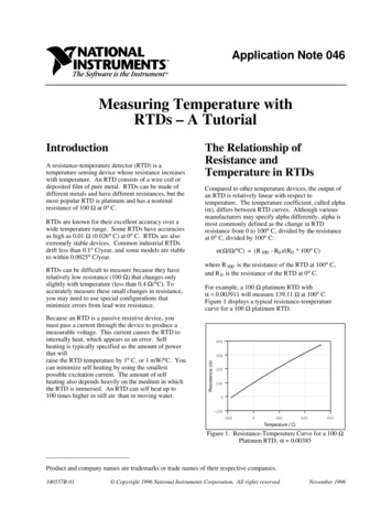
To reduce costs, you may instead want to use a threewire RTD. By using the three-wire RTD in aWheatstone configuration with a current source, asshown in Figure 4a, you can compensate for the leadresistances. Notice that, in this bridge configuration,the effects of RL1 and RL3 cancel each other outbecause they are located in opposite arms of thebridge. Lead resistance RL2 does not add significanterror because little current flows through it.Alternatively, you can use a current excitation sourceand connect the three-wire RTD as shown inFigure 4b. In this configuration, the resistance ofonly one lead, R L1 , adds error to the measurement.Signal Conditioning eXtensions for Instrumentation(SCXI) is a signal conditioning front end you can usewith plug-in DAQ boards, or as a complete, externalDAQ system. SCXI modules condition signals from avariety of signal sources, such as RTDs, thermistors,and thermocouples, and pass the conditioned signalto the plug-in DAQ board. The plug-in board canthen acquire the signals directly into PC memory.Alternatively, you can connect the SCXI system to anRS-232 or RS-485 serial network to a PC for remotedata acquisition.The SCXI product line has a variety of analog anddigital signal conditioning modules for various typesof signals. The SCXI-1121 and SCXI-1122 are wellsuited for RTDs.IEXThe SCXI-1121 is an isolated amplifier andmultiplexer module with four isolated input channels.Each of the four channels has a jumper-selectablegain amplifier (gains from 1 to 2,000) and a lowpassfilter (4 Hz or 10 kHz). The SCXI-1121 also has fourchannels of isolated voltage or current excitation.You can configure each channel independently toproduce a constant 0.15 mA, 0.45 mA, 3.333 V, or10.0 V source.RL1R1RTRL2-V0R2 RL3R3a. Three-Wire RTD in a Wheatstone ConfigurationThe SCXI-1122 is a 16-channel isolated multiplexermodule with a programmable amplifier (gains from0.01 to 2,000) and a single 1.0 mA currentexcitation source.IEX V0-RL1RL2RTExample–Monitoring 16 RTDs withthe SCXI-1121RL3For this example, assume that you want to use 16100 Ω four-wire RTDs to monitor the efficiency of aproduction process. You can monitor all 16 RTDswith four SCXI-1121 modules installed in a four-slotSCXI-1000 chassis. The modules and chassis areconnected to a plug-in PC DAQ board that acquiresthe analog signals from all four modules and storesthe digitized readings into PC memory.b. Three-Wire RTD with a Current Excitation SourceFigure 4. Three-Wire RTD Measurement with aWheatstone Bridge and a Current SourceRTD Measurements withSCXIThe plug-in board in this example is theAT-MIO-16F-5, which is a 12-bit, 200 kHzmultifunction I/O board for IBM PC AT andcompatible computers. The AT-MIO-16F-5 board isused in the example because of its accuracy, highscan rate, and self-calibration capability. You canalso use similar multifunction I/O boards for theMacintosh and PS/2 platforms with the SCXI system.The SCXI chassis is connected to the AT -MIO-16F-5with the SCXI-1345 shielded cable assembly, whichis available in lengths up to 10 m. The RTDs arewired into SCXI-1320 terminal blocks, which haveconvenient screw terminals with strain relief.Figure 5 is a diagram of the system.Signal conditioning is generally required to interfacean RTD to a measurement device such as a plug-indata acquisition (DAQ) board. Signal conditioningproduces current excitation for the RTD, amplifiesthe output signal, and filters the signal to removeunwanted noise. You can also use signalconditioning to electrically isolate the RTD and themonitored sytem from the DAQ system and the hostcomputer.3
CXI1100SCXISMSCCAI114XIXNF0IRA11M0016RTDsE4 SCXI-1320Terminal Blocks4 SCXI-1121ModulesSCXI-1000ChassisSCXI-1345Shielded CableAssemblyAT-MIO-16F-5DAQ BoardFigure 5. SCXI System for Monitoring 16 RTDsAn IBM PC/XT/AT or compatible computer controlsthe temperature monitoring system. Therefore,application software choices for controlling thesystem include National Instruments' LabWindows for DOS or LabVIEW for Windows. Alternatively,you can use a general-purpose programminglanguage such as C, BASIC, or Pascal in DOS orWindows and control the DAQ hardware with theNI-DAQ driver software that is included with allNational Instruments plug-in DAQ boards.3.Table 2 summarizes a typical SCXI-1121configuration for measuring RTDs.Table 2. Typical Configuration for an SCXI-1121Used with RTDsConfiguring an SCXI System forRTD MeasurementSCXI-1121ParameterFirst, configure the SCXI-1121 modules for the RTDmeasurements. Configuring includes setting theexcitation mode, gain, and bandwidth for each inputchannel of the SCXI-1121. Follow these steps toconfigure your SCXI-1121 modules:1.Set the bandwidth. The SCXI-1121 has jumperconfigurable filters on each channel. You can seteach filter for a cutoff frequency of 4 Hz or10 kHz. The 4 Hz filter is particularly useful forrejecting 60 Hz noise from power lines andlighting.Channel gainBandwidthExcitation modeExcitation levelBridge completionSet the Excitation mode. Because you are usingfour-wire RTDs, configure each channel forconstant current excitation. You can configurethe current source for 0.15 mA or 0.45 mA. Thelower current setting minimizes the RTD selfheating effect.Note:Typical Settingfor a 100 ΩFour-Wire RTD1004 HzCurrent0.15 mADisabledThese settings are configured on a perchannel basis.Connecting the RTDs to theSCXI-11212. Set the gain. Determine what gain to applyto your RTD signal. Be careful to choose thegain so that the output of the SCXI-1121 doesnot exceed the 5 V input range of theAT-MIO-16F-5, but produces the optimumresolution. For example, suppose you willoperate your 100 Ω RTD at a temperature up to300 C. At this temperature, the RTD resistanceincreases to about 220 Ω. With a 0.15 mAcurrent source, the voltage output at 300 C willbe 220 Ω * 0.15 mA 33 mV. Setting the gainof the SCXI-1121 to 100 will generate amaximum voltage output of 3.3 V, which iswithin the 5 V input range of the plug-in board.Connect the RTDs to the SCXI-1121 module with aSCXI-1320 shielded terminal block. Alternatively,you can use the SCXI-1321 or SCXI-1328 terminalblocks, which have special capabilities for straingauges and thermocouples, respectively, or theSCXI-1330 connector and shell. Figure 6 shows thewire connections used to correctly wire a four-wireRTD to channel 0 of an SCXI-1320.4
MODULE TYPERed WireBlack Wire11211120CH 0CH 0 —EX 0CH 1 —CH 1CH 2EX 1CH 3CH 2CH 4EX 2CH 5CH 3CH 6EX 3CH 7Red WireBlack WireRTDStrain Relief — — — — — —CHASSIS GNDCHASSIS GNDSCXI-1320Safety Earth Groundfor HighCommon-Mode Voltage( 42 Vrms)Figure 6. Connecting a Four-Wire Platinum RTD to Channel 1 of the SCXI-1320Figure 7 contains wiring diagrams for connecting two-wire, three-wire, and four-wire RTDs to the SCXI-1121module.SCXI-1121 Module withCurrent Excitation EnabledEX RedCH RedIEX -SCXI-1121 Module withCurrent Excitation EnabledEX RTD - -RTDBlackCH -EX -BlackEX -a. Four-Wire RTD ConfigurationIEXRedSCXI-1121 Module withCurrent Excitation andBridge Completion Enabled EX CH IEXRTDBlackEX -Blackc. Three-Wire RTD ConfigurationBlackb. Two-Wire RTD ConfigurationYou make this connectionCH -RedCH IEXCH -SCXI-1121 Module withCurrent Excitation EnabledEX You make these connections -CH -RedBlackRTDCH EX -BlackRD (user supplied)d. Alternative Three-Wire RTD ConfigurationFigure 7. Wiring Diagrams for Two-Wire, Three-Wire, and Four-Wire Configurations5
SCXI Single Chan Setup, AI Read,and AI VScale. The AI VScale functionreturns the voltage measured on the RTDchannel.Measuring RTD TemperatureAfter you have configured and installed the plug-inDAQ board and SCXI-1121 modules and havecorrectly wired the RTDs to the SCXI terminalblock, you can measure the temperature yourRTDs sense.3.You can use LabVIEW, LabWindows, or NI-DAQsoftware to easily monitor the voltages that theRTDs generate. The following softwareprogramming sequences are typical for taking anRTD measurement using each software package.LabVIEWBridgeVIEWUse this programming sequence with LabVIEW:1.2.3.Run the NI-DAQ Configuration Utility andinput the SCXI hardware configuration andjumper settings. This step informs the NI-DAQdriver software of which hardware is beingused and how the modules are configured,including which gain value to use whenscaling the data.Measure the voltage from the RTD channel.You can use high-level VIs such as AI SampleChannel and AI Sample Channels, which arein the Easy I/O palette of the DAQ menu, tomeasure the voltage from one or more of theSCXI channels.Scale the voltage measurement to atemperature reading. LabVIEW has a virtualinstrument (VI) that uses the Callendar-VanDusen equation to scale your voltage readingto a temperature reading. This VI, RTDConvert, is in the DAQ Utilities palette of theDAQ menu.1.Run the NI-DAQ Configuration Utility(WDAQCONF.EXE) and input the SCXIhardware configuration and jumper settings.2.Use the DAQ Channel Wizard to configureeach I/O channel. For each I/O channel, youconfigure scaling and assign a tag name. Youcan select RTD scaling from a pop-up dialog.The NI-DAQ Server will automatically scalevoltage measurements from the SCXI-1121into temperature using the proper RTD transferfunction.3.From within your BridgeVIEW application,read the tags assigned to your RTD inputs.Data will be returned in scaled temperatureunits.NI-DAQUse this programming sequence with NI-DAQ:1.Run the NI-DAQ Configuration Utility andinput the SCXI hardware configuration andjumper settings. This step informs the NI-DAQdriver software of which hardware is beingused and how the modules are configured.2.Measure the voltage from the RTD channel.For single-point voltage measurements, usethe function sequence SCXI Load Config,SCXI Single Chan Setup, AI Read,and AI VScale. The AI VScale functionreturns the voltage measured on the RTDchannel.3.Scale the voltage measurement to atemperature reading. NI-DAQ has source codeLabWindows/CVIUse this programming sequence with LabWindowsfor DOS:1.Run the NI-DAQ Configuration Utility andinput the SCXI hardware configuration andjumper settings. This step informs the NI-DAQdriver software of which hardware is beingused and how the modules are configured.2.Measure the voltage from the RTD channel.For single-point voltage measurements, usethe function sequence SCXI Load Config,Scale the voltage measurement to atemperature reading. LabWindows hasconversion functions that use the CallendarVan Dusen equation to scale your voltagereading to a temperature reading. Thesefunctions, RTD Convert for single-pointconversions and RTD Buf Convert formultiple conversions, are part of theTransducer Conversions instrument driver(convert.fp).6
files that implement the Callendar-Van Dusenformula to scale your voltage reading to atemperature reading. These files are calledRTD.c, RTD.pas, and RTD.bas for the C,Pascal, and BASIC programming languages.You can also use the current excitation channels ofthe SCXI 1121 module to power multiple RTDsconnected to additional SCXI-1120 eight-channelisolation amplifier modules. A single SCXI-1121excitation channel can drive a constant currentsupply through a load of up to 10 kΩ. If each RTDresistance will be limited to 250Ω, for example, asingle SCXI-1121 excitation channel can power upto 40 RTDs in a serial configuration.Low-Cost RTDMeasurementsFor simpler, low-channel count RTD applicationsthat do not require the flexibility and expandabilityof SCXI, the SC-2042-RTD signal conditioningaccessory delivers a very cost-effective solution.The SC-2042-RTD is an 8-channel signalconditioning board that cables directly to a plug-inDAQ board or PCMCIA card (Figure 9). The SC2042 includes eight independent constant currentsources to power eight RTDs with screw terminalsfor 4-wire connections. The SC-2042-RTD operateswith a variety of DAQ devices in differentialmode, including MIO Series and E Series boards,DAQCard-1200, DAQPad-1200, and the Lab-PC .The RTD application example in this applicationnote uses the SCXI-1121 isolation amplifier. TheSCXI-1121 module has four isolated andindependently configurable excitation channels foreach of the four isolated input channels. Ifchannel-to-channel isolation is not important, youcan configure a less expensive system by using theSCXI-1122, which includes one current excitationsource to power multiple RTDs., as shown inFigure 8.IEXConclusion R T1-RTDs are versatile temperature sensors that havehigh accuracy over a wide range of temperatures.Because RTDs are low-resistance devices, youmust be careful when wiring and measuring RTDsto avoid errors caused by lead resistance. Signalconditioning such as current excitation andamplification is required to make RTDmeasurements with DAQ equipment. A NationalInstruments SCXI signal conditioning system hasconfigurable current excitation, amplification,filtering, and electrical isolation for your RTDapplications. With the SCXI system, you cancondition multiple RTD signals and pass themultiplexed signal to a PC plug-in DAQ board.V1 R T2R Tn -V2VnFigure 8. RTD Measurement with SCXI-1122Plug-in DAG BoardUp to 8 RTDsor voltage inputsSC-2042-RTDSignal Conditioning AccessoryFigure 9. SC-2042-RTD Configuration7PCMCIA DAQCard
system include National Instruments' LabWindows for DOS or LabVIEW for Windows. Alternatively, you can use a general-purpose programming language such as C, BASIC, or Pascal in DOS or Windows and control the DAQ hardware with the NI-DAQ driver software that is included with all National Instruments plug-in DAQ boards. Configuring an .