Transcription
&EYQ /YRWXWXSJJI QF, E IVQER GSQTER] ! " # % !& ! '() & " * "! , , , - *!%(.*%/ *01% ** / / !& % 2324 567889: & " ' ( , ) /#& % , XIWXMRK F] XLI /SVVSWMSRWMRWXMXYXIX SJ 7[IHIR XVEGIEFMPMX] WTEVO ERH L]HVS XIWXMRK ! " # %&" ' ;MXL &EYQ W WXVMRKIRX UYEPMX] TVSKVEQW XIWXMRK XVEGIEFMPMX] ERH TIVQERIRX QEVOMRK XLI LMKLIWX
Technical SpecificationsThese specifications define the material, technical data, installation instructions and qualitychecks for our PTFE/PFA, PVDF and PP lined pipe and fittings.They are in accordance with ASTM F1545-97 (2003) for general requirements,ANSI B16.5 for dimensions and B31.3 for pressure piping.Contents4. Baum Part Numbering System1. Materials1.1 Steel parts5. Chemical Resistance1.2 Lining5.1 PTFE1.3 External coating5.2 PFA5.3 PP2. General Technical Data2.1 Pressure Equipment Directive6. Products(97/23/EC)2.2 Steel pipe dimensions7. Pipe and Flange Dimensions2.3 Flange connections2.4 Liner thickness2.5 Liner thickness/vacuum resistancetable2.6 Operating temperatures2.7 Operating pressures2.8 Vacuum resistance2.9 Vent holes2.10 Tolerances2.11 Protective covers3. Quality Management3.1 Welding3.2 Material certificates3.3 Raw materials checks3.4 Optical and dimensional checks3.5 Spark tests3.6 Hydrostatic tests3.7 Marking3.8 Certificates3
1. Material1.1Steel parts1.1.1 All steel pipe (carbon steel) meets ASTM A106 Gr. B, A587 Gr. B ERW, or A53 Gr. B ERW1.1.2 Flanges comply with ASTM A1051.1.3 Fittings comply with ASTM A234 Gr. WPB1.1.4 Stainless steel is supplied per customer specification.1.2Lining1.2.1 Liner Physical Properties (test method: ASTM D638)PROPERTYPTFEPFAPPPVDFSp. Gravity2.14 – 2.192.11 – 2.17.901.75 – 1.784,5003,8003,0005,000350-40030030050Melt Point625580338340Max. Service Temp.( F)450450225275NaturalNaturalOrangeBlackTensile Strength (psi)Elongation (%)Colors1.2.2 Plastics ConductivityDIN/EC 60093 and DIN/EC 60167 does not exceed 108 Ohm.1.2.3 FDA ComplianceUpon customers’ request the lining of our piping parts complies with the regulations ofthe Food and Drug Administration (FDA).1.3External Coating1.3.1 SandblastingAll carbon steel parts are sandblasted according to SSPC-SP6.1.3.2 Paint coatingAll carbon steel pipes are painted with an epoxy-zinc-chromate primer to protect themfrom corrosion.4
2. General Technical DataPlease consult chemical resistance chartfor temperature limitations for particular2.1 Pressure Equipment Directivechemistries.(97/23/EC)If the piping parts are applied withinthe pressure equipment directive(PED), they fulfill all requirements ofconstruction, manufacturing andtesting.2.7Operating PressuresTemperature Maximum Pressure Rating(w/ 150# flanges)100oF250 psig150oF242 psig200oF235 psig215 psig300oF400oF200 psig500oF170 psig2.8 Vacuum Resistance2.2 Steel pipe dimensionsSee chart below.Steel pipe according to ASTM A106Gr. B: Standard Wall. Fittings according to ASMEB16.9.2.9 Vent HolesVent holes should be kept open at alltimes. They have a dual function. First,2.3 Flange connectionsFlange connections comply withANSI B16.5 (Class 150 and 300).they allow permeating gas to escape.Second, they serve as leakage indicatorsto ensure rapid repair.2.4 Liner thicknessAll Baum liner thicknesses meet or exceed those2.10 Tolerancesspecified in ASTM F1545-97(2003). Our linerTolerances of pipe and fittings arethickness is intended to maximize your cost/benefitdefined in ASTM F1545-97 (2003) as wellposition while assuring vacuum and permeationas in ASME B16.5. The liner thicknessresistance.may vary approximately.10%. This applies especially to the area2.5 Please refer to chart below for liner thicknesses.of the flares where the liner thickness isup to 20% thinner by definition.2.6 Temperature Operating RangesPolymerTemperature RangePTFE-20o to 500oFPFA-20o to 500oFooPP0 to 225 FPVDF-20o to 275oF2.11Protective CoversFlares are protected with a water proofplywood cover or plastic cap. All boltsand nuts are galvanized and can easilybe loosened.5
General Technical Data2.5Liner Thickness & Vacuum ResistanceNPS (in)11-1/2234681012Liner Vacuum (in. ltFactoryTemperature ( yLiner Vacuum (in. Hg)FullFullFullFullFullFullFullFullFullTemperature ( F)225225225225225225225225225Liner Thickness(in.).125.125.125.125.145.160.185Vacuum (in. Hg)FullFullFullFullFullFullFullTemperature ( F)275275275275275275ConsultFactoryPTFE / PFAPPPVDFNote 1: All vacuum data reflects testing done per ASTM F1545 -97(2003).Note 2: 1”-8” fittings meet or exceed pipe liner thickness and vacuum ratings for same size and linermaterial. Vacuum ratings for 10” and larger fittings may have limitations. Consult factory.Note 3: Vacuum ratings may not apply for short stack crosses, laterals, crosses, special angle elbows andsight flow indicators 4” and above. Consult factory.Note 4: Certain chemicals may affect vacuum ratings. Consult factoryNote 5: Larger sizes require special attention. Factors such as length of spool, rapid cool down and suddenpressure drops should be anticipated and vacuum breakers should be considered.6
3. Quality Management3.1 Welding3.5 Spark testsOur welding processes are subject toAll lined pipe (not conductive) and fittingsthe following criteria:undergo a 25.000 Volt spark test to verify1. We are a recognized manufacturercontinuity.in accordance with AD-MerkblattHPO/TRD 201/DIN EN 729-2.3.6 Hydrostatic tests2. Our processes conform toThe hydrostatic test is conducted at 1-1/2ADMerkblatt HP 2/1 & ANSI B31.3times nominal working pressure. Baum pipe3. Our operations are supervised byand fittings are both spark and hydro tested.a recognized welding expert.This exceeds the ASTM requirement which4. We only employ welders with anspecifies either a spark test or hydrotest.HP 3 certificate (i.e. Certifiedwelders)3.7 MarkingIn accordance with ASTM F 1545-97 (2003),3.2 Material certificatesevery factory pipe and fitting will be markedAll pipe, flanges, elbows and weldedon the flange's circumference asfittings have a works certificatefollows:according to EN 10204-3.1.B.Manufacturer's signProduction lot3.3 Raw material ChecksLining materialLining materials are only procuredDate of productionwith material certificates WAZ 2.3CE marking (if applicable)from manufacturers certified acc. toAdditional markings – e.g. material no. – areISO 9001.available upon customer demand.In addition, our own laboratorycontinually checks and records thephysical data of semi-finishedproducts from the production line.3.4 Optical and dimensional checksThe dimensions of all pipe and fittingsare checked visually.7
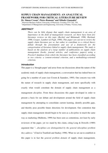
3. Quality Management3.8 Certificates8
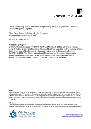
4. Baum Part Numbering System9
5. Chemical Resistance5.1 PTFE has a universal chemical resistance6. PRODUCTS - This documentation is basedagainst almost all chemicals and solventson past experience. All information is to thewithinbest of our knowledge and is given withoutitscontinuousoperatingtemperature range with the exception ofresponsibility.molten alkalis, elementary fluorine andcertain halogens.We assume no liability with respect to theexecution and nature of our products as well5.2 PFA is identical with PTFE.as their performance.5.3 PP - Please consult website. Please note:We reserve the right to make productPP and PVDF chemical resistance canchanges without prior notice.change with temperature andconcentration of media.We reserve the right to change the liningmaterial between PTFE and PFA based onprocessing capability.7. Pipe and flange dimensions for lined pipes and fittingsFlange OD (in)NPSPipe Schedule wall thkRaisedFace Dia(in)Pipe OD(in)StandardWall thk 84.631.691.0500.1130.1131"1 1/2"2"2 .4380.5000.5620.5940.688Class 150Other schedules available upon .2770.3070.3300.3750.3750.4380.5000.562Sch40
Lined Pipe (Class 150 and Class 300)Fixed - FixedFixed X RotatingRotating x RotatingL (inch)NPSStd. Pipe Sch½”¾”1"1 ½”Lining XX4040240.00240.002.953.15XXXXXX2"40240.003.54XXX2 51XXXSpools can be ordered with ductile iron flanges where service allows.11
Spacers (Class 150 and Class 300)Spacers in Form F and G are also available as tapered spacer with a variety of angles.Lining materialNPS12PTFEPPPVDF1/2”XXX3/4”XXX1”XXX1 1/2”XXX2”XXX2 X14”X16”X18”X20”X24”X
Blind FlangesLNPSClass 150(L) inchClass 300(L) inchLining materialPTFE1/ 2”0.470.67X3/ 4”0.500.75X1”0.560.81X11 /2”0.690.93X2”0.751.00X12 24”1.882.87X13
Elbows 30 & 60oNPS½“3/ 4”1”1½”2”2 �24”Class 150L 507.508.009.408.90Lining MaterialsPTFEXXXXXXXXXXXXXXXXConstruction dimensions for Class 300 upon request.30o & 60o elbow dimensions are not defined in but have been calculated following ANSI B16.5.Please specify the desired lay length when contacting BAUM.14
Elbows 45 & 90o45o elbowsNPS90o elbowsClass 150 Class 300 Class 150 Class 300L (in)L (in)L (in)L (in)Lining MaterialPTFEPPPVDF½“3/ 0012.0022.00XNominal pipe sizes 1/2" and 3/4" are not defined in ASME B16.5.PP and PVDF are only available with fixed flanges.15
Tees5” & above are 2-piece constructionNPS1NPS2Class 150L (in)Class 300L (in)1/2"3/4"3/4"1"1"1"1 1/2"1 1/2"1 1/2"2"3"1/2"3/4"1/2"1"3/4"1/2"1 1/2"1"3/4"1” - 2"1” - �12"14"16"18"20”24”1” - 4"3” - 6"4” - 8"4” - 10"6” - 12"8” - 14"10” - 16"12” - 18"14” - 20”16” - PTFELining XXXXXXNominal pipe sizes 1/2" and 3/4" are not defined in ANSI B16.5. Please determine the desired laylength when contacting BAUM. PFA-lined Tees are also available as Lateral-Tees upon request.16
CrossesNPS1NPS2Class 150L (in)Class 300L (in)1/2"3/4"3/4"1"1"1"1 1/2"1 1/2"1 1/2"2"1/2"3/4"1/2"1"3/4"1/2"1 1/2"1"3/4"1” - 3.754.004.004.004.504.504.505.00PTFELining ” - 3"5.506.004"1” - 4"6.507.00X6"3” - 6"8.008.50X8"4” - 8"9.0010.00X10”6" – 10”9.0010.00X12"6” - 12"12.0013.00X14"8” - 14"14.0015.0016"10” - 16"15.0016.50X18"12” - 18"16.5018.00X20”14” - 20”18.0019.50X24”16” - 24”22.0022.50XNominal pipe sizes 1/2" and 3/4" are not defined in ASME B16.5. Please determine the desired laylength when contacting BAUM.PP & PVDF crosses are available with fixed flanges only.17
Instrument TeesNPS1NPS21"1"1"1 1/2"1 1/2"1 1/2"Class 150Class 300H (in)4.334.334.33Lining Material1"3/4"1/2"1 1/2"1"3/4"L (in)2.002.002.003.002.002.00H (in)3.543.543.544.334.334.33L (in)2.002.002.003.002.002.00PTFE1 1/2"1/2"2.004.332.002"2"2"2"2"1 X3"3"3"3"3"2"1 he dimensions of instrument tees are not defined in ASME B16.518PFAXXXXXXXXXXX
Instrument Tees (cont’d)2"1 1/2"Class 150L (in)H (in)4.005.913.005.91Class 300L (in)H (in)4.006.693.006.694"4"4"6"6"6"6"6"1"¾"½"2"1 XXXX8"8"8"8"8"2"1 XX10"10"10”2"1 12.80XXXXXX12”12”12”1” - 2"1 Lining MaterialPFAPPXXXXPVDFXXXThe dimensions of instrument tees are not defined in ASME B16.5.19
Reducing FlangesClass 150Lining materialL (in)FormPTFEPFA3/4"½"1.38K3X1"½” – ¾"1.38K3X1 1/2"1"1.38K3X1 1/2"3/4"1.38K2X2"1 1/2"1.38K3X2"1"1.38K2X2"3/4"1.38K2X3"2"1.38K2X3"1 1/2"1.38K2X3"1"1.38K1X4"3"1.77K3X4"2"1.77K2X4"1” - 1 1/2"1.77K1X6"4"1.77K2X6"1” - 3"1.77K1XX8"6"1.77K2X8"1” - 4"1.77K1X10"8"1.77K2X10"6"1.77K1X10"1” - 4"1.77K1X12"10"1.97K2X12"1” - 8"1.97K114"12"1.97K2X14"1” - 10"1.97K1X16"14"1.97K2X16"1” - 12"1.97K1X18"1” - 16"1.97K1X20"18”1.97K2X20"1” - 16"1.97K1X24”1” - 20”1.97K1XClass 300 concentric/eccentric reducing flanges available upon request.NPS120NPS2
Concentric ReducersClass 150/300NPS13/4"1"1 1/2"1 "18"20"20"24”24”NPS21/2"1/2"1"3/4"1 1/2"1"2"1” - 1 1/2"3"2"4"3"6"4"8"6"10"6” - 8"12"8” - 10"14"10” - 12"16”12” - 14"16” - 18”14”18”14” - 16”L 0019.0019.0020.0020.0024.0024.00FormLining nal pipe sizes 1/2" and 3/4" are not defined per ANSI B16.5. Please determine the desired lengthwhen contacting BAUM.21
Eccentric Reducers22NPS1NPS23/4"1"1 1/2"1 16"16"20"20"20"20"24”24”24”1/2"1/2"1"3/4"1 1/2"1"2"1 1/2"1"3"2"4"3"6"4"8"6"10"8"6"12"8” - 10"14"12"10"16” - 18"14"18"14” - 16"20"18"16"Class 150/300L XXXLining XXXXXXXXXXXXXXXXXXXXXXXXXXXXXXXXX
Bull’s Eye Sight Indicators (Class 150)Class 150NPSL 001"1 ½”2"3"4"6"8"10"12"14"16"FormAAAAABBBBBBLining materialPTFEPFAXXXXXXXXXXXBall Check Valves (Class 150)NPSClass 150 L (in)Lining Material - PTFE1"1 XXXX
PTFE Expansion Joints, 2 convolute, Class 150NPS1/2"3/4"1"1 1/2"2"2 .017.289.06Maximum Allowable .390.390.390.390.397777777777777777Vacuum Resistancein Hg@ max. 113113in Hg@max. . The above shown chart is only valid at neutral length and with limit bolts in place.2. Above mentioned types of travel (axial, lateral or angular) are considered independently.The percentage values must not exceed 100% when added together.3. The figures stated are average values at room temperature.4. Bolt holes are threaded.5. Class 300 and other designs are available upon request.24
PTFE Expansion Joints, 3 convolute, Class 150NPS1/2"3/4"1"1 1/2"2"2 .1711.0212.87Maximum Allowable 4Vacuum Resistancein Hg@ max. 113113inHg@ max. . The above shown chart is only valid at neutral length and with limit bolts in place.2. Above mentioned types of travel (axial, lateral or angular) are considered independently.The percentage values must not exceed 100% when added together.3. The figures stated are average values at room temperature.4. Bolt holes are threaded.5. Class 300 and other designs are available upon request.25
PTFE Expansion Joints, 5 convolute, Class 150NeutralNPS1/2"3/4"1"1 1/2"2"2 1/2"3"4"6"8"10"12"14"16"18"20"Maximum Allowable 0202020202020202020202020202020Vacuum ResistanceNot Recommended for Vacuum Service1. The above shown chart is only valid at neutral length and with limit bolts in place.2. Above mentioned types of travel (axial, lateral or angular) are considered independently.The percentage values must not exceed 100% when added together.3. The figures stated are average values at room temperature.4. Bolt holes are threaded.5. Class 300 and other designs are available upon request.26
' ! & ( ' ! )* , ( (3 238 VIQSZI JPERKI TVSXIGXSVW YRXMP TMTI ERH !"# %
checks for our PTFE/PFA, PVDF and PP lined pipe and fittings. They are in accordance with ASTM F1545-97 (2003) for general requirements, ANSI B16.5 for dimensions and B31.3 for pressure piping. Contents 1. Materials 1.1 Steel parts 1.2 Lining 1.3 External coating 2. General T