Transcription
Rev. January 2019Bubble‐Up Jr Interactive Installation and Operating InstructionsU.S. Patent # 6,372,024 and 8,393,875Installation and Service By:The Bubble‐Up Interactive unit from R.E. Prescott Co., Inc. is designed to remove radon gas from water. Radon is a radioactive gaswhich can cause serious health problems. Inside the unit, air is blown into the incoming water and allowed to bubble upward. Thisbubbling action releases the radon from the water. Air containing the radon is then collected and vented out.
Bubble‐Up Jr Interactive Radon Removal SystemTable of ContentsSpecificationsInlet and Outlet Flow and Pressure SpecificationsControls and IndicatorsInstallationStart‐Up ProcedureOperating InstructionsMaintenanceTrouble ShootingReplacement Parts ListingStart‐Up DataStart‐Up Notes347812121314202324AppendixA‐ 7 gpm Mechanical Head ManualB‐ Meter Control ManualC‐ Bubble‐Up Warranty252830Manufactured by:R.E Prescott Co., Inc.10 Railroad Avenue Exeter, New Hampshire 03833Phone: (603) 772‐4321 Fax: (603) 772‐1089REPRESCOTT.COM2
Bubble‐Up Jr Interactive Radon Removal SystemSpecificationsDimensions:Depth: 18” Width: 24” Tank Height: 41”Overall Height: 60”Maximum water depth: 26” (off float switch level)Refill water depth: 19” (on float switch level)Run dry water depth: 5”Cycle Tank:2.1 Gallon, 3/4” MNPT, 8” Diameter X 10” Tall, Water Expansion TankWater Capacity:On/Off Cycle Volume: 7 GallonsUsable water at maximum water depth of 26”: 34 GallonsUsable water at refill water depth of 19”: 27 GallonsApproximate Weight:90 lb. empty373 lb. filled to maximum water depth of 26”507 lb. filled to overflow water depth of 41”Influent Water Requirements:Hardness 68 mg/l (4 GPG)Iron 0.03 mg/lManganese 0.05 mg/lPlumbing Connections:1” male npt water inlet and outlet bypass valve2” FNPT air inlet with nipple for directly mounting Bubble‐Up Jr Interactive blower2” Fernco air outlet1.25” fnpt overflow connection3/4" Male npt for expansion tankElectrical:Dedicated 20A circuit, Quadplex outlet, 115V AC #12 AWG wiringPump:1/2 HP high pressure (75 p.s.i.) submersible pump10.6 A maximum (running) @ 115VBlower:4.5A, 115V ACSolenoid Valve:7 GPM Standard, 1/2” fnpt, CV 2.0, 115V coil for 7 gpm, or14 GPM Adder, 3/4" fnpt, CV 5.0, 115V coil for 14 GPMMotorized Ball Valve:7 GPM, 1/2" Standard or 14 GPM, 3/4" Adder3
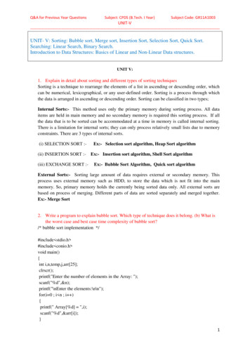
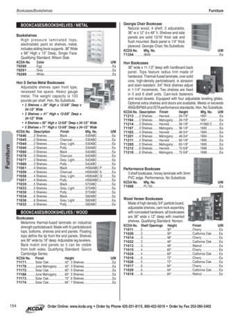
Bubble‐Up Jr Interactive Radon Removal SystemPump controller:Bubble‐Up Mechanical Pump Control with a low water float switch, 7 GPM Standard or 14 GPM Adder, protects thepump from running dry, integral check valve, and operates the pump from a 2.1 gallon tank, 115V ACRadon Removal Efficiency:MODELBubble‐Up Jr Interactive 7 GPM Standard, 1/2” SolenoidBubble‐Up Jr Interactive 14 GPM Adder, 3/4" SolenoidGPMEFFICIENCY799%1498%Inlet Flow and Pressure SpecificationsFigure 1 ‐ Bubble‐Up Jr Interactive Inlet Pressure vs. Flow4
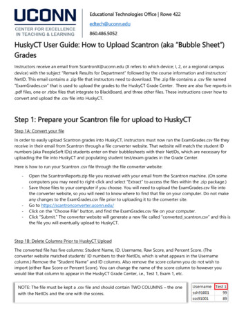
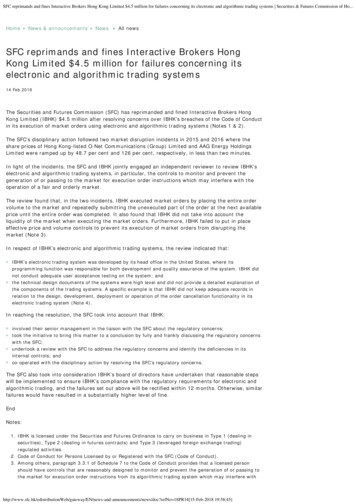
Bubble‐Up Jr Interactive Radon Removal SystemOutlet Flow and Pressure Specifications7 GPM Mechanical Pump ControlPressure vs. Flow80Pressure 1015Flow (GPM)Pressure (PSI)Figure 2 ‐ Bubble‐Up Jr Interactive Outlet Flow vs. Pressure 7 GPM14 GPM Mechanical Pump ControlPressure vs. 4 GPM Pump Control w/ 3/4” Pex0510Flow (GPM)1520Figure 3 – Bubble‐Up Jr Interactive Outlet Flow vs. Pressure 14 GPM5
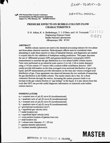
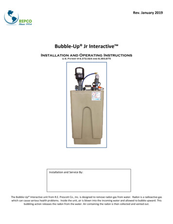
Bubble‐Up Jr Interactive Radon Removal SystemTested ResultsRadon Removal vs. FlowRadon Removal (%)10098969492900510152025Flow (GPM)Figure 4 – Radon Removal vs. Flow 99% Removal at 7 GPM6
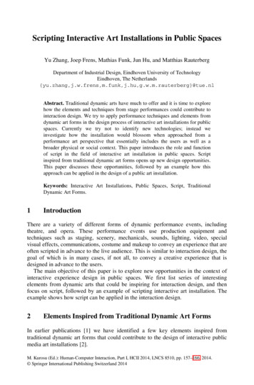
Bubble‐Up Jr Interactive Radon Removal SystemControls and IndicatorsBypass valveThis valve can be used to divert the water flow if a problem develops with the Bubble‐Up Jr Interactive unit.This valve has two red handles, and is located near the back of the unit. See Figure 7. The valve has two positions: Service ‐ This is the normal operating position. When the two valve handles are in line with water flow, the unitcan remove radon from the incoming water.Bypass ‐ When the two valve handles are perpendicular to water flow, the incoming water “bypasses” theBubble‐Up Jr Interactive unit. Use this position only if there is a problem with the unit.Caution! When the bypass valves are set to the Bypass position, the Bubble‐Up Jr Interactive unit cannot provide anyprotection against radon in the water.Meter ControlFor instructions regarding the meter control refer to the Bubble‐Up Meter Control manual in the appendix and online atwww.represcott.comMechanical Pump ControlFor instructions regarding the mechanical pump control refer to the Bubble‐Up Mechanical Pump Control AssemblyOwner’s Manual in the appendix and online at www.represcott.com.Water Alarm ValveThe water alarm valve control is designed to identify leaking problems in the Bubble‐Up Jr Interactive . It is designedto monitor radon vent obstruction, high water and fitting leaks. It does this by incorporating a water alarm valve floatswitch, water alarm floor sensor and water alarm tank top terminal block sensor to signal the water alarm valve controlwhich operates the motorized water alarm ball valve. See figures 13 and 14.Important Feature: The water alarm valve can also be used to create any number of remote leak detection points byconnecting extra leads to the leads of the terminal block.Users Guide: Please choose the correct mode on the mode switch shown in the picture according to the application. In thecase of the Bubble‐Up Jr Interactive , the switch should be in the normal water position. See figure 5* The buzzer will beep if there is a radon vent pipe obstruction, high water alarm or detected water leak, and atthe same time a signal will be sent to the external motorized ball valve. This signal will cause the ball valve toclose and cut off the water supply immediately. To reset the motorized ball valve to its original open position, hold the reset button for three seconds. A yellow light accompanied by the buzzer means that the battery is low. If this occurs replace the battery assoon as possible to avoid any overflows during a power outage.Important information about the Water Alarm Valve: The alarm on this control will go off if there is water inside of thecontrol. If this occurs, fully dry the inside of the control before returning it to service.7
Bubble‐Up Jr Interactive Radon Removal System*Figure 5 – Water Alarm ValveInstallation1. Be sure the float switches are not tangled around the pump by removing the 2” vent fitting and visuallyinspecting the float.2. The Bubble‐Up Jr Interactive comes with a standard 2.1 gallon water expansion tank. Plumb this expansiontank near the outlet of the Bubble‐Up Jr Interactive .Note: This expansion tank can be used for a certain amount of water heater thermal expansion. If you have a tank typewater heater, check manufacturer’s requirements for sizing thermal expansion tank.Radon Testing Note: It is important to install a new sample valve or boiler drain in new piping so that the radon testingis not influenced by old piping.3. Set the main tank of the Bubble‐Up Jr Interactive in the desired location that can hold the weight of theBubble‐Up Jr Interactive shown in the Specification Section on page 2. Choose a flat, level surface with ampleset‐up space.4. In case of a malfunction, the unit could overflow. The Bubble‐Up Jr Interactive is fitted with an overflowpipe. (The overflow pipe is mounted near the rear of the unit. See Figure 7) Take this into account whenpositioning the unit. It is best if the unit can be positioned near a drain or sump pit with a sump pump.5. Depress the high water alarm float so it is flush with the rubber cord seal. (Figure 6)6. Set water alarm sensor on floor and wire to terminal block, one wire on the black connection and one wire onthe red connection.Important note about overflow: The Bubble‐Up Jr Interactive incorporates a high water alarm float switch in the cordseal, a water alarm tank top terminal block sensor and a water alarm floor sensor. The control will operate the wateralarm valve and shut off incoming water when there is an obstruction in the radon exhaust pipe, water around the floorsensor or tank to terminal block sensor, a faulty float switch assembly, tangled float switch assembly, or if the solenoidvalve is stuck open. This water alarm valve has a battery backup and will function during a power outage. However,additional overflow precautions should be taken such as connecting the overflow to a proper drain.Caution! Normally, the output from the pump is at a pressure of 70 PSI. This should not create a problem in aninstallation where the existing plumbing is in good condition. However, in an installation where the existing plumbingcannot withstand the operating pressure of the Bubble‐Up Jr Interactive , the output from the pump may produce a8
Bubble‐Up Jr Interactive Radon Removal Systemstress on the plumbing and cause leaks. In this kind of situation, a pressure regulator should be installed on the outletside of the unit and drawdown tank.7. The Bubble‐Up Jr Interactive requires a quadplex outlet wired to a dedicated 20A circuit. Use a 20 amp duplexGFCI receptacle for the yellow float switch cord for UL (See Figure 8). This circuit should use #12 AWG wiring.8. Install the 2.1 gallon water expansion tank on the outlet side of the unit. See Figure 11. This tank is included toprevent the pump from starting and stopping quickly (“short cycling”) when there are short‐term demands forsmall amounts of water.9. Install a pre‐filter on the inlet side to protect the solenoid from sediment clogging. See figure 11. The pre‐filtershould be a sediment‐type filter with a 5 micron rating. Do not use a carbon‐type filter.10. Attach the red handled bypass valve.11. The bypass valve is included so that the unit can be taken out of service easily without interrupting the watersupply. Plumb the inlet line and outlet line so that the water can continue the water demand if the bypass valveis set to the bypass position.12. Pour one ounce of bleach into the blower attachment nipple to disinfect the unit. See Figure 6 for location ofblower attachment nipple.13. Firmly slip the blower onto the blower attachment nipple and tighten clamp to secure blower to nipple.Caution! Do not use PVC pipe cement on this connection.Note: If blower inlet is connected to draw air from an outdoor source, make sure that no moisture can get into a blowermotor. If an outdoor source is desired, a dryer vent kit can be modified by removing the flap check and replacing it witha screen. Be sure to install the kit as directed and run the hose down to the floor in the area of the Bubble‐Up Jr.Interactive.14. Plug in the following cords. Refer to figures 6, 7, & 8. Plug blower cord into duplex outlet. Plug solenoid cord into duplex outlet. Plug fill piggy‐back float switch cord into yellow float switch cord Plug duplex outlet cord into fill piggy‐back float switch cord15. Plug yellow float switch cord, meter control cord, and water alarm valve cord into dedicated 20 amp quadplexoutlet. See Figure 8.Important note: Do not plug in pump control cord until Bubble‐Up Jr Interactive tank is filled to normal operatingwater depth.16. Run the vent line outdoors using 2” PVC piping. Try to make this line as short and direct as possible*. Make all ofthe pipe connections air tight using proper PVC pipe cement.Important note about vent line piping: Use ¼” per foot pitch towards the Bubble‐Up Jr Interactive .*Caution! Do not install a vent outlet line which is longer than 50’, and includes more than five elbows. This can createexcessive backpressure and interfere with the operation of the unit. On longer runs, use larger pipe. Call the factory fordetails on specific applications. If this is done the blower unit of the Bubble‐Up Interactive can create pressure withinthe main tank. This can cause water from the main tank to be forced up through the overflow pipe and spill onto thewater sensor terminal block thus activating the water alarm valve, shutting down the unit. This can also occur if the ventoutlet line is plugged.Caution! Do not install the vent opening at a location where the vent gasses could be blown back into an occupiedspace.9
Bubble‐Up Jr Interactive Radon Removal SystemImportant information about venting: Since the Bubble‐Up Jr Interactive unit removes radon in the water; the unitmust be vented carefully. Common practice is to run the vent up past the roof line of the building. An elevated ventopening provides the best way of dissipating the radon gas. Protocols recommend extending the vent opening 2’ abovethe highest opening in the building, and at least 10’ away from the nearest opening. It is recommended to protect thevent opening with a vent screen. A single free hard (printed) copy of the ASTM E‐2121 standard (RecommendedResidential Radon Mitigation Standard of Practice) is available from EPA’s National Service Center for EnvironmentalPublications (NSCEP). You can order a copy by phone at 1‐800‐490‐9198, via E‐mail nscep@bps‐lmit.com, or via theinternet at www.epa.gov/nscep/ordering.htm Please use the EPA document number (402‐K‐03‐007) when ordering E‐2121. EPA reprints E‐2121 under agreement with ASTM International.17. Plumb the mechanical pump control and plug pump cord into low water piggy‐back float cord. Plug the lowwater piggy‐back float cord into the female cord of pump control. See Figure 7.18. Check all plumbing fittings to be sure all fittings are water tight.19. The water alarm valve control is wired to the power supply, motorized ball valve, and water sensor terminalblock.20. Install 9V battery backup into water alarm control.21. Terminal block wires are connected to high water alarm valve control, water alarm float switch and water alarmfloor sensor. These wires are twisted together and connected to terminal block.Note: Water Sensor Terminal Block Connection: Connect the water alarm float wire, water alarm control (figure 6), andwater alarm sensor wires to the terminal block (The terminal block is located next to the air vent, figure 7). Connect onewire to the black connection of the terminal block and the other wire to the red connection of the terminal block. It isvery important that this is a good connection.Bubble‐Up Blower2” Blower AttachmentNippleMechanical Pump ControlPlug Blower and Solenoidinto the Duplex OutletAir Water CouplingPump AccessWell SealLow Water Piggy‐BackFloat Cord and HighWater Alarm Float inthe cord sealFigure 6 ‐ Installation Points10
Bubble‐Up Jr Interactive Radon Removal SystemMechanical PumpControl Standard 54/65Pressure SwitchWater Inlet and Outlet(Bypass Valve)Overflow PipeRemove 1 1/4” PlugWater SensorTerminal blockFigure 8 ‐ Power CordsBlack Pump ControlCordWater Alarm ValveCordTypical Quadplex Outlet (outletnot provided) Use 2‐20 ampDuplex ReceptaclesYellow Float SwitchCordMeter Control Cord11
Bubble‐Up Jr Interactive Radon Removal SystemStart Up Procedure1.2.3.4.5.6.7.8.9.10.Set the red handles on the bypass valve to the Service position.Before plugging in Bubble‐Up Jr Interactive , identify the plug‐in cords. See figure 8.Plug in the meter control and water alarm valve control power cords.Push reset button on water alarm valve control for 3 seconds to open the motorized ball valve.Plug in the yellow cord first. The blower should start, and the solenoid valve should open to begin filling thetank.As the water level in the tank rises, the fill float switch will tilt up. This will stop the blower and close thesolenoid valve.Once the tank is full, plug in the black pump control cord.If the pump does not start delivering water to the house, it may be necessary to prime the pump. (Normally youwill only have to do this once, when the unit is first installed.) The pump is suspended by a pipe underneath thepump control. Unscrew the union and move the pump control off to the side. You may need to siphon orvacuum the water up this pipe to remove the air from the pump and prime it.Once the air has been removed from the pump, replace the pump control and tighten the union. Plug in thepump. If the pump does not start delivering water to the house, repeat the priming sequence.After the unit is operating, run a radon test of the raw water and the filtered water to ensure that the unit isreducing radon levels in the water.Radon Testing Note: It is important to install a new sample valve or boiler drain in new piping so that the radon testingis not influenced by old piping.11. Perform the six‐month maintenance procedure, and fill out the Start‐Up Data page at the end of this manual.Operating InstructionsOnce the Bubble‐Up Jr Interactive has been installed, it should operate with very little attention.Normal OperationMain UnitThe unit should not need any operator attention. When water is used in the house, the 2.1 gallon water expansion tankdelivers water demand. When the pressure drops to the set pressure, the mechanical pump control starts the Bubble‐Up Jr Interactive pump to deliver water to the home and refill the 2.1 gallon water expansion tank. When themechanical pump control senses normal household pressure, the mechanical pump control shuts the Bubble‐Up JrInteractive pump off. As the water level falls in the Bubble‐Up Jr Interactive main tank, the float switch powers theblower and solenoid to fill the Bubble‐Up Jr Interactive tank with treated water.Low Water Cut‐Out Float SwitchThe pump will automatically stop when there is low water in the Bubble‐Up tank. The pump will automatically restartwhen water is replenished.Water Alarm ValveThe water alarm valve is in place for protection against leaking or overflowing and will not operate unless one of thesethings happens. Once the water alarm valve control, overflow alarm float, floor sensor or terminal block senses aproblem in the system the water alarm valve control activates the motorized ball valve and shuts off the incomingwater. The water alarm valve control will also sound an alarm to identify that there is a problem.12
Bubble‐Up Jr Interactive Radon Removal SystemBypassing the UnitIf a problem develops, the Bubble‐Up Jr Interactive unit can be taken out of the water supply system with the bypassvalve. The rest of the water system will operate normally, but the Bubble‐Up Jr Interactive will not be able to provideany protection against radon in the water.Caution! Do not continue to operate the water supply system this way for a long time. Correct the problem with theBubble‐Up Jr Interactive and return it to service as quickly as possible.MaintenanceEvery six months: Check the operation of the float, pump control, solenoid valve, and the blower by turning on a water tap andallowing it to run. At first, the water will be supplied by the 2.1 gallon water expansion tank, and then the pumpshould turn on. A few minutes later, you should hear the blower start and the solenoid valve should open. (Theunit cannot remove radon unless the blower is working.) Check the incoming flow rate on the meter control. Typical well pump fill rates are between 4 and 7 GPM.Higher flow rate systems are available. Shut off the water tap. The tank in the Bubble‐Up Jr Interactive unit should fill in less than two minutes. Check the outlet of the vent line to ensure that it is not blocked. Check that the motorized ball valve is operating correctly by crossing the leads of the terminal block or raisingthe high water float, or wetting the floor sensor. This should activate the motorized ball valve and shut off allincoming water. Hold the RESET button on the front of the water alarm valve control for three seconds toreturn the motorized ball valve to its open position after each test. Disinfect the unit as needed. (Pour one ounce of bleach into the blower attachment nipple.) Replace 9‐volt battery in Water Alarm Valve ControlEvery y
Bubble‐Up Jr Interactive Radon Removal System 7 Controls and Indicators Bypass valve This valve can be used to divert the water flow if a problem develops with the Bubble‐Up Jr Interactive unit. This valve has two red handles