Transcription
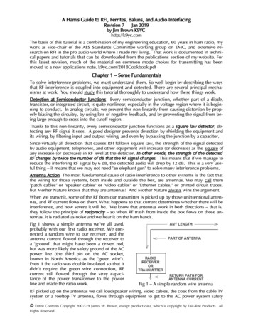
A Ham's Guide to RFI, Ferrites, Baluns, and Audio InterfacingRevision 7Jan 2019by Jim Brown K9YChttp://k9yc.comThe basis of this tutorial is a combination of my engineering education, 60 years in ham radio, mywork as vice-chair of the AES Standards Committee working group on EMC, and extensive research on RFI in the pro audio world where I made my living. That work is documented in technical papers and tutorials that can be downloaded from the publications section of my website. Forthis latest revision, much of the material on common mode chokes for transmitting has beenmoved to a new applications note. k9yc.com/2018Cookbook.pdfChapter 1 – Some FundamentalsTo solve interference problems, we must understand them. So we'll begin by describing the waysthat RF interference is coupled into equipment and detected. There are several principal mechanisms at work. You should study this tutorial thoroughly to understand how these things work.Detection at Semiconductor Junctions Every semiconductor junction, whether part of a diode,transistor, or integrated circuit, is quite nonlinear, especially in the voltage region where it is beginning to conduct. In analog circuits, we prevent this non-linearity from causing distortion by properly biasing the circuitry, by using lots of negative feedback, and by preventing the signal from be ing large enough to cross into the cutoff region.Thanks to this non-linearity, every semiconductor junction functions as a square law detector, detecting any RF signal it sees. A good designer prevents detection by shielding the equipment andits wiring, by filtering input and output wiring, and even by bypassing the junction by a capacitor.Since virtually all detection that causes RFI follows square law, the strength of the signal detectedby audio equipment, telephones, and other equipment will increase (or decrease) as the square ofany increase (or decrease) in RF level at the detector. In other words, the strength of the detectedRF changes by twice the number of dB that the RF signal changes. This means that if we manage toreduce the interfering RF signal by 6 dB, the detected audio will drop by 12 dB. This is a very use ful thing – it means that we may not need "an elephant gun" to solve many interference problems.Antenna Action The most fundamental cause of radio interference to other systems is the fact thatthe wiring for those systems, both inside and outside the box, are antennas. We may call them"patch cables" or "speaker cables" or "video cables" or "Ethernet cables," or printed circuit traces,but Mother Nature knows that they are antennas! And Mother Nature always wins the argument.When we transmit, some of the RF from our transmitter is picked up by those unintentional antennas, and RF current flows on them. What happens to that current determines whether there will beinterference, and how severe it will be. We know that antennas work in both directions – that is,they follow the principle of reciprocity – so when RF trash from inside the box flows on those antennas, it is radiated as noise and we hear it on the ham bands.Fig 1 shows a simple antenna we’ve all used,probably with our first radio receiver. We connected a random wire to our receiver, and theantenna current flowed through the receiver toa "ground" that might have been a driven rod,but was more likely the safety ground of the ACpower line (the third pin on the AC socket,known in North America as the "green wire").Even if the radio was double insulated so that itdidn't require the green wire connection, RFcurrent still flowed through the stray capacitance of the power transformer to the powerline and made the radio work.Fig 1 – A simple random wire antennaRF picked up on the antennas we call loudspeaker wiring, video cables, the coax from the cable TVsystem or a rooftop TV antenna, flows through equipment to get to the AC power system safety Entire Contents Copyright 2007-19 James W. Brown, except product data, which is copyright by Fair-Rite Products. AllRights Reserved
Understanding and Solving RF Interference ProblemsPage 2ground. Hams understand that some antennas are more effective than others. An antenna that isclose to resonance will work better than one that is not. Long antennas tend to pick up more RFthan short ones. Think about these fundamental principles when trying to diagnose which cablesare bringing your RF into a given system (or radiating their trash into your receiving antenna).A path to "ground" or the power system is not always needed to produce antenna action. The whipantenna on our VHF and UHF handheld radios uses the radio, capacity-coupled to our hand thatholds it, as a counterpoise (that is, to provide "the other half of the antenna"). All that is requiredfor this to work is that the size of the counterpoise must be a significant fraction of a quarter wave(or larger) so that it can "sink" the antenna current.Common Mode and Differential Mode Signals A differential mode signal is one that exists between the conductors of a cable. At any given point along the cable, current flowing on one conductor is precisely balanced by current flowing in the other direction on the other conductor. Theintentional signals carried by cables are differential mode signals – the audio or video signal in ahome audio system, Ethernet signals on CAT5/6 cable, and the RF signal carried by the feedlineconnecting our antennas to our transceivers.A common mode signal is one that places equal voltage on all conductors – that is, the voltage between the two ends of the cable are different, but there is no voltage between the conductors. Antenna action produces a common mode voltage and current along a cable. The antenna current induced on audio and video wiring is a common mode signal. That is, with "ideal" cable, there is nodifferential voltage between the signal conductors as a result of this antenna action. If the cable isshielded, nearly all of this current flows on the shield (and skin effect causes it to flow on the outside of the shield). If the shield is ideal (that is, if the current is distributed with perfect uniformityaround it), the field inside the shield will be zero, and thus none of this antenna current will flowinside the cable. Conversely, when a cable shield is carrying differential mode current, as in thecase of coax, skin effect will cause that differential mode current to flow on the inside of the shield.The real world is not ideal, so most interfering signals will simultaneously exist in both commonmode and differential mode, but in most real world conditions, one or the other mode dominates.Several cable defects (essentially manufacturing tolerances) certainly can and do convert this "common mode" antenna current to a differential signal (that is, a voltage between the signal conductors), but that is rarely the most powerful coupling mechanism. One common defect that affectsboth balanced and unbalanced cables is imperfect construction of cable shields. In even the best"real world" balanced twisted pair cables, there are imbalances in the capacitance between "red"and "black" conductors to the shield on the order of 5%. [B. Whitlock, JAES, June 1995] In balancedpaired cables that use "foil/drain" shields, there is even more imbalance in the inductive couplingbetween each conductor and the shield. Noise (or RFI) coupled by this mechanism is called"shield-current-induced noise," or SCIN. [N. Muncy, JAES, June 1995] All three of these mechanisms convert shield current to a differential signal at system input and output terminals.Another imperfection in shielded cable is often quantified as its transfer impedance, which is defined as ratio of the differential voltage induced inside the cable to common mode current on theshield. Its units are Ohms, a low value is better, and the lower limit is the resistance of the shieldat the frequency of interest. The overall quality, percent coverage, and uniformity of the shieldalso contribute to the transfer impedance – a less dense braid or a shield with poor uniformityraise the transfer impedance, causing more noise to couple by this method. Mass-market cablessold to connect home entertainment systems often have very poor quality shields and high transferimpedance. The quality of shields of coaxial cables designed for radio systems varies widely. Likemost other things, you get what you pay for.If the cable is an unshielded pair (loudspeaker cable, for example), RF will be induced approximately equally on both conductors (but, depending what the input circuit of the equipment lookslike at RF, current flow into the equipment may not be equal on both conductors). This can alsoproduce a differential voltage at the input (or output) terminals.Output Wiring is Important Too! It is well known, for example, that RF interference is often coupled into the output stage of audio equipment – for example, the power amplifiers that feed loud-
Understanding and Solving RF Interference ProblemsPage 3speakers or headphones. There is always feedback around that output stage, so RF present at theoutput will follow the feedback network to the input of a gain stage, where it will be detected andamplified. This problem is made much worse when parallel wire cable (zip cord) is used to feedthe loudspeakers or headphones, and can usually be solved simply by replacing the zip cord with atwisted pair of POC (plain ordinary copper). [Pseudo-scientific advertising hype for exotic cablesnotwithstanding, it was shown nearly 30 years ago that #12 copper twisted pair (or #10 for verylong runs) is a nearly ideal loudspeaker cable.] [R. A. Greiner, "Amplifier Loudspeaker Interfacing,”JAES Vol 28 Nr 5, May 1980] As we will discuss later, the twisting of a pair greatly reduces thelevel of RF that the wiring couples to circuitry.Power Supply and Control Wiring can also act as antennas. When I bought the house I owned inChicago, I upgraded the electrical wiring and put all of it in steel conduit (EMT). This shielded thewiring, so that only the short power cords between equipment and the wall outlets could act asantennas. The house I recently bought in California is wired with no conduit, using unshieldedparallel conductors. Thanks to its length, and the fact that it is not shielded, this wiring acts as aneffective receiving antenna for the RF I am transmitting, and an effective transmitting antenna forthe RF trash generated by computer equipment, power supplies for low voltage lighting fixtures,and even battery chargers.Current Returns to its Source Current flows in a complete circuit that includes the source of thecurrent. The circuit will couple noise inductively, and also by antenna action. The cause of manyRFI and noise problems, as well as the solution to them, lies in identifying and controlling thesecircuits. Always ask, "Where does the noise (or RFI) current flow?"Loop Area One of the most fundamental laws of electrical circuits is that the current that is magnetically induced between two circuits is proportional to the loop area of each circuit. Making theloop area small also minimizes the extent to which the wiring can act as an antenna. When we usea closely coupled pair of conductors to form a transmission line, we are reducing the loop area,which reduces the total current induced in the loop by an interfering signal, and the total magneticfield produced by current in that loop. The transmission line, of course, has other useful properties. More on this later on.The equipment designer can also use multilayer printed circuit techniques to place a "ground" (reference) plane next to all signal wiring, turning each circuit trace into an unbalanced transmissionline, where the return current is carried on the reference plane under wiring. A single referenceplane makes a very large reduction in the ability of that circuit trace to receive interference; sandwiching it between two such planes virtually eliminates it. These techniques, called microstrip (oneplane), or stripline (the sandwich), are widely used by better designers. They reject noise couplingboth inside and outside the equipment by drastically reducing the loop area of the current path(and have the additional benefit of making high speed data circuits behave better because they aretransmission lines).Loaded Words That Cause Misunderstandings One of the most overused and misunderstoodwords in electronics is "ground" (or "earth" in British English). There are several important andcommon uses of the words. One meaning is an actual connection to mother earth. Some commonearth connections include the steel structure of a building, a buried conductive water pipe, a con crete encased grounding electrode (called a Ufer, after its inventor, Herbert Ufer), and, of course,one or more conductive rods driven into the earth. [Concrete mixes vary widely in their conductiv ity – most we are likely to encounter are highly conductive, but some are effective insulators.] Theprimary function of this earth connection is lightning protection.A second common use of the word "ground" (or "earth" in British English) is a third conductor thatis part of the power system wiring that should never carry current (except in the case of a fault) butconnects the conductive enclosures of equipment to a common point within the power system.This "green wire" or third pin in the outlet in North American power systems, is called the "equipment ground" (or "protective earth" in British English). The green wire is required to be connectedto all exposed conductive parts of electrical equipment "that might be energized" in the event ofequipment failure. The purpose of this connection is to provide a sufficiently robust current paththat a fuse will blow or circuit breaker will trip in the event of equipment or wiring failure that
Understanding and Solving RF Interference ProblemsPage 4causes the chassis to be "hot," thus protecting people from electrical shock and preventing fires.A third common use of the word "ground" (or "earth" in British English) is to describe "circuit common" or "circuit reference" within equipment. Circuit common should nearly always be connectedto the power supply reference, and to the shielding enclosure of the equipment. If the source ofnoise is within equipment, circuit common is reference for the noise voltage (and current), and it isthe point to which that noise current wants to return.A fourth common use of the word "ground" is as the "return" for an unbalanced antenna like a vertical or long wire. In this application, the antenna needs some conductor to be a low impedance"sink" for the antenna current and a return for the fields produced by antenna current. The radialsfor an elevated or ground-mounted vertical antenna serve this function.Ground Wiring Some hams like to think of the earth as if it were somehow a "sink" into which allnoise can be poured, never to bother us again. Indeed, you'll find lots of bad advice to solve RFIproblems with "a better ground." In fact, nothing could be further from the truth. An earth connection is rarely part of a solution to RF or noise problems. Rather, we need a better understanding ofthe four common meanings of “ground,” that “ground” is not a single point, and that connectionsbetween them change current paths. [There are exceptions to every "rule," and this no exception.See "Shunting Common Mode RF to Earth" later in this tutorial.]Consider a noise filter hanging between some piece of noisy equipment and the power line, withcapacitors from the "hot" and "neutral" to "ground." What is that "ground?" It is circuit common andthe shielding enclosure of the equipment, the green wire in the power cord, which is connected tothe equipment ground in the power system, which goes to the breaker panel, which is in turnbonded to neutral and a real earth connection at the service entrance to our building (and, if we'vedone it right, there should be a bond between the power system ground and any grounds we'veadded for our radio equipment). In most systems, the green wire follows a rather long path – typi cally a quarter wave on 80 meters, and perhaps even on 160 meters. That current path is an antenna, and any RF current flowing on that conductor will radiate! In fact, the connection to earthmay increase current flow. Like any other radiated RF signal, our receiving antennas will hear it. Allof those "ground" connections must be present to have a safe installation, but it is the combinationof the high series impedance of the filter's choke and the connection between the filter's "ground"and the shielding enclosure of the equipment (and it must be very short) that suppresses the noise.The earth connection provides lightning safety.This basic scientific fact has major implications in the design of filters intended to prevent noisecoupling from noisy equipment to our ham stations. If we add a filter to wiring that enters orleaves a piece of noisy equipment, it is the shielding enclosure for that equipment to which any"ground" of our filter should return (and, of course, circuit common should also be connected tothat shielding enclosure). All connections between the filter and the noisy equipment should be asshort as possible (what my old EE professors liked to call "zero length" to emphasize the impor tance of making them short). Why? First, to minimize the loop area, and thus the inductance.Second, to minimize antenna action. More about this when we discuss specific filter designs.Insufficient Input and Output Filtering As hams, we know that equipment needs good input andoutput filtering to prevent RF from coming in on input and output wiring. Beginning in the 1950's,hams operating the HF bands were deluged with TVI complaints because television manufacturersfailed to include high pass filters in their sets. Likewise, audio equipment needs good low pass filtering to reject our signals. Many myopic designers of "high futility" audio gear (and even someprofessional gear) don't include low pass filters because they don't want to degrade the phase response of the audio path. While good phase response is certainly important, so is RF rejection.Good engineering can satisfy both needs without compromise. Ever since those early days, hamshave always assumed that a good low pass filter will kill RFI in audio systems, and a good highpass filter will kill interference to FM and TV. Unfortunately, while good filtering is important, othermechanisms are far more important in most real world situations.Shield Resistance adds hum and buzz to unbalanced wiring (audio, video, and data (RS232). The"green wire" at every AC outlet is at a different potential, thanks to leakage current of equipment
Understanding and Solving RF Interference ProblemsPage 5plugged into that outlet, as well as other leakage current flowing on the green wires. When thatequipment is interconnected with unbalanced wiring, the difference in potential (60 Hz and its harmonics, plus noise) causes current flow on the shield, and the IR drop is added to the signal. A"beefy" shield (big copper) minimizes R – that's why the best video cables use heavy coppershields! Audio transformers eliminate the hum/buzz by breaking the current path at DC and audiofrequencies, but most hum and buzz in your ham station can be solved without a transformer –simply power all interconnected gear from the same outlet, bond equipment all chassis’ together,and use coax with beefy copper shields for audio. An unshielded transformer can make mattersworse, coupling noise from a power transformer into its unshielded windings. See Chapter 8 formore.The Pin 1 Problem: The most common waythat hum, buzz, and RF interference entersequipment is via a design defect first widely understood by the pro audio community thanks tothe work of Neil Muncy, (ex-W3WJE). Henamed it "the pin 1 problem," because it is amis-wiring of the shield of audio cables – pin 1in the XL connector commonly used for pro audio
The basis of this tutorial is a combination of my engineering education, 60 years in ham radio, my work as vice-chair of the AES Standards Committee working group on EMC, and extensive re- search on RFI in the