Transcription
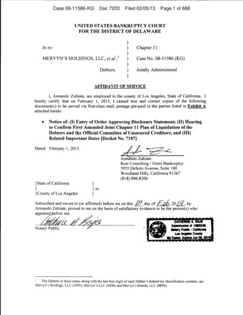
ME 24-688 – Week 11Introduction to Dynamic SimulationIntroduction to Dynamic SimulationThe purpose of this introduction to dynamic simulation project is to explorer the dynamic simulationenvironment of Autodesk Inventor Professional. This environment allows you to perform rigid bodydynamic simulations of designs. This is type of simulation is used on assemblies to simulation timevarying behavior of a system.To assist the learning of the Dynamic Simulation environment of Autodesk Inventor several key points areoutlined below and can be used for reference throughout the projects.Joint Coordinate SystemEach joint has coordinate systems that define the joint. Visually they are different from the standardAutodesk Inventor coordinate system icon. The image below shows the axis location for the symbol.There are several different joint types within Autodesk Inventor Professional. Each of the joint types havedifferent behaviors. The chart below shows each of the available joint types and some generalinformation about them.ME 24-688 – Introduction to CAD/CAE ToolsPage 1 of 31
ME 24-688 – Week 11Introduction to Dynamic SimulationStandard JointsDynamic Simulation JointsRevolutionNo TranslationD.O.F.1Rotation around the Z AxisPrismaticTranslation along the Z Axis1No RotationCylindricalTranslation along the Z Axis2Rotation around the Z AxisSphericalNo Translation3Rotation along all 3 AxisPlanarTranslation along the X and Z Axis3Rotation about the Y AxisPoint - LineTranslation along the Z axis4Rotation around all 3 AxisLine PlaneTranslation along the X and Z AxisPoint PlaneTranslation along the X and Z AxisSpatial3Rotation about the Y Axis5Rotation around all 3 AxisTranslation along all 3 Axis6Rotation about all 3 AxisWeldingNo Translation0No RotationME 24-688 – Introduction to CAD/CAE ToolsPage 2 of 31
ME 24-688 – Week 11Introduction to Dynamic SimulationRolling JointsDynamic Simulation JointsD.O.F.RI Cylinder on This allows motion between a cylinderPlaneand planeN/AThis allows motion between two primitiveRI Cylinder oncylindrical components in oppositeCylinderdirections.N/AThis allows motion between a rotatingRI Cylinder incylinder inside another non rotatingCylindercylinder.N/ARI CylinderCurveThis allows motion between a rotatingcylinder and a rotating CAM.N/AThis creates motion of two cylinders withthe same speed.N/ARI Cone onPlaneThis allows motion between a conicalface and a planar face.N/ARI Cone inConeThis allows motion of a rotating conicalcomponent within a stationary conicalcomponent.N/AThis is the same as a cylindricalcomponent but allows the user to specifypitch.N/AThis allows motion between a worm gearWorm Gear component and a helical gearcomponent.N/ABeltScrewME 24-688 – Introduction to CAD/CAE ToolsPage 3 of 31
ME 24-688 – Week 11Introduction to Dynamic SimulationSliding JointsDynamic Simulation JointsD.O.F.SI Cylinder on This allows sliding between a nonrotatingPlanecylinder and plane.N/AThis allows sliding between two primitiveSI Cylinder oncylindrical components of which oneCylindercylinder is nonrotating.N/AThis allows sliding between a nonrotatingSI Cylinder incylinder inside another nonrotatingCylindercylinder.N/ASI CylinderCurveSI Point CurveThis allows motion between a nonrotatingcylinder and a rotating cam.N/AThis creates motion of a point on onecomponent to stay on a curve.N/AAdditional JointsDynamic Simulation JointsD.O.F.2D ContactThis allows motion between the curve ofa component and the curve of anothercomponent.N/A3D ContactThis allows you to create contactbetween two components.N/AThis allows too create springs, dampers,and jacks.N/ASpring /Damper /JackME 24-688 – Introduction to CAD/CAE ToolsPage 4 of 31
ME 24-688 – Week 11Introduction to Dynamic Simulation1.1 Project 1 – Cam and Valve SimulationIn this project, you run a simulation of a cam valve assembly that has already been setup to determinethe torque required to rotate the cam to overcome the spring resistance. During the simulation you willcompare the results with friction and without friction on the rotating cam.1. Open CamValve.iam Autodesk Inventor assembly file in Autodesk Inventor.2. Click Environments tab Begin panel Dynamic Simulation. This will active the DynamicSimulation environment.3. If required, click No to close the message for beginning a tutorial.ME 24-688 – Introduction to CAD/CAE ToolsPage 5 of 31
ME 24-688 – Week 11Introduction to Dynamic Simulation4. Review the Dynamic Simulation Browser and see how the three components are listed underthe Grounded group node. Also an external load for gravity has been added in the negative YAxis direction.5. Orbit the model into a viewing position similar to the image shown below.6. Click Dynamic Simulation tab Joint panel Insert Joint to begin the process of creating astandard mechanical joint.ME 24-688 – Introduction to CAD/CAE ToolsPage 6 of 31
ME 24-688 – Week 11Introduction to Dynamic Simulation7. Select Revolution as the joint type. This will create a joint that has one (1) Degree of Freedom(DOF) allowing the parts to rotate in the Z Axis.8. For the Component 1 Z Axis selection pick the cylindrical surface on the Support part as shownbelow. Notice the origin placement by default is in the center of the cylinder.9.ME 24-688 – Introduction to CAD/CAE ToolsPage 7 of 31
ME 24-688 – Week 11Introduction to Dynamic Simulation10. Pick the Component 1 Origin select button then select the back surface as shown below for theorigin plane. This will move the joint coordinate system for the Support part back surface whilestill staying aligned to the center of the hole.11. Now select the Component 2 Z Axis selection button and pick the outer edge of the Cam part asshown below.ME 24-688 – Introduction to CAD/CAE ToolsPage 8 of 31
ME 24-688 – Week 11Introduction to Dynamic Simulation12. Notice the two joint coordinate systems that will define the joint are not aligned. The Z Axis and XAxis are pointing in different directions.13. To fix the coordinate systems alignments click the Component 2 Flip Z Axis button.ME 24-688 – Introduction to CAD/CAE ToolsPage 9 of 31
ME 24-688 – Week 11Introduction to Dynamic Simulation14. Notice now the two joint coordinate systems are aligned. This is a key element to creating jointsand one of the most important items to review as you create joints. Click OK to complete creatingthe Revolution joint.15. Now that the joint is created the two parts will snap together by aligning the coordinate systems.ME 24-688 – Introduction to CAD/CAE ToolsPage 10 of 31
ME 24-688 – Week 11Introduction to Dynamic Simulation16. Orbit the assemble into a viewing position similar to the image shown below.17. Click Dynamic Simulation tab Joint panel Insert Joint to begin the process of creating astandard mechanical joint.18. Select Prismatic as the joint type. This will create a joint that has one (1) Degree of Freedom(DOF) allowing the parts to translation along the Z Axis.ME 24-688 – Introduction to CAD/CAE ToolsPage 11 of 31
ME 24-688 – Week 11Introduction to Dynamic Simulation19. Select the Component 1 Z Axis select button and pick the bottom circular edge on the Supportpart as shown below.20. Click the Flip Z Axis button for Component 1 to align the coordinate system like the imagebelow.21. Click the select Z Axis for Component 2 and pick the bottom circular edge of the Value part asshown below.ME 24-688 – Introduction to CAD/CAE ToolsPage 12 of 31
ME 24-688 – Week 11Introduction to Dynamic Simulation22. The two coordinate systems are aligned so click OK to complete creating the joint.23. The Value part moves into position to align the two coordinate systems as shown below.24. Review the Dynamic Simulation Browser and notice the two joints that were created are nowlisted under the Standards Joints node. Also notice that the two parts that now are linked to theSupport part are listed under Mobile Groups.25. Select the Prismatic:2 joint in the Browser and Right-Click and select Properties.ME 24-688 – Introduction to CAD/CAE ToolsPage 13 of 31
ME 24-688 – Week 11Introduction to Dynamic Simulation26. Within the Prismatic:2 dialog box complete the following items to change the initial position of theValue part. Click the dof 1 (T) tab. The “T” in the tab name indicates this is translational information.Select the Edit Initial Conditions button. This will control the starting position of thecomponent.Enter 20mm as the Position valueClick OK27. Review the assembly and notice the coordinate systems for the Prismatic joint now moved apartby 20 mm.ME 24-688 – Introduction to CAD/CAE ToolsPage 14 of 31
ME 24-688 – Week 11Introduction to Dynamic Simulation28. Click Insert Joint in the Joint panel to open the Insert Joint dialog. Then select Spring /Damper / Jack for the joint type.29. This joint will allow us to create a spring object between two components. Select the bottominner circle edge of the Support part as shown below for the Component 1 selection.ME 24-688 – Introduction to CAD/CAE ToolsPage 15 of 31
ME 24-688 – Week 11Introduction to Dynamic Simulation30. Select the bottom edge of the Value part as shown below for Component 2. Click OK tocomplete creating the joint.31. Select the Spring force in the Browser and Right-Click and select Properties.32. Enter a value of 1 N/mm for the Stiffness and 50 mm for the Free Length of the spring. This willadjust the properties and size of the spring.ME 24-688 – Introduction to CAD/CAE ToolsPage 16 of 31
ME 24-688 – Week 11Introduction to Dynamic Simulation33. Click the expand button in the Spring dialog. Enter 11 mm for the Radius Dimension andclick OK to complete creating the spring.34. Notice the spring object that is now displayed to represent the joint that was created. This springwill push the Value part up into the Cam part.35. Now Double-Click on the Cam part to active the part model.ME 24-688 – Introduction to CAD/CAE ToolsPage 17 of 31
ME 24-688 – Week 11Introduction to Dynamic Simulation36. To provide a path for the Value part to contact the Cam part we will create a 2D sketch. ClickModel tab Sketch panel Create 2D Sketch to start creating a new sketch and select theWork Plane 2 that is already down the middle of the Cam part.37. With the sketch active click Sketch tab Draw panel Project Geometry. Then select the four(4) outer edges of the Cam part as shown below.38. Click Finish Sketch on the Exit panel to complete creating the sketch.39. Click Return on the Return panel to exit editing the Cam part.40. Click Dynamic Simulation tab Joint panel Insert Joint to start creating a new joint.ME 24-688 – Introduction to CAD/CAE ToolsPage 18 of 31
ME 24-688 – Week 11Introduction to Dynamic Simulation41. Select 2D Contact as the joint type.42. Select the new created sketch on the Cam part as the Curve for Loop 1 as shown below.43. Select the already existing sketch that is at the top of the Value part as shown below for Loop 2.ME 24-688 – Introduction to CAD/CAE ToolsPage 19 of 31
ME 24-688 – Week 11Introduction to Dynamic Simulation44. Click OK to complete the creation of the joint. The model will look like the image below.45. Now we will adjust the properties of the 2D contact joint. Right Click on the 2D Contact:4 joint inthe Browser and select Properties that is under the Contact Joints node. Change the Frictionvalue to be 0 and keep the Restitution value at 0.8. Keeping the Restitution value at 0.8 willmake the Value want to bounce off the Cam part during contact. Be sure that the arrows areshowing the right directions as shown above. Click invert button if necessary. Click OK tocontinue.46. Now we will setup the rotation motion on the Cam part. Select the Revolution:1 joint from theBrowser and right-click to select Properties.ME 24-688 – Introduction to CAD/CAE ToolsPage 20 of 31
ME 24-688 – Week 11Introduction to Dynamic SimulationME 24-688 – Introduction to CAD/CAE ToolsPage 21 of 31
ME 24-688 – Week 11Introduction to Dynamic Simulation47. Within the Revolution:1 dialog complete the following items: Select Edit Imposed MotionCheck the Enable Imposed Motion checkboxSelect Velocity for the Driving optionEnter 360 deg/s as the value as a Constant Value. This will make the Cam part rotate onefull time for each second of the simulation.Click OK48. On the Simulation Player, click Run or Replay the Simulation. This will cycle the simulationone time and stay at the end position.ME 24-688 – Introduction to CAD/CAE ToolsPage 22 of 31
ME 24-688 – Week 11Introduction to Dynamic Simulation49. Click the Rewind button to bring the simulation back to the initial beginning.50. Click the Run button again to watch the simulation an additional time. You will notice that thebeginning that the valve part is bouncing. We will correct this issue later in the project.51. On the Simulation Player, click Construction Mode. This will exit the run mode and allow youto make changes to the simulation.52. In the Dynamic Simulation Browser, expand Contact Joints. Right-click 2D Contact:4 (Cam:1,Valve:1). Click Properties.ME 24-688 – Introduction to CAD/CAE ToolsPage 23 of 31
ME 24-688 – Week 11Introduction to Dynamic Simulation53. In the 2D Contact:4 (Cam:1, Valve:1) dialog box, for Restitution, enter 0. Setting the Restitutionto 0 makes the contact between the two parts inelastic with no normal rebound. This value canbe set between 0 and 1 and it is a ratio of the normal velocity between the two components aftercontact. Having the setting at 1 makes it elastic so it will bounce directly off. Click OK tocontinue.54. On the Simulation Player, click Run and notice the valve part does not bounce now aftercontact.55. On the Results panel, click Output Grapher. Then under the Revolution:1 joint expand theDriving Force folder and select U imposed. This will display the Torque on the Cam rotationjoint.ME 24-688 – Introduction to CAD/CAE ToolsPage 24 of 31
ME 24-688 – Week 11Introduction to Dynamic Simulation56. Resize the Output Grapher and zoom and pan in the CamValve assembly model in the graphicswindow so you can see both.57. In the Output Grapher, double-click the dashed line at 0.25 (1). The timeline (2) is displayed, andthe cam position (3) is updated to show its position at that point of the simulation.ME 24-688 – Introduction to CAD/CAE ToolsPage 25 of 31
ME 24-688 – Week 11Introduction to Dynamic Simulation58. To cycle through the simulation, use the right and left arrow keys on the keyboard to step forwardand backward in the simulation. Cycle through the simulation to 1.00 to show the cam at the endof the simulation.59. In the Output Grapher, click Save Simulation. Save the file as CamValve.iaa. This will savethe current simulation run results to a file that can be later imported back into the OutputGrapher.60. On the Simulation Player, click Construction Mode.ME 24-688 – Introduction to CAD/CAE ToolsPage 26 of 31
ME 24-688 – Week 11Introduction to Dynamic Simulation61. The following steps describe how to add a coefficient of friction to calculate the effect on thetorque that is required to rotate the cam and overcome the spring force and friction force. In the Dynamic Simulation Browser, under Contact Joints, right-click 2D Contact:4 (Cam:1,Valve:1). Click Properties. In the 2D Contact:4 (Cam:1, Valve:1) dialog box, for Friction, enter 0.15. This enters acoefficient of friction value that will assign a force that resists the motion of the two bodies inrelation to another. The most common values range from 0 – 1 with Autodesk Inventorsupporting values from 1 – 2 also for unique cases. Click OK.62. On the Simulation Player, click Run or Replay the Simulation. The Output Grapher is stillopen, so you see the graph being generated as the simulation is running. In the next step, you change the color of the newly generated curve. When you compare thesaved graph curve with this new one, you can distinguish between the two of them.ME 24-688 – Introduction to CAD/CAE ToolsPage 27 of 31
ME 24-688 – Week 11Introduction to Dynamic Simulation63. In the Output Grapher, right-click the U imposed[1]/N mm column heading. Click CurveProperties.64. In the Dynamic Simulation - Properties dialog box, click the color box.65. In the Color dialog box, click the Red color swatch. Click OK.ME 24-688 – Introduction to CAD/CAE ToolsPage 28 of 31
ME 24-688 – Week 11Introduction to Dynamic Simulation66. In the Dynamic Simulation - Properties dialog box, click OK. The graph changes to red.67. On the Output Grapher toolbar, click Import Simulation. This will allow you to load the pastsimulation run results we saved so they can be viewed with the current results.68. In the Dynamic Simulation - Load file dialog box, select CamValve.iaa. Click Open.ME 24-688 – Introduction to CAD/CAE ToolsPage 29 of 31
ME 24-688 – Week 11Introduction to Dynamic Simulation69. Review the Dynamic Simulation Browser. The CamValve.iaa element is added to the OutputGrapher.70. In the Output Grapher, expand CamValve.iaa. Expand Revolution:1 (Support:1, Cam:1). ExpandDriving Force and select the U imposed [1] check box.ME 24-688 – Introduction to CAD/CAE ToolsPage 30 of 31
ME 24-688 – Week 11Introduction to Dynamic Simulation71. The Output Grapher displays the graphs of the torque required to rotate the cam without friction(magenta) and with friction (red). Also, a new column is added in the time-steps pane for thenumerical values of each force.Notice that the maximum torque required with friction is 200 N and without friction it is around 150N.72. Close the file. Do not save changes.ME 24-688 – Introduction to CAD/CAE ToolsPage 31 of 31
ME 24-688 – Week 11 Introduction to Dynamic Simulation ME 24-688 – Introduction to CAD/CAE Tools Page 6 of 31 4. Review the Dynamic Simulation Browser and see how the three components are listed under the Grounded group node. Also an e