Transcription
AERIAL APPARATUSOPERATIONS AND RESCUETyler Shook / David Kang
PURPOSE Not a driver / operator classUnderstand your equipmentHave a better understanding of ForcesSee apparatus through new eyesUsing the Aerial for a “high pick point” RPM / Patient Packaging review
PURPOSESo this does not happen:
RESOURCES Dr. James Burrell, Ph.D. Mission College, Santa Clara, CA 5 year study on Aerial accidents / incidents Most incidents caused by operating out of thescope of the aerial device 8 hour course Analyzed forces acting on an Aerial Apparatus
RESOURCES NFPA 1901 & 1911 Truck Company Operations Mittendorf IFSTA Fire Department Aerial Apparatus
NFPA 1901AERIAL DEVICE Consists of two or more ladder sections To reach a minimum vertical height of 50 feet. Rated at a minimum of 250 lbs.» Fully extended in a horizontal position. Full complement of ground ladders» Total 115 feet» At least 2 extension, 2 straight, and 1 attic
TYPES OF AERIALSSTRAIGHT LADDER (“STICK”)ELEVATED PLATFORM(“BOOM”)ELEVATED LADDER PLATFORM
AERIAL APPARATUS DESIGN CHASIS: Main driving unit Includes motor, breaking, electronics, etc. AERIAL: StructureMechanicsHydraulicsElectrical
AERIAL APPARATUS FAILURETHREE CAUSES OF FAILURE:1. Wear2. Abuse / Overloading3. Poor design / Manufacturing Flaw
APPARATUS STABILIZATION
CONSIDERATION #1 While operating an aerial ladder at fullextension and a 45 degree angle, the outriggerson the opposite side come off the ground. Do you continue working?
STABILITY“The truck is considered to be in a state ofstability when no sign of overturning is evidentwith the aerial ladder or elevating platform inoperation. The lifting of a tire or stabilizer onthe opposite side of the vehicle from the loaddoes not necessarily indicate a condition ofinstability. Instability occurs when an aerialdevice can no longer support a given load andoverturning is imminent.”
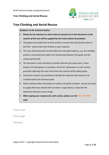
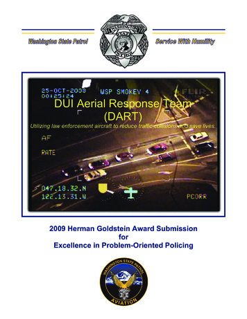
OUTRIGGER FORCE TEST2003 KME TILLER TRUCKAerial OrientationLadder beddedElevated to 75 degreesFully extended at 75 degreesRotate to 90 degrees to truckLower angle to 60 degrees45 degrees30 degrees15 degrees0 degreesWith a 200 lb load added to tip100’ (4) SECTION STRAIGHT LADDERDriver’s Side Outrigger (lbs)850088009200670026002000- Lifted0- Lifted0- Lifted0Passenger’s Side Outrigger 00
APPARATUS POSITIONING
APPARATUS POSITIONINGIt is a good practice to drivepast the incident location. Thiswill allow the truck companyofficer a look at three sides ofthe buildingConsiderations prior to spotting the ladder: Overhead hazards Collapse zones Width of the street Location of victims Height of the building
APPARATUS POSITIONINGOften spotting at the corner of thebuilding is best. Closer than collapse zone Option of two sides of the buildingIf building is on a steep incline, aposition on the downhill will maximizethe angle; a position uphill will maximizethe reach.
APPARATUS POSITIONINGElevated platforms shouldbe placed with the bottomof the platform just aboveand over the roof edge.Elevated platform railshould be placed evenwith the windowsill.Shoot above and workdown.Strait “stick” laddersshould extend past theroof-line for access fromboth sides. Roof laddersfor parapets should beused.
CONSIDERATION #2SUPPORTED V. UNSUPPORTEDSUPPORTEDUNSUPPORTED
AERIAL LOADSNFPA 1901 Dead Load: The weight of the aerial device structureand all materials, components, mechanisms, orequipment permanently fastened thereto. Live Load: Forces acting on the aerial device frompersonnel, portable equipment, water, and nozzlereaction.
AERIAL LOADS Rated Capacity: The total amount of weight of allpersonnel and equipment that can be safely supportedat the outermost rung of an aerial ladder or on theplatform of an elevating platform with the waterwayuncharged. All structural load supporting elements of the aerialdevice that are made of a ductile material shall have adesign stress of not more than 50 percent of theminimum yield strength of the material based on thecombination of the rated capacity and the dead load. 2:1 Safety Factor
AERIAL LOADS Stress: applied force to an object Strain: how the object responds How are forces applied Static (semi-static): Forces at rest or slowly applied Dynamic (shock loads): Forces in motion or quicklyapplied
CONSIDERATION #3APPLICATION OF LOADS:Force Mass X Acceleration Mass 250 lb Firefighter Acceleration 1 ft/sec (Dynamic/bouncing loads) Force 500 N/lbs On a ladder rated at 250 lbs at the tip, with a 2:1safety factor, with dynamic loads, we are at the limit.
LADDER CAPACITY CHART For ladders that arerated above 250 lbs,NFPA requires loadcharts:
AERIAL RESCUE Aerial Apparatus High Pick Point Uses: Below grade rescue» Man hole» Over-the-side High rise rescue» Roof Rescue» Window Rescue
AERIAL RESCUEHigh Pick Point Anchor Loads250 lbs250 lbs250 lbs250 lbs250 lbs500 lb Forceat the tip.250 lbs
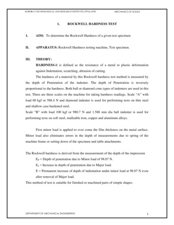
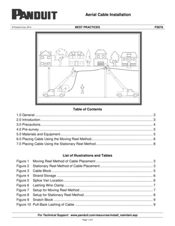
AERIAL RESCUELOAD DEGREES467 LBS427 LBS4530250 lbs250 lbs250 lbs250 lbs500 LBS250 lbs250 lbs250 lbs
HIGH PICK POINTAmerican LaFrance TDA (tractor drawn aerial) All personnel should be trained on proper roperescue techniques Apparatus operator should communicate withother crew members what the rated tip loadsare for the operating angle.
HIGH PICK POINT The aerial should only be used as a high pickpoint anchor The aerial should not be moved in anydirection during rescue operations (up/down,rotate, extend, or retract). Mandated by the manufacture and OSHA
HIGH PICK POINT Mechanical advantage should be accomplishedby rope pulled manually “Z-Rig” / “RPM” 3:1 “Ladder Rig” 2:1 4:1 - Must be positioned at 1000 lb rating
HIGH PICK POINT All riggingattempts shall bemade off the sidesof the turntablefrom 30% forwardto the cab through30 % towards tillertrailer
HIGH PICK POINTEXAMPLES OF AERIALSET UP80 FEETNIOEXTENS12 DEGREESELEVATION30 FEETELEVATIONT-6750 LB TIP LOAD ONLY(CANT USE 4TO 1 SYSTEM)
HIGH PICK POINTEXAMPLES OF AERIALSET UPIONE0F6ETESENXT18 DEGREESELEVATION30 FEETELEVATIONT-61000 LB TIP LOAD4 TO 1 SYSTEM CAN BEUSED IN THISCONFIGURATION
HIGH PICK POINTOrange webbing is used at the tip. It must be tied through both eye-letsusing a redundant loop with the knot at the bottom.
HIGH PICK POINTGrab the webbing where it comesacross between the eye-lets and bring itdown to the bottom where a carabineeris attached. Attach a high point changeof direction pulley.
HIGH PICK POINTThe next connection to make is at the bottom side of the base section ofthe aerial. This cross brace is located approximately 5 feet from the turntable. Note its location in the center of ladder (Important).
HIGH PICK POINTThis picture shows the location ofthe base section beam and the ropeinstalled on the pulleysNote the line is going straitdown the aerial
HIGH PICK POINTThis is the location of the third anchor for the third change of directionpulley. This is an orange webbing and is tied using the redundant loop
HIGH PICK POINTThis picture shows the rope location of the third change of directionpulley, note the pulley should be just outside of the fender.
HIGH PICK POINT
HIGH PICK POINTBELAY PROCEEDURES All loads, whenever possible, should be belayed. Using a TDA as a highpoint is no exception. The difference comes in forces applied in a dynamicsituation (i.e. main line failure). Even the best belayer will have some slack in the belay rope. This slack,during a main line failure, translates into force. Aerial ladders are notdesigned to handle shock loads. Whenever possible the belay should be positioned to minimize swing,pendulum and/or drop of the rescue package AND minimize or eliminateforce on the TDA.
HIGH PICK POINTBELAY exttextT-6textScenario #1: If the aerial was being used as a high point to remove a patient from the roof ofa structure the aerial’s ladder should be positioned so that, when the patient is lowered, thelitter is as close to the building as possible. The belay line should be attached to a suitableanchor on the roof of the structure and go directly over the edge of the building. In thisscenario the belay line is never attached to the aerial.
HIGH PICK POINTBELAY EScenario #2: A below grade vault, manhole, etc. Once again green is the main and red is thebelay. Again note that the belay is independent of the aerial. It is also worth noting that thepatient should only be lifted high enough to clear the hole. Once the belay is above the levelof the hole, main line failure will result in a large dynamic event.
HIGH PICK POINTBELAY PROCEEDURES When selecting any belay anchor you must remember that the load will bedynamic (falling due to main line failure). A one foot drop can magnify 5 -7 times its force on the anchor dependingon the length of the drop. Due to the angle the rope forms at the top of the aerial, the load can be ashigh as twice the load at the tip of the aerial. Due to the forces created it isrecommended that when running the belay along the aerial that the aerialshould be as closed to a climbing angle (70 degrees) as possible. Thisconfiguration loads the rams not the ladder itself.
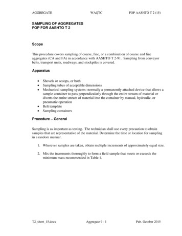
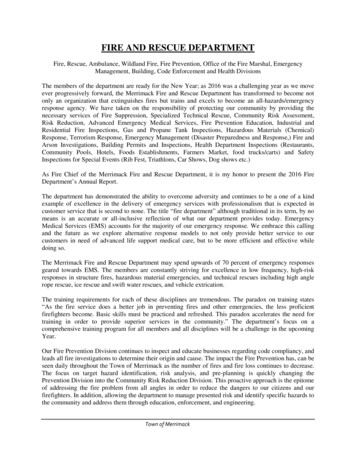
HIGH PICK POINTBELAY PROCEEDURES If there are no other options and the aerial must be used as a belay track, thebelay line should be run along the top of the aerial, over the tip, across thebuilt in rope roller and down to the load.Using the aerial as a high point belayshould be considered a last option.The forces created can easily exceedthe manufactures recommendation.Only as a last resort should the belaybe run along the aerial ladder.xtteBELAYLINEMAINLINEextt texttextT-6textBELAYLINE
Consists of two or more ladder sections To reach a minimum vertical height of 50 feet. Rated at a minimum of 250 lbs. » Fully extended in a horizontal position. Full complement of ground ladders » Total 115 feet » At least 2 extension, 2 straight, and 1 attic