Transcription
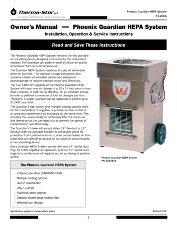
Phoenix Guardian HEPA SystemTS-265APO Box 8680 Madison, WI 53708Owner’s Manual — Phoenix Guardian HEPA SystemInstallation, Operation & Service InstructionsRead and Save These InstructionsThe Phoenix Guardian HEPA System remains the first portableair scrubbing device designed exclusively for the restorationindustry. The Guardian can perform several critical air qualityremediation functions simultaneously.The Guardian HEPA System captures virtually all removableairborne particles. The optional 4-stage absorption filtercontains a blend of activated carbon and potassiumpermanganate to remove airborne odors and chemicals.The true 1400 cfm capacity of the Phoenix Guardian HEPASystem will clean one air change of a 12 x 14 foot room in lessthan a minute. In order to be effective, an air scrubber shouldbe able to perform a minimum of four air changes per hour.Therefore, a single Guardian can be expected to control up to21,000 cubic feet.The Guardian’s high airflow and multiple ducting options allowfor the combination of negative or positive air flow control ofan area and containment air scrubbing at the same time. Thisprovides the unique ability to continually filter the indoor airand depressurize the damaged site to prevent the spread ofcontamination simultaneously.The Guardian’s intake will accept either 18” flex-duct or 12”flex-duct with the included adapter, to pressurize areas forprotection from contamination or to draw contaminated air fromareas that are difficult to access or too small to accommodatean air scrubbing device.Every Guardian HEPA System comes with one 14” lay-flat ductring, for 100% negative air operation, and two 10” lay-flat ductrings for a combination of negative air, air scrubbing or positiveairflow.Phoenix Guardian HEPA SystemPN 4024848The Phoenix Guardian HEPA System 2-Speed operation (1400-900 CFM) Multiple ducting options Built-in manometer Only 12 amps Stainless steel cabinet Optional fourth stage carbon filter Wheeled cart designRevised 1/07Specifications subject to change without notice.Toll-Free 1-800-533-7533 www.thermastor.com sales@thermastor.com
1 SpecificationsTable of ContentsIntroduction.11. Specifications.22. Operation.22.1 Transporting the Phoenix Guardian.22.2 Location.22.3 Electrical Requirements.22.4 Limiting Amp Draw.32.5 Air Ducting.32.5A Inlet Ducting.32.5B Outlet Ducting.42.6 Negative Air Ducting.52.7 Power/Speed Switch.52.8 Hour Meter.53. Maintenance .53.1 Air Filters.53.1B Carbon/Potassium Permanganate Filter.63.2 Checking Airflow.64. Service .74.1 Warranty.74.2 Blower Motor Replacement.75. Wiring Diagram.76. Service Parts List.87. Warranty.9Part No.4024848Power 12 amps, 110-120 VAC, GroundedBlower2-SpeedHigh: 1400 CFM* w/o external ductLow: 900 CFM* w/o external ductDuct Connections:Inlet: 18” diameter: 18” flex duct can be connecteddirectly to the top; 12” dia. adapter for flex ductOutlet: 10.5” square: (3) Rectangular wire-form collarsfor lay-flat plastic ducting; (1) for 14” & (2) for 10”; 12”diameter adapter for flex ductFilters:24” x 24”1-stage 1” Spun Polyester2-stage 2” Pleated Media3-stage 12” V-bank HEPA(optional) 4-stage 2” Carbon and PotassiumPermanganateWarrantyOne Year, 100% Parts and t39”45”Depth25”28”Weight 121 Lbs 155 Lbs2 OperationSerial No.2.1 Transporting the PhoenixPurchase DateThe Phoenix Guardian should be upright when transportedby vehicle. It may be tipped on to its back for loading andmoving by hand.Dealer’s Name2.2 LocationNote the following precautions when locating the PhoenixGuardian: It is designed to be used INDOORS ONLY. If used in a wet area, plug it into a GROUND FAULTINTERRUPTER. DO NOT use the Phoenix Guardian HEPA System as abench or table. It must always be used in the upright position. The air inlet on top & the front outlet should be at least1 foot from walls and other obstructions to airflow.Read the operation and maintenance instructionscarefully before using this unit. Proper adherence to theseinstructions is essential to obtain maximum benefit fromyour Phoenix Guardian HEPA System dehumidifier.2.3 Electrical RequirementsThe Phoenix Guardian can be plugged into a grounded 15Amp circuit. It draws 12 Amps or less with clean filters andno ducting (if less amperage is available, see Section 2.4).Toll-Free 1-800-533-7533 www.thermastor.com sales@thermastor.com
Due to the high percentage of a 15 Amp circuit’s capacitythat the unit uses, the circuit should be dedicated torunning the Phoenix Guardian HEPA System only. Amp drawdecreases as filters get dirty and ducting is added.CAUTION: The unit must always be operated with all threefilters and the top in place. Operating it with one or morefilters missing, the top off, and/or inferior filters will causethe amperage to increase and the motor to overload.If an extension cord is required, it must have a minimum of12 gauge conductors if 25 feet long or less and 10 gaugeconductors if greater than 25 feet long.Figure 3The 18” diameter inlet grid can be restricted by partiallycovering it with anything convenient and stiff enough tomaintain its shape (cardboard, sheet metal, plywood)The negative air pressure at the inlet will help hold therestrictor in place.2.4 Limiting Amp DrawIn certain conditions, allowing the unit to draw its normal10 to 12 Amps may be undesirable. Limited amperageavailable may be needed to run other equipment. In suchconditions, amp draw can be reduced by restricting theairflow at the inlet with the unit running on either speed.2.5 Air Ducting2.5A Inlet DuctingOccasionally the area to be filtered is difficult to accessand/or the unit cannot be located in the area. In suchcases, the air can be ducted to the unit’s inlet.A round 18” diameter flex duct can be attached to the unitinlet on top. It connects by hooking the spiral wire of theflex duct under the four tabs inside the perimeter of theinlet opening; see figures 1, 2 and 3.Flexible 18” ducting is available from Therma-Stor.An adapter is included that allows 12” flexible ducting tobe connected to the inlet. It is stored on the unit’s side.Flex duct is pushed through the adapter center with theadapter hooking tabs facing away from duct; (see figure 4).Figure 1Figure 4Figure 2Toll-Free 1-800-533-7533 www.thermastor.com sales@thermastor.com
Figure 5Figure 8Figure 6Figure 9Figure 7The spiral wire passes from one side of the adapter to theother via the notch on the hole edge; (see figure 5).The adapter and duct are positioned on the unit top withthe four tabs placed into the slots. The adapter is thentwisted counterclockwise to lock it in place; see figures 6and 7.Figure 10Toll-Free 1-800-533-7533 www.thermastor.com sales@thermastor.com
CAUTION: Exhausting too much air from a space with opencombustion devices (e.g. furnace, fireplace or water heater)can cause those devices to backdraft. This can contaminatethe space with potentially fatal gases. In such cases, thePhoenix Guardian must be used in one of the followingthree ways: (A) as a filtering unit only. Exhausting no airfrom the space and thus causing no negative pressureor backdrafting. (B) Exhausting a very limited amountof air which does not cause backdrafting. In case B, theopen combustion devices must be thoroughly checked toguarantee that they do not backdraft while the PhoenixGuardian is running. (C) direct one or more outlet ductsfrom the Guardian to the room with the open combustiondevice(s). This will positively pressurize the room, thuspreventing backdrafting. As in case B, those combustiondevices must be checked after the Guardian is running toguarantee that they are not backdrafting.Figure 112.5B Outlet DuctingThree rectangular wire-form collars are supplied that willallow round lay-flat plastic ducts to be attached to thePhoenix Guardian outlet. The two small collars are madefor 10” lay-flat duct; the large one is for 14”. Lay-flatplastic ducting is available from Therma-Stor.To attach ducting to a collar, remove the collar from theunit by loosening the two wing knobs above the collars andsliding the collar out. Put the plastic duct end through thecollar center from the front. Fold the duct end outward sothat it overlaps the outside of the collar by several inches.The same adapter that allows 12” flexible ducting to beconnected to the inlet can be used to connect 12” flexibleduct to the outlet. It is stored on the unit’s side. Flex ductis pushed through the adapter center with the adapterhooking tabs facing toward the duct, (see figure 8 and 5).One duct can be directed outside, exhausting a portionof the filtered air. The rest of the filtered air can berecirculated inside the space with or without outlet ducting.Varying the collars’ position in the guides at the outletcan control the quantity of air exhausted. To determineprecisely the amount exhausted, an airflow meter isrequired.2.7 Power/Speed SwitchThe power/speed switch is located on the unit side. Whenturned on to high or low speed, it powers the blower andhour meter.Occasionally the blower may not start on low speed. If thisoccurs, start the unit on high speed, then switch it to lowspeed.The four thumb screws that hold the two outlet collarguides must be removed; set the guides aside andreinstall the thumb screws, (see figures 9 and 10).The adapter and duct are positioned on the unit front sothe four slots in the adapter fit over the thumb screws.Rotate the adapter so the thumb screws are at the end ofthe slots and tighten the screws; see figure 11.CAUTION: Do not remove the top to access the filters withthe unit on. Removing the top and filters while running can:(A) damage the blower motor by causing it to overload, (B)expose potentially fatal high voltage electrical parts, (C)expose the dangerous rotating blower impeller.2.6 Negative Air DuctingThe Phoenix Guardian can be used to filter and exhaustair from a space. By exhausting to outside the space, thespace will be under a slight negative pressure. This willhelp prevent airborne particles from leaving the space,since the negative pressure will draw air in throughopenings in the space’s exterior.The quantity of air exhausted depends on how the unit isducted and which speed is used. One or two ducts can bedirected outside. If all the filtered air is ducted outside,this would result in up to 1300 CFM being exhausted onhigh speed and an equal amount of fresh air being drawn in.Toll-Free 1-800-533-75332.8 Hour MeterA digital hour meter is located near the power switch onthe unit side. It measures the cumulative time that the unitis turned on to tenths of an hour. It stores its total whenthe unit is unplugged. The previous total will be displayedwhen the unit is on or off. It resets to zero after 99,999.9hours of operation. www.thermastor.com sales@thermastor.com
3 Maintenancethem. This allows the operator to check the media colorthrough the top grill of the unit without removing the top.These filters are the same size as the pleated fabric filter.They are installed above that pleated fabric filter. Thepleated fabric filter catches carbon dust that comes offthese filters before it reaches the HEPA filter.The refillable carbon filter is metal-framed and can berefilled with carbon blend media purchased in 5-gallonbuckets. The amount of carbon blend media loaded intothe filter can be adjusted to the particular amount gas/odor removal required.The disposable filter contains 7½ pounds of active media.3.1 Air FiltersThe standard Phoenix Guardian is equipped with threefilters that progressively filter out smaller particles. Anoptional activated carbon/potassium permanganate filtercan be used, giving a fourth stage of filter media (seesection 3.1a). These filters must be checked regularly.Operating the unit with dirty filters will reduce the airflowand current draw, but will do no harm to the unit. The unitcan be run indefinitely with dirty filters.3.2 Checking AirflowCAUTION: The unit must always be operated with all threefilters and the top in place. Operating it with one or morefilters missing, the top off, and/or inferior filters willcause amperage to increase and may cause the motor tooverload. Permanent damage could result.An inclined tube manometer is attached to the unitto determine if the filters need replacing. It measuresnegative static pressure between the blower inlet and theHEPA filter outlet.To check airflow: Remove any inlet or outlet ducting, but leave the topand all filters in place. Make sure the unit is sittinglevel. Turn the unit on high speed for at least 15 minutes.Read the number values for the fluid levels in the upperand lower tubes. The fluid levels are slanted. Read thelevel at the center of both tubes. Subtract the lower tube number from the upper tubenumber. Match this difference to the chart on themanometer label to establish the percentage of cleanair flow.The three standard filters used are listed below (asinstalled in the unit from top to bottom):A. Polyester media pad pre-filter. Actual size is 23-3/8” x23-3/8” x 1” thick. The white side faces up. This filtershould be replaced when the airflow is reduced, it isvisibly dirty or when it is contaminated by a previousjob.B. 25 to 30% efficient (per ASHRAE 52.1-1992), MERV-7,pleated fabric filter. Actual size is 23-3/8” x 23-3/8”x 1-3/4”. This filter should be changed when airflow isreduced or it is contaminated by a previous job.C. 99.97% DOP efficient HEPA filter. Actual size is 233/8”x 23-3/8” x 12-1/2. It contains at least 175 sq.ft. of media. This filter should be changed when airflowis reduced or it is contaminated by a previous job.43100%3.1A Activated Carbon/Potassium Permanganate FiltersTwo optional gas phase filters are available from ThermaStor: a disposable and a refillable. Each uses a blendof activated carbon and potassium permanganate.This blend removes the vast majority of contaminantsencountered in most filtering applications. The activatedcarbon removes the heavier volatile organics while thepotassium permanganate removes lower molecular weightcontaminants. This is well suited to the smoke odorspresent after fire damage.The life of the media blend depends upon both the hoursused and the contamination level. Another advantageof the blended media versus activated carbon only isthat part of the blend changes color as it loads up withcontaminants. It starts out black, then turns pink, thenbrown, and finally white. It is best changed when it passesthe brown stage and begins to turn white. It has lost mostof its effectiveness at that point. When these filters areinstalled, the pad filter does not need to be installed aboveToll-Free Sample Calculation7070 6560605555505045454040353530306450% 43 100%51 90%57 80%60 70%62 60%64 50%71 - 20 51656260%252520201515101055www.thermastor.com sales@thermastor.com
4.2 Blower Motor ReplacementAirflow on high speed with all filters clean and no ductingis about 1400 CFM. The unit can be run with very dirtyfilters and virtually no flow without harming the unit. Theoperator’s decision to change filters should be based onfilter cost versus the unit’s filtering effectiveness. If airflowis 700 CFM versus 1400 CFM, the unit will filter particlesfrom a space at half the rate. The operator must judge ifthat is acceptable.If the operator determines the filters should be changeddue to low airflow, it is most economical to change them inthe following order: Change the pad pre-filter (top) first. This is the leastexpensive filter. Recheck the airflow. If the airflow isacceptable, no other filters need to be changed. Change the pleated fabric filter (middle) second. It isthe second least expensive filter. Recheck the airflow. Ifacceptable, the HEPA filter does not need changing. If the airflow is still too low, the HEPA filter must bechanged.Occasionally the blower may not start on low speed. If thisoccurs, start the unit on high speed, then switch it to lowspeed.The centrifugal blower has a PSC motor and internalthermal overload protection. Follow the steps below tochange the motor:1. Unplug the power cord.2. Remove the top and all air filters.3. Remove the wire nut that connects the blower’s whitelead to the wire harness. Disconnect the motor’s greenground wire from the unit. Remove the black and redwires from the switch.4. Remove the four nuts that fasten the blower mountingflanges to the base of the unit.5. Lift the blower out of the unit.6. Loosen the set screw that holds the impeller hub tothe motor shaft.7. Lay the blower on its side, motor up.8. Remove the 3 screws that fasten the motor supportbrackets to the blower housing.9. Lift out the motor with support brackets.10. Remove the two screws (one at each motor end) thathold the support brackets to the motor end mountingrings.11. Remove the six screws that hold the support brackethalves together. Note which holes and slots they werelocated in.12. Reassembling with the new motor is the aboveprocedure reversed4 ServiceCAUTION: Servicing the Phoenix Guardian with its highvoltage circuitry presents a health hazard that could resultin death, serious bodily injury, and/or property damage.Only qualified service people should service this unit.4.1 WarrantyA warranty certificate has been enclosed with this unit.Read it before any repair is initiated. If a warranty repairis required, call the factory first at 1-800-533-7533 forwarranty claim authorization and technical assistance.Figure 13: Electrical SchematicToll-Free 1-800-533-7533 www.thermastor.com sales@thermastor.com
5 Service PartsItemPart No.Qty.Description14023374 1Air Filter, Polyester, 1” x 24” x 24”24023375 1Air Filter, Pleated, 2” x 24” x 24”34024741 1Air Filter, HEPA, 24” x 24” x 12”(99.97% DOP)44024845 1Axle*40248162Axle Cap*40248172Axle Cap Washer* 12424972Axle Washer54023121 1Blower (Lau DD10-8A)64024813 1Cord*4024811 1Wire Harness74024073Foot284024076 1Duct Adapter, 12” Flex Duct, Inlet/Outlet940248082Duct Guide, Outlet Duct Collar1040240782Duct Outlet Collar 12” X 5.75”For 10” Lay-Flat Duct (Not Shown)11Duct Outlet Collar 12” X 10.5”4024079 1For 14” Lay-Flat Duct (Not Shown)124024810 1Handle*4024069134021597 1Hour MeterManometer Label2Handle Bracket144024867 1154024873 1Manometer Tubing164023114 1Motor, 115V,.75Hp, 1625/1180RPM(Fasco P/N 7124-2020)174023362*Nut, Plastic, ¼-20 (Not Shown)1840240833194024809 1Suspension Foam Pad (Not Shown)Snap Button204024871 1Switch, DPDT, On-Off-On2140248276Thumb Screw, ¼-20 X ½ ” Long2240248684Thumb Screw, ¼-20 X 1½” Long234024085 1Top2440250702Wheel, 10”40215912Wheel, 10” (old) shownOptional Parts402348740247644024528Air Filter, Disposable Carbon Blend2” X 24” X 24”Air Filter, Refillable Carbon Blend2” X 24” X 24”Carbon Blend, 5 Gal Pail4024750Duct, Flex, 12” X 25’4023643Duct, Flex, 18” X 25’4024935Duct, Lay Flat, 10” X 250’4024936Duct, Lay Flat, 14” X 2
Warranty One Year, 00% Parts and Labor Dimensions Machine Shipping Width 25” 29” Height 39” 45” Depth 25” 28” Weight 2 Lbs 55 Lbs 2 Operation 2.1 Transporting the Phoenix The Phoenix Guardian should be upright when transported by vehicle. It may be tipped on