Transcription
Rejuvenate Total Hip SystemSurgical ProtocolRejuvenate Modular Hip Stem Enhanced Stability1 Proven Modularity2 Intraoperative Flexibility
RejuvenateTotal Hip SystemSurgical ProtocolTable of ContentsIndications, Contraindications, & Precautions . 1System Overview . 1Preoperative Planning and X-Ray Evaluation . 2Identifying the Proximal Femoral Shaft Axis . 2Step 1 – Femoral Neck Resection. 2Step 7 – Trial Reduction Off Stem . 9Modular Stem Option Only . 9-11Step 8 – Neck and Head Implantation . 12Step 2 – Preparing The Femoral Canal . 3-4Appendix C – Modular Instrument Component Diagram . 14Step 3 – Broaching the Femur. 5Appendix D – Implant Catalog Numbers and Stem Lengths . 15Step 4 – Calcar Planing . 6Step 5 – Trial Reduction Off Broach . 6Monolithic Stem Option . 6Modular Stem Option . 7Appendix E – Offset Chart and Acceptable Head/NeckCombination Tables . 16Step 6 – Stem Implantation . 8Appendix H – Component Compatibility . 20Appendix A – Options: Modular Neck Extraction . 14Appendix B – Options: Stem Extraction . 14Appendix F – Instrument Catalog Numbers . 17Appendix G – Neck Implant Decision Algorithm . 19Surgeon Contributors:William N. Capello, M.D.Indiana University School of MedicineIndianapolis, INJoseph J. Jankiewicz, M.D.Sharps-Reely HospitalSan Diego, CALawrence G. Morawa, M.D.Oakwood HospitalDearborn, MIJames P. Crutcher, M.D.Swedish Medical CenterSeattle, WAJames Kudrna, M.D., PhDUniversity of ChicagoPritzker School of MedicineChicago, ILJoseph P. Nessler, M.D.St. Cloud HospitalSt. Cloud, MNJames A. D’Antonio, M.D.University of PittsburghPittsburgh, PA,Graham N. Gitlin, M.D.Cedars Sinai Medical CenterLos Angeles, CAKenneth A. Greene, M.D.Northeastern Ohio UniversityCollege of MedicineRootstown, OHMichael A. Masini, M.D.St. Joseph Mercy HospitalAnn Arbor, MIJoseph C. McCarthy, M.D.Massachusetts General HospitalBoston, MAPhillip O. Merritt, M.D.Glendale Adventist Medical CenterGlendale, CAJames Scott, M.D.Tifton General HospitalTifton, GABrett R. Smith, M.D.Allegheny General HospitalPittsburgh, PADaniel Ward, M.D.New England Baptist HospitalChestnut Hill, MAThis publication sets forth detailed recommended procedures for using Stryker Orthopaedics devices and instruments. It offers guidance that you should heed, but,as with any such technical guide, each surgeon must consider the particular needs of each patient and make appropriate adjustments when and as required.
Preoperative TemplatingThe Rejuvenate Femoral Platform includes a complete set of bothacetate (120% magnification) and digital femoral templates.Acetabular OptionsConditions presenting increased risk of failure include:1)uncooperative patient or patient with neurologic disorders,incapable of following instructions;Stryker offers a wide variety of acetabular components that arecompatible with the Rejuvenate Total Hip System. The surgeonshould refer to the specific acetabular component’s surgical technique for a discussion of acetabular surgical procedures.2)osteoporosis;Surgical ApproachesPatients should be warned of these contraindications and risks.Each surgeon should use the surgical approach for total hiparthroplasty with which he or she is most familiar. Patient positioning, prepping and draping, the skin incision, soft tissuedissection, and hip dislocation are performed according to thesurgeon’s preferred technique, making certain to adequatelyexpose the acetabulum and the proximal femur. The RejuvenateTotal Hip System accommodates most well-established surgicalapproaches.See the package insert for warnings, precautions, adverse effectsand other essential product information.IndicationsThe indications for use of total hip replacement prosthesesinclude:1)noninflammatory degenerative joint disease includingosteoarthritis and avascular necrosis;2)rheumatoid arthritis3)correction of functional deformity;4)revision procedures where other treatments or devices havefailed; and,5)treatment of nonunion, femoral neck and trochantericfractures of the proximal femur with head involvement thatare unmanageable using other techniques.6)Stryker’s REJUVENATE Modular Hip System is intendedfor cementless use only.Contraindications3)metabolic disorders which may impair bone formation; and,4)osteomalacia.System OverviewThe Rejuvenate Femoral Platform is a modular primary hipsystem of femoral stems and necks that provide surgeons withoptions for personalizing the implant to each patient’s anatomyand biomechanical needs. The fixation philosophy is built uponthe clinically successful Stryker hip stems. The Rejuvenatefemoral stem represents the latest evolution in the OmniFit andSecur-Fit product lines, which has a successful published clinicalhistory.3The Rejuvenate stem bodies are made of TMZF alloy, a proprietary Stryker material with a plasma sprayed coating ofcommercially pure (CP) titanium and PureFix HA. The modularnecks are made of CoCr alloy.The Rejuvenate femoral instrumentation consists of unique hipinstruments. The design of the Rejuvenate instrumentation incorporates suggestions and feedback from an esteemed panel oforthopaedic surgeons, as well as key staff members from theoperating room (OR) and central supply.The broach contours the proximal femur to the geometry of thestem to provide a complimentary fit of the stem to the bone. Thebroaches are designed with a series of teeth that are intended toseat against highly densified cancellous bone for the interferencepress-fit in the uncemented application.Absolute contraindications include:1)overt infection;2)distant foci of infections (which may cause hematogenousspread to the implant site);3)rapid disease progression as manifested by joint destructionor bone absorption apparent on roentgenogram;4)skeletally immature patients; and,5)cases where there is a loss of abductor musculature,poor bone stock, or poor skin coverage around the hip jointwhich would make the procedure unjustifiable.1
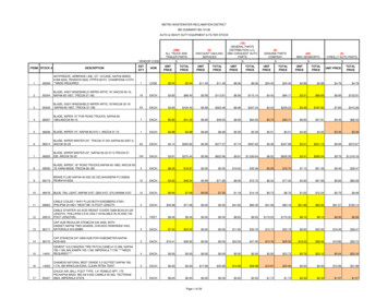
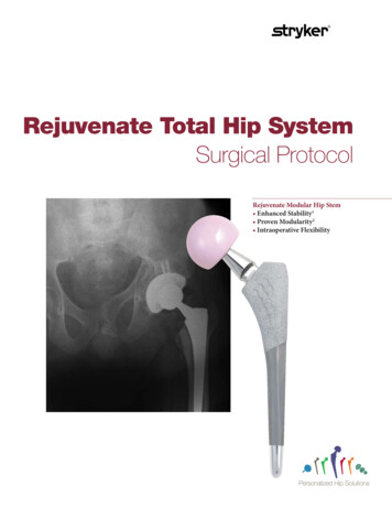
Preoperative Planning and X-Ray EvaluationPreoperative planning aids in the selection of the most favorableimplant style and size for the patient’s hip pathology. Optimalfemoral stem fit, prosthetic neck length, angle and version canbe more closely evaluated with the use of preoperative x-rayanalysis. The following parameters should be determined usingan A/P radiograph:Stem SizeFemoral OffsetLeg LengthNeck AngleCenter of Rotation1Trochanteric FossaProximalFemoralAxisDetermination of the probable implant size can facilitate operating room preparation and assure availability of an appropriatesize selection. Preoperatively, an x-ray with analysis markingscan be valuable in identifying the appropriate neck resectionlevel (see below). Anatomic anomalies that could prevent theintra-operative achievement of the established preoperativegoals may also be detected.The Pelvic Alignment Level (PAL) is an optional, single use,sterile hip position reference system that is available for useduring THR. The use of the PAL (cat. no. PAL-400) aids thesurgeon to recognize and understand the impact of intraoperative pelvic motion, and is designed to optimize acetabularalignment, reduce the chance for post-operative dislocationand restore femoral leg length and offset.2Scale onResection Guidecorresponds toscale on thetemplatesIdentifying the Proximal Femoral Shaft Axis39 Neutral alignment of a straight stem design requires the identification and preparation of the proximal femoral shaft axis. Thetrochanteric fossa, a reliable landmark for identifying the proximalshaft axis, must be unobstructed during preparation to permittrue axial reaming (Figure 1).Using theResection Guideto determineresection pointbased on lessertrochanter1 Femoral Neck ResectionLay the Stryker Femoral Resection Guide (Figure 2) on thefemur, using the lesser trochanter and the trochanteric fossa aslandmarks when making the final cut. Care should be taken toalign the axis line of the Neck Resection Guide to the center axisof the femoral shaft; the scales on the lateral flange or medialradius of the guide can be used to reference the greater or lessertrochanter respectively when making the final cut.239 Neck resection angleTipThe Resection Guide has a threaded hole in the center thatallows attachment to the modular Head and Neck Impactorshaft to facilitate use in a small operative field.
2 Preparing The Femoral Canal3Retraction of the gluteus medius and removal of a portion of themedial aspect of the greater trochanter will permit true axialintroduction of the instruments and prostheses. A Box Osteotomeis useful in removing bone from this area. Connect the BoxOsteotome attachment to the Modular Handle. Use a Mallet tostrike the end of the Modular Handle with careful controlledblows to remove remnants of the superior femoral neck andopen the medullary canal (Figure 3). Reposition the BoxOsteotome if further bone removal is desired. Disconnect theBox Osteotome attachment from the Modular Handleimmediately after use.TipA clear-out hole has been placed on the back of the BoxOsteotome that allows bone to be removed using a Curetteor other OR instruments in an action that does not requirea force to be directed at the cutting surface.4Starter ReamerThe Starter Reamer can be used to enter the femoral canalthrough the trochanteric fossa. The Starter Reamer has a pointto facilitate entry and graduated markings along the shaft thatcorrespond to implant sizes.Enter the canal with the Starter Reamer attached to either aT-handle or powered instrument. Place the Starter Reamer onthe exposed trochanteric fossa and proceed down into the shaftalong its axis to the appropriate depth. The Starter Reamershould be inserted such that the appropriate marking corresponding to the preoperatively selected stem size correlates tothe depth of the medial resection point (Figure 4).TipDepth markings on the Starter Reamer, which correspondto the Tapered Reamer depth for each stem, should bealigned with the medial aspect of the resection nt3
Trochanteric ReamingSelect and use the appropriate Trochanteric Reamer to removelateral proximal cortical bone. This will further assist in establishing proper axial alignment.5The Trochanteric Reamer is available in standard and large sizes.The Reamer should be inserted to a depth such that the distalend of the cutting flutes aligns with the medial resection point(Figure 5). Each Trochanteric Reamer is designed to prepare forthree stem sizes. See Table 1.MedialResectionPointOptionFor Sizes 4-6, the standard Trochanteric Reamer is optionaland to be used according to surgeon’s discretion.Table 1: Recommended Trochanteric Reamer SizesStem SizeTapered Reamer7-9Standard Trochanteric Reamer10 - 12Large Trochanteric Reamer6Size 7Broach Only OptionSize 8The fully toothed Broaches may facilitate preparation of thefemoral canal without the use of Tapered Reamers. However, anarrow/tight diaphyseal shaft (e.g. champagne flute femur) mayresult in broach resistance in the distal canal. If resistance isencountered, tapered reaming is recommended to minimizepotential for distal femoral fractures. If the Broach does not seatat the desired height, ream upward until the Broach seats at thedesired height. The option to skip any reaming step is at thediscretion of the surgeon. Proceed to the next page forinstructions on broaching.Tapered ReamingImplant size is determined through templating and broaching.Reamers are used to prepare the canal distally where dense corticalbone exists, thereby aiding in broaching. Ream sequentiallyupward to one size under the templated size (Figure 6).Note that although final implant size will be determined viabroaching, the last Tapered Reamer should be equal to orsmaller than the final implant. See Table 2 for a list of recommended Reamer sizes for each stem.Table 2: Recommended Tapered Reamer SizesStem SizeTapered Reamer55-665-677-887-899 - 10109 - 101111 - 121211 - 12NoteFor size 4, Starter Reamer acts as Tapered Reamer.TipIf preoperative templating results in an in-between size,ream to smaller size.4CautionReamers are sharp and aggressive.
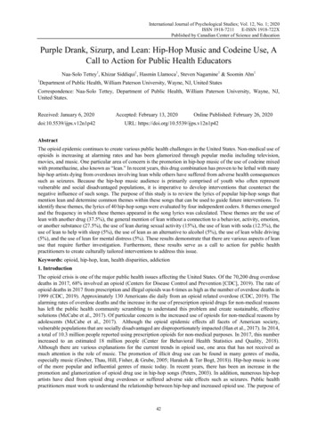
3 Broaching The Femur7Assemble the Broach to the Broach Handle by inserting thealignment tab on the distal end of the Broach Handle into theBroach (Figure 7). Closing the locking arm until an audible clickis heard secures the Broach onto the Broach Handle.Using a Mallet with short, controlled strokes, begin broachingand sequentially broach up until the desired size is reached.Throughout broaching, continue to apply lateral pressure toensure neutral alignment of the implant.QuickReleaseButtonCorrect fit will be denoted by a change in pitch or tactile resistance. To verify a secure fit, attempt to rotate the Broach relativeto the femur. With proper cortical contact, the Broach shouldnot twist or move relative to the femur. If there is movement,a larger size broach may be needed.Locking ArmLocking HookTipAlignment TabThe Stem Impactor can also be used with the Broach Handleto serve as a version guide (Figure 8). The fitting end of theStem Impactor is inserted into the top hole in the BroachHandle. The Stem Impactor can be held in place whileholding the Broach Handle. Alternately, the ModularHandle can be connected to the Stem Impactor/Version Barfitting to provide greater torsional control.Broach8The final Broach should seat tightly in the femoral canal. TheBroaches are designed to seat to the same level as the implant,allowing neck trialing to be performed directly off of the Broach.However, it may be preferable to trial directly off of theimplanted stem.The Rejuvenate Broaches and Stems are designed to produce apress-fit gradient (Figure 9). This approach to press-fit designallows for easier insertion, while enabling initial stability of thestem. Once optimal fit is achieved, remove the Broach Handleand proceed to Step 4.OptionalTrial reduction can be performed using the Broaches.However, it is recommended that for the Modular Implants,trial reduction be performed with the Modular Implant tomaximize procedure accuracy.9CautionProper insertion depth of the Broach in the canal is achievedwhen it seats tightly within the canal based on visual andauditory clues. The surgeon’s clues to firm implant fixationinclude increased pitch of sound with blows to BroachHandle and increased resistance to advancement. Relianceonly on the neck cut may lead to improper sizing, inadequate component fixation, and femoral fracture.0.125mm press-fitper sidePress-fit gradient toend of Plasma SprayregionLine to lineNoteRegular lubrication of Broach Handle is recommended.5
4 Calcar Planing10Calcar planing creates a final resection plane and angle to optimizestem fit. There are two Calcar Planers in the set (standard, large).Select the size that fits the cut surface of the neck. Each CalcarPlaner includes a spring-loaded alignment tab that providescontrolled alignment and engagement with the Broach (Figure 10).Align the tab within the Broach body, initiate power and pressdown to plane the calcar to desired level.Calcar PlanerAlignment TabNoteCalcar Planer removes less than 4mm of bone. Bone remnantscan be removed from the Calcar Planer to continue calcarplaning.11NoteNeck TrialRegular lubrication of Calcar Planers is recommended.Neck Angle132 CautionNeck Angle127 Failure to operate the Calcar Planer in accordance with theinstructions above may result in damage to the femur.Neck AngleDirectionMonolithic Stem OptionOn the inferior and superior surfaces:The neck angle marking facing superiorly represents theangle in useNeck lengthSnap the V40 Head Trial onto the Neck Trial. Perform trialreduction. After identifying the appropriate head and neck,remove the Head and Neck Trials from the Broach.ColorCodingVersionDegreesFace of Neck TrialNoteIf neck angle direction arrow points superiorly #, neck angleis 132 as shown on superior neck angle marking. If neckangle direction arrow points inferiorly , neck angle is 127 as shown on superior neck angle marking.Table 3: Monolithic Stem Neck and Head Trial ChoicesMonolithic StemMonolithic Stem GuidelinesFor body size 4, do not use femoral head offset greater than 8mm.For body size 5, do not use femoral head offset greater than 12mm.For body size 6, do not use femoral head offset greater than 12mm.Table 3 lists the permissible stem/neck and head combinations for the Monolithic Stems.Use contrary to these specifications will negate the responsibility of the device manufacturer.Broach RemovalAttach the Broach Handle to the Broach and extract using aMallet. Proceed with stem insertion and final trial reduction(See Step 6).60 127There are three monolithic Rejuvenate Stem sizes offered.Trialing is performed off the Broach with the appropriate Neckand Head Trials.Select the appropriate 0 Neck Trial, based on the pre-operativeplan and templating (refer to Table 3). The 0 Neck Trial islabeled with the following information:On the end of the trunnion:0 version degreeArrow indicating neck angle directionBlack color coding dot132 Neck Angle5 Trial Reduction Off BroachStem Size Neck AngleNeckLengthMaximumFemoralHeadOffsetMax Headand NeckCombinedLength4132 26mm 8mm34mm5132 26mm 12mm38mm6132 26mm 12mm38mm6127 30mm 12mm42mmNoteSize 6 is the only monolithic stem available with 127 neckangle.
Modular Stem OptionSelect a Neck Trial, based on the pre-operative plan andtemplating (refer to Decision Algorithm in Appendix G). TheNeck Trial is labeled with the following information:12Neck TrialNeck Angle132 On the end of the trunnion:Version degreesArrow indicating version and neck angle directionColor coding dot indicating versionNeck Angle127 On the inferior and superior surfaces:The neck angle marking facing superiorly represents the anglein useNeck lengthModular Stem - Modular Neck &Modular Head GuidelinesTotal Head & Neck Construct Length Head Offset Modular Neck Length.Table 4 below lists the permissible stem/neck and headcombinations. Appendix E lists permissible femoral headoffsets.Deviation from these specifications may affect the structuralintegrity of the neck-stem modular junction.Use contrary to these specifications will negate theresponsibility of the device manufacturer.132 Neck grees8 127Once the neck length requirements are established, select a NeckTrial with the necessary version and varus/valgus orientation thatbest reproduces patient biomechanics based on the pre-operativeplan (refer to Neck Trial Option Chart on page 11). Insert theNeck Trial into the Broach (Figure 12). The Neck Trial will snapinto place. Snap the V40 Head Trial onto the Neck Trial. Performtrial reduction. After identifying the appropriate Head and Neck,remove the Head and Neck Trials from the Broach.Neck AngleFace of Neck TrialNoteIf neck angle direction arrow points superiorly #, neck angle is132 as shown on superior neck angle marking. If neck angledirection arrow points inferiorly , neck angle is 127 asshown on superior neck angle marki
the clinically successful Stryker hip stems. The Rejuvenate femoral stem represents the latest evolution in the OmniFit and Secur-Fit product lines, which has a successful published clinical history.3 The Rejuvenate stem bodies are made of TMZF alloy,