Transcription
LBI-31960BMaintenance ManualEDACS RCN 1000TONE REMOTE CONTROLLERCAUTIONTHESE SERVICING INSTRUCTIONS ARE FOR USE BY QUALIFIED PERSONNELONLY. TO AVOID ELECTRIC SHOCK DO NOT PERFORM ANY SERVICING OTHERTHAN THAT CONTAINED IN THE OPERATING INSTRUCTIONS UNLESS YOUARE QUALIFIED TO DO SO. REFER ALL SERVICING TO QUALIFIED SERVICEPERSONNEL.ERICSSONZWARNING:TO PREVENT FIRE OR ELECTRIC SHOCK HAZARD.DO NOT EXPOSE THIS PRODUCT TO RAIN OR MOISTURE.CAUTION:TO PREVENT ELECTRIC SHOCK DO NOT USE THIS (POLARIZEDPLUG WITH AN EXTENSION CORD, RECEPTACLE OR OTHEROUTLET UNLESS THE BLADES CAN BE FULLY INSERTED TO PREVENT BLADE EXPOSUREEricsson Inc.Private Radio SystemsMountain View RoadLynchburg, Virginia 245021-800-528-7711 (Outside USA, 804-528-7711)Printed in U.S.A.
LBI-31960TABLE OF CONTENTSIMPORTANT SAFETY INSTRUCTIONS . . . . . . . . . . . . . . . . . . . . . . . . . . . . . . . . .2SPECIFICATIONS . . . . . . . . . . . . . . . . . . . . . . . . . . . . . . . . . . . . . . . . . . . . .2DESCRIPTION . . . . . . . . . . . . . . . . . . . . . . . . . . . . . . . . . . . . . . . . . . . . . . .3OPTIONS . . . . . . . . . . . . . . . . . . . . . . . . . . . . . . . . . . . . . . . . . . . . . . . . . .3INSTALLATION . . . . . . . . . . .Audio/Control Line ConnectionsDC Power Connection . . . . . .AC Power Connection . . . . . .Proper Grounding Practices . . .44444DISCUSSION OF TELEPHONE LINES . . . . . . .General . . . . . . . . . . . . . . . . . . . . . .Simple Lines . . . . . . . . . . . . . . . . . . .Types Of Voice Grade Telephone Lines . . . . .Tone Remote Controlled Systems . . . . . . . .Voting System Considerations . . . . . . . . . .Ordering Voice Grade Telephone Lines . . . . .Ordering Information For The Phone CompanyDiscussion On E & M Connections . . . . . . .444456666CIRCUIT ANALYSIS . . . . . . . . . . . . . . . . . . . . . . . . . . . . . . . . . . . . . . . . . . . .6NOTICE!This manual covers Ericsson and General Electric products manufactured and sold by Ericsson Inc.NOTICE!Repairs to this equipment should be made only by an authorized service technician or facility designated by the supplier.Any repairs, alterations or substitution of recommended parts made by the user to this equipment not approved by themanufacturer could void the user’s authority to operate the equipment in addition to the manufacturer’s warranty.NOTICE!The software contained in this device is copyrighted by Ericsson Inc. Unpublished rights are reserved under the copyrightlaws of the United States.This manual is published by Ericsson Inc., without any warranty. Improvements and changes to this manual necessitatedby typographical errors, inaccuracies of current information, or improvements to programs and/or equipment, may bemade by Ericsson Inc., at any time and without notice. Such changes will be incorporated into new editions of this manual.No part of this manual may be reproduced or transmitted in any form or by any means, electronic or mechanical, includingphotocopying and recording, for any purpose, without the express written permission of Ericsson Inc.General . . . . . . . . . . . . . . . . . . . . . . . . .Keypad/Display Board (0164) Analysis . . . . . . . .Volume Control . . . . . . . . . . . . . . . .Intercom Control . . . . . . . . . . . . . . .Clock Setting Control . . . . . . . . . . . . .Supervisory Control . . . . . . . . . . . . .Partial Speaker Mute Control . . . . . . . . .Alert Tone Control . . . . . . . . . . . . . .Clock And VU Meter . . . . . . . . . . . . .Main Board (-0167) Analysis . . . . . . . . . . . . .Voltage Regulators . . . . . . . . . . . . . .Audio Circuitry . . . . . . . . . . . . . . . .Transmit Audio . . . . . . . . . . . . . . . .Automatic Gain Control . . . . . . . . . . .Notch Filter . . . . . . . . . . . . . . . . . .Digital-To-Analog Tone Generation . . . . .Audio Tone Generation (REV. E and earlier)Audio Tone Generation (REV. F and later) . .Line Driving Amplifier . . . . . . . . . . . .Receive Audio . . . . . . . . . . . . . . . .Automatic Gain Control . . . . . . . . .Speaker Mute . . . . . . . . . . . . . .Volume Control Circuit . . . . . . . . .Earpiece Amplifier . . . . . . . . . . . .Speaker Amplifier . . . . . . . . . . . .Control Circuitry . . . . . . . . . . . . . . .Input Buffer . . . . . . . . . . . . . . . . . .Output Buffer . . . . . . . . . . . . . . . . .Watch Dog . . . . . . . . . . . . . . . . . .EPROM Control Program . . . . . . . . . .Microprocessor Control . . . . . . . . . . .Operating Mode . . . . . . . . . . . . . . . .Test Mode . . . . . . . . . . . . . . . . . . ROUBLESHOOTING . . . . . . . . . . . . . . . . . . . . . . . . . . . . . . . . . . . . . . . . . .11MAINTENANCE . . . . . .Disassembly . . . . . .Mechanical Parts . . . .Adjustments . . . . . .Installation Adjustments.OUTLINE DIAGRAMSAdjustment Locations . . . . . . . .Tone Remote Conroller(-0167)Tone Remote Parallel Option (-0171)Remote Handset Board (-0166) . . .Keypad/Display Board (-0164) . . . . . . . . . . . . . . . . . . . . . . . . . . . . . . . . . . .14. . . . . . . . . . . . . . . . . . . . . . . . . . . . . . . . . . . . . . . . . . . . . . . . . . . . . . . . . . . . . . . . . . . . . . . . . . . . . . . . . . . . . . . . . . . . . .152324Copyright November 1987, General Electric Company1
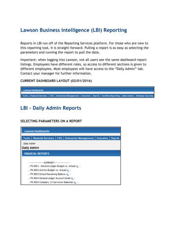
LBI-31960IMPORTANT SAFETYINSTRUCTIONShaving an equipment grounding conductor and a groundingplug. Be sure that the outlet is properly installed and groundedin accordance with all local codes and ordinances.SAVE THIS MANUAL - It contains important safety andoperating instructions for the RCN 1000 Remote Control Unit.DANGER - Never alter AC cord or plug provided. If it willnot fit outlet, have proper outlet installed by a qualified electrician. Improper connection can result in a risk of an electricshock.TABLE OF CONTENTS (Cont’d)Alternate Line/Supervisory (-0169) . . . . . . . . . . . . . . . . . . . . . . . . . . . . . . . . . .Desk Microphone (-0423) . . . . . . . . . . . . . . . . . . . . . . . . . . . . . . . . . . . . . .2628SCHEMATIC DIAGRAMSSheet 1 - Power Supply (4164-S-03) . . . . . . . . .Sheet 2 - Audio (4164-S-04) . . . . . . . . . . . . . .Sheet 3 - Digital (4164-S-01) . . . . . . . . . . . . .Sheet 4 - Parallel Option Board (4164-S-05) . . . . .Sheet 5 - Jumpers And Miscellaneous (4164-S-06) . .Remote Handset Board (-0166) . . . . . . . . . . . . . . . . .Keypad/Display Board (-0164) (4160-S-00) . . . . . . . . . .Keypad/Display Board (-0164) . . . . . . . . . . . . . . . . .Alternate Line/Supervisory Control Board (-0169)(4163-S-00)Desk Microphone (-0423) . . . . . . . . . . . . . . . . . . . .Handset (-0166)/Desk Microphone (-0423) . . . . . . . . . . .1617181920232425262829PARTS LISTTone Remote Controller Board (-0167)Parallel Option Board (-0171) . . . . .Top Housing (-4002) . . . . . . . . .Bottom Housing (-4000) . . . . . . .Wall Bracket Kit (RCZ 017) . . . . .Remote Handset Board (-0166) . . . .Handset (-4001) . . . . . . . . . . . .Keypad/Display (-0164) . . . . . . . .Supervisory/Alternate Line . . . . . .212222222223232426.Do not use auxiliary equipment not recommended or soldby the manufacturer. To do so may result in a risk of fire, electric shock, or injury to persons.To reduce risk of damage to electric plug and cord, pull byplug rather than cord when disconnecting unit.Make sure the cord is located so that it will not be steppedon, tripped over, or otherwise subjected to damage or stress.An extension cord should not be used unless absolutelynecessary. Use of improper extension cord could result in riskof a fire and electric shock. If extension cord must be used,make sure:a.that pins on plug of extension cord are the same number, size and shape as those of plug on unitb.that extension cord is properly wired and in goodelectrical condition; andc.that wire size has large enough AC ampere rating asspecified in Table 1.Table 1 - Recommended Minimum Size For Extension CordsSPECIFICATIONS *Audio OutputReceive Mode(Speaker)Transmit ModeCompression Range2550100150AWG Size of Cord181818163 watts into a 4 ohm load with less than 3% distortion 11 dBm into a 600 ohm line load (Line)With an audio increase of 30 dB beyond the start ofcompression, output level increases less than 3 dBFrequency Response 1 dB for the frequency range from 300 to 3000 HzPower Requirements110/220 Vac 20%, 50/60 Hz, 12 watts (TX), 16 watts (RX)and 10 watts (Stby)Dimensions (H x W x D)3-1/2" X 10-3/8" X 8-1/8" (Without handset holder)* These specifications are intended primarily for the use of the service technician. Refer to the appropriate SpecificationSheet for the complete specifications.WARNINGNo one should be permitted to handle any portion of the equipment that is supplied with high voltage; or to connectany external apparatus to the units while the units are supplied with power. KEEP AWAY FROM LIVE CIRCUITS.High-level RF energy in the transmitter power amplifier assembly can cause RF burns. KEEP AWAY FROM THESECIRCUITS WHEN THE TRANSMITTER IS ENERGIZED!2Length of Cord(ft)Do not operate unit with damaged cord or plug - replacethem immediately.Do not operate unit if it has received a sharp blow, beendropped, or otherwise damaged in any way; take it to a qualified service shop.Do not disassemble the unit; return it to a qualified serviceshop when service or repair is required. Incorrect reassemblymay result in a risk of electrical shock or fire.To reduce risk of electrical shock, unplug unit from outletbefore attempting any maintenance or cleaning.GROUNDING AND AC POWER CORD CONNECTION - To reduce risk of electrical shock use only a properlygrounded outlet. The unit is equipped with an electric cordThis unit is for use on a 110-volt circuit and has a grounding plug that looks like the plug illustrated in Figure 1. A temporary adapter, which looks like the adapter illustrated insketches B and C, may be used to connect this plug to a twopole receptacle as shown in sketch B if a properly groundedoutlet is not available. The temporary adapter should be usedonly until a properly grounded outlet can be installed by aqualified electrician.DANGER - Before using adapter as illustrated, be certainthat center screw of outlet plate is grounded. The green-colorrigid ear or lug extending from adapter must be connected to aproperly grounded outlet - make certain it is grounded. If necessary, replace original outlet cover plate screw with a longerscrew that will secure adapter ear or lug to outlet cover plateand make ground connection to grounded outlet.
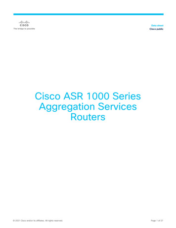
LBI-31960Table 2 - Tone Control Function And FrequencyDESCRIPTIONFUNCTIONFREQUENCY (HERTZ)CLOCK/VU METERSF11950RCZ003SUPERVISORY CONTROLSF21850RCZ004ALTERNATE LINESF31350RCZ0054 WIRE AUDIO (STANDARD)SF41250RCZ011SPEAKER MUTESF51050RCZ012INTERCOMRCZ017WALL MOUNT BRACKETRCZ021FOOTSWITCHRCZ022FOOTSWITCH W/ EARMUFFRCZ023FOOTSWITCH W/ EARPIECEHEADSETRCZ001ALERT TONERCZ002DESCRIPTIONThe RCN 1000 Remote Controller is used to control remote or remote/repeater base station radios. The RCN 1000 remote controller is housed in a specifically designed plasticenclosure to provide a modern clean design. It is available witheither a handset or desk microphone.The RCN 1000 Remote Controller utilizes audio tones inthe range from 1050 Hz to 2175 Hz. These audio tones are applied to the voice grade audio circuit that connects the remotecontroller to the termination panel. These tones are used to activate specific functions on the panel which allow the remoteoperator to control the base station radio. Each specific function tone is proceeded by a "Secur-It" tone which is a burst of2175 Hz at a level that is 10 dB higher than the function tone.The Secur-It tone must be present for 100 milliseconds beforethe panel will recognize it as valid. The function tone is thentransmitted for 40 milliseconds. See Table 2 for a listing of thefunction tone frequencies and their related functions.A "Hold" tone (2175 Hz) is transmitted at a level 20 dB below the level of the function tone, which is 30 dB below theSecur-It tone. This "Hold" tone enables the transmit functionon the appropriate frequency and holds the transmitter keyed aslong as the PTT button on the remote is pressed. When thePTT is released the 2175 Hz Hold tone is removed and thetransmission stops.OPTIONSIn addition to the variations available in the combinationnomenclature, there are other options available to the tone control versions. These versions are as follows:RCZ001Alert Tone: Permits the dispatcher to transmit analerting tone for messages of more than the usualimportance.RCZ002Clock/VU Meter: Displays time in either 12 or 24hour format, and audio level indication.RCZ003Supervisory Control: Enables the dispatcher tocomply with FCC regulations in connection withparallel remotes. Not compatible with RCZ004.Requires one switch position.RCZ004Alternate Line Selection: Allows selection of analternate line, but, does not monitor un-selectedline. Not compatible with RCZ003. Requires oneswitch position.RCZ005Four Wire Audio: Provides connections for fourwire circuits.RCZ011Partial Speaker Mute: Permits operator to reducevolume for phone calls, etc. Requires one switchposition.RCZ012Intercom: Permits intercom function betweenparalleled units without keying transmitter.RCZ017Wall Mount BracketFigure 1 - Installation DiagramOPTION3
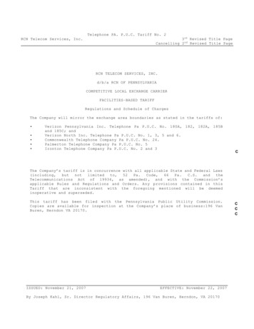
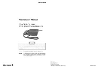
LBI-31960INSTALLATIONInstallation of the RCN 1000 involves connecting powerand ground to the controller, connecting audio/control lines,and adjustment of audio levels (some cases). Power and telephone line connection to the RCN 1000 are shown in Figure1. The four-wire path between the RCN 1000 and the remotestation panel is shown in Figure 2.PROPER GROUNDING PRACTICESA good earth ground is required to maintain surge protection on the power and audio lines. It is imperative that agood earth ground be used on the ground conductor of thepower cord. A SERIOUS SHOCK HAZARD could develop if lightning struck the control or power line. See thesafety instructions at the front of this manual.AUDIO/CONTROL LINE CONNECTIONSA standard 6-pin modular connector (J3) is used on theremote controller for telephone audio connections. A 6-wirecable is supplied with the unit for connection between J3 andthe telephone outlet. A standard 4- or 6-wire harness available from any telephone sales and service center can also beused.WARNINGDo not service this unit in the presence of a locallightning storm. Lightning may strike audio orpower lines and travel down to the unit causing serious injury. Lightning may also cause damage to internal circuits when a good earth ground is notprovided and lightning strikes audio or power lines.Table 3 - Telephone Connections To J3J3-PINWIRE COLORDISCUSSION OFTELEPHONE LINESSIGNALGENERAL1WHITENOT USED2BLACKRECEIVE AUDIO3REDTRANSMIT AUDIO4GREENTRANSMIT AUDIO5YELLOWRECEIVE AUDIO6BLUENOT USEDThis discussion covers telephone lines that are commonly used between remote control units and remotely controlled base stations.Characteristics of these voice grade lines and their application to Land Mobile communications systems will be covered. This discussion refers to frequency response only to thepoint where it affects tone signalling. It does not cover totalaudio frequency response as related to audio quality.SIMPLE LINESDC POWER CONNECTIONThe RCN 1000 may be operated from 13.8 Vdc. Connect 13.8 Vdc (nominal) to J6-2 and ground to J6-1. Maximum current drain is 0.7 amp. No battery charging isprovided by the RCN 1000. Make sure the power supply lineis adequately fused.AC POWER CONNECTIONThe RCN 1000 may be operated from a 110 Vac, 50/60Hz power source. The unit may be converted for 220 Vac operation by a qualified technician. The power plug must bechanged after the unit is converted for 220 volt operation.4In a number of cases the radio user will provide wireswithin a building or complex of buildings. Normally theseare short and involve very little loss.TYPES OF VOICE GRADE TELEPHONELINESThese lines are normally obtained from a communications common carrier ("phone company" for our purposeshere). When you ask for a voice grade (as contrasted to a"data line") telephone line you don’t know what type of lineyou will get from the phone company. Worse than that, theymay supply one type first and later change it to another typewithout telling you or the user.Figure 2 - Audio PathConnections to J3 are described in Table 3. See Figure 1for pin locations.
LBI-31960You can expect one of the following:1.Wire lines with no amplifiers.2.Wire lines with amplifiers added to compensate forline loss.3.Facilities derived from carrier (multiplex).These three types of lines are different and each must betreated differently. In large systems you may end up with allthree types of lines. In long haul applications you may end upwith two or three of these types of lines in tandem (tied together end-to-end).The first type is WIRE LINE WITH NO AMPLIFIERS.These are the same lines that you have been using for years tocontrol DC systems. These are the easiest to work with sincethey include no problem causing electronic equipment. Theseare usable on tone systems, we just don’t apply DC current tothem. You will find these lines in less populated areas wherethe phone company has not yet gone to carrier systems.These lines have a fixed amount of loss which varies withfrequency, temperature, from deterioration of splices, and frommoisture getting into the cables. When these cables get old, thephone company sometimes applies DC current to improve thejoints and lower the line loss.You are normally allowed to apply 10 dBm test tone tothese lines. These lines do not normally include any type ofvoice limiters.The second type of line is a WIRE LINE WITH AMPLIFIERS. These lines are normally supplied when the loss ofavailable lines is too high. An amplifier or several amplifiersare added to the line to make up for the loss.One commonly used amplifier is the E-6 repeater. This amplifier will pass DC current and has been used on DC lines foryears. These amplifiers include limit
Installation of the RCN 1000 involves connecting power and ground to the controller, connecting audio/control lines, and adjustment of audio levels (some cases). Power and tele-phone line connection to the RCN 1000 are shown in Figure 1. The four-wire path between the RCN