Transcription
CAPACITYOperator’s HandbookTrailer Spotting TractorWARNING!Failure to read, understand, and fully comply with the important informationcontained in this Operator’s Handbook may result in hazardous conditions orcause a hazardous condition to develop.Capacity of Texas, Inc.401 Capacity DriveLongview, TX 756041-800-323-0135
Table of ContentsSection 1. Introduction. . 11-11-21-31-4General .1Specifications. .2Major Components .3Fuel Recommendations .4Section 2. Controls & Indicators. . 5Section 3. Operation. . 173-1 Safety Precautions .173-2 Service On Reciept .183-2.1 Preliminary Service .183-2.2 Operator Orientation .183-3 Pre-Operation Inspection .193-4 Vehicle Refueling .193-5 Vehicle Start Up .203-5.1 Engine and Transmission Warmup .213-5.2 Cold Weather Starting Aids .213-6 Pre-Operation Checks .223-6.1 Proper Seat Belt Usage .223-6.2 Steering .223-6.3 Brakes and Transmission .233-6.4 Final Checks .233-7 Driving Precautions .243-8 If You Have A Problem .253-9 Engine Operation .263-9.1 Stopping the Engine .263-10 Transmission Operation .273-10.1 Pushbutton Shift Selector Operation .283-10.2 R - Reverse .293-10.3 N - Neutral .293-10.4 D - Drive .293-11 Power Take-Off (PTO) .303-12 Trailer Pickup and Movement .313-13 Trailer Spotting (Parking) .333-14 Shutdown .333-15 Towing .333-16 Dash Gauge Operation .343-16.1 Odometer Mode .343-16.2 Trip Odometer Mode .34i
Section 3. (Continued)3-16.3 Hourmeter Mode . 343-16.4 Diagnostic Mode . 34Section 4. Service & Diagnostics. . 354-1 Minor Maintenance . 354-2 Tilting the Cab . 354-3 Regular Maintenance Schedule . 364-3.1 General . 364-3.2 Daily Maintenance . 364-3.3 Weekly Maintenance . 374-3.4 Monthly Maintenance . 374-3.5 Quarterly Maintenance . 374-3.6 1000-Hour Maintenance . 384-3.7 2000-Hour Maintenance . 384-3.8 Overhead Set Adjustment . 384-3.9 Three-Year / 6000 Hour Checks . 384-4 Service Procedures . 394-4.1 Fluid Levels . 394-4.2 Engine Oil and Filter Changes . 394-4.3 Regeneration . 404-4.4 Checking Transmission Fluid Level . 424-4.5 Transmission Fluid and Filter Changes . 434-4.6 Hydraulic System Fluid . 434-4.7 Battery Service . 434-5 Diagnostics . 444-5.1 System Diagnostics . 444-5.2 Driver -Initiated Diagnostics . 444-5.3 Manual Diagnostic . 444-5.4 Fault Display . 454-5.5 Transmission Diagnostics . 914-5.6 ABS System Diagnostics . 974-6 Lubrication . 103Section 5. Specifications & Capacities. . 1055-15-25-35-45-55-65-7iiGeneral . 105TJ5000 Off Road . 105TJ5000 DOT . 106TJ6500 DOT . 106TJ7000 Off Road . 107TJ9000 Off Road . 107TJ9000 Off Road/On Road . 108
Cautions & WarningsProcedures throughout this manual contain cautions andwarnings to alert the operator to the following conditions:A warning advises the operator of conditions that may resultin damage to the vehicle, property, serious injury or possiblydeath. Pay special attention to items identified with thewarning label.A caution advises you of conditions that could result in damage to your vehicle or property.Study this manual carefully. Do not operate your vehicle untilyou are completely familiar with the contents of this manual.Always retain this manual in your vehicle for reference. If yousell the vehicle, make sure the manual goes with it.v
Safety SummaryCalifornia Proposition 65 - Diesel engine exhaust and some ofits constituents are known to the State of California to causecause cancer, birth defects, and other reproductive harm.Battery posts, terminals, and related accessories contain leadand lead components, and other chemicals known to the Stateof California to cause cancer, birth defects, and otherreproductive harm.In order to add electrical devices to your Trailer Jockey, youmust use the circuit breaker protected ignition and batterypower locations on the power distribution center (PDC).Failure to use these locations for additional electricalaccessories can result in circuit overload conditions and causeelectrical damage and/or fire in your vehicle. Failure to usethese locations for additional electrical connections will voidthe factory warranty.Before welding on any vehicle equipped with an electronicengine (ISB, ISC, QSB, QSC, CAT3126), power must bedisconnected from the engine computer. This can be done atthe battery or at the power connection to the computer on theengine. Failure to do so can result in damage to the enginecomputer and may cause engine malfunction or failure.Your Trailer Jockey has gross axle weight, gross vehicleweight, and gross combination weight ratings. Do not exceedthese ratings. Exceeding maximum weight ratings byoverloading can cause component failure resulting inpersonnel injury and property damage.vi
The Trailer Jockey is designed for efficient one-personoperation by propery trained, experienced operators. Do notallow passengers in or on the Trailer Jockey while inoperation.Reporting SafetyDefectsIf you believe that your vehicle has a defect that could cause acrash or cause injury or death, you should immediately notifythe National Highway Traffic Safety Administration (NHTSA)in addition to notifying Capacity of Texas, Inc.If the NHTSA receives similar complaints, it may open aninvestigation, and if it finds that a safety defect exists in agroup of vehicles, it may order a recall campaign. However, theNHTSA cannot become involved in individual problemsbetween you, your dealer, or Capacity of Texas, Inc.To contact the NHTSA, you may either call the Auto SafetyHotline toll free at 800-424-9393 or write to them at: NHTSA,U.S. Department of Transportation, Washington, DC 20590.You can also obtain other information about motor vehiclesafety from the Hotline or at the NHTSA website atwww.nhtsa.dot.gov.NoticeTo comply with environmental regulations limiting top speedto 25 miles per hour on industrial engines, your Trailer Jockeymay have transmission gear selections electronically inhibitedor mechanically blocked, preventing operators from shiftinginto higher gears.Restricted range selection will not affect the performance orthe warranty of the transmission. If you have any questions orrequire additional information, contact Capacity of Texas at800-323-0135.vii
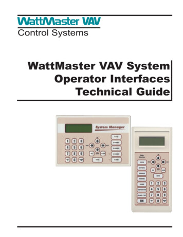
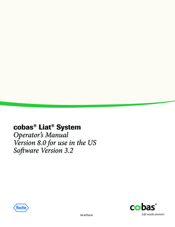
Trailer Jockey Operators HandbookSECTION 1.INTRODUCTION1-1 GENERALThis handbook contains information designed to familiarizethe operator with the controls and operation of the TrailerJockey. Be sure the operator is completely familiar with allcontrols and indicators and their functions BEFORE attempting to operate the tractor. Failure to do so could cause hazardous conditions to develop.Figure 1. Truck Dimensions1
Capacity of Texas, Inc.1-2 SPECIFICATIONS.ItemValueEnginesCummins ISB07-200 HPCummins ISB07-220 HPCummins ISLG (LNG) 250HPCummins QSBT3 6.7 L Elite 167 HPCummins QSBT3 6.7 L Elite 183 HPTransmissionAllison RDS3000Hydraulic SystemTransmission direct-mounted PTO with direct moutnedgear pump and 8-gallon (30.3 liter) reservoirFuel Tank50 gallon (189.25 liter) step tankElectrical12-Volt, negative groundcircuit breaker protectioncolor-coded wiringremovable harnessesCoolingHeavy duty fin-and-tube construction radiator filledwith 50/50 solution of permanent type antifreezeTransmission oil cooler mounted in front of radiatorAir System15.2 CFM (4.4 cmm) compressor three-tank reservoirsystemBrakesAir brakes on all wheelsParking/emergency spring-type brakes on rear wheelTractor-trailer protection valve and color-coded airlines with glad-hand bracketsWheels22.5 X 8.25 steel disc, 10-holeTires11 X 22.5, 16-ply LRH tubeless,highway treadFifth WheelLift Rating: 70,000 lbs (31,750 Kg)Lift Height: 16 in. (40.64 cm)Dimensions:Height: 120 in. (304.80 cm)Length: 186 in. (472.44 cm)Width: 95.5 in. (242.57 cm)Wheelbase: 110 in. (279.40 cm)2
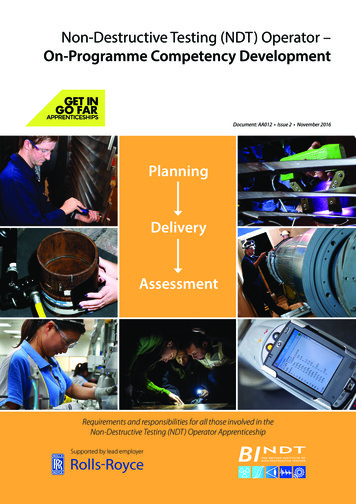
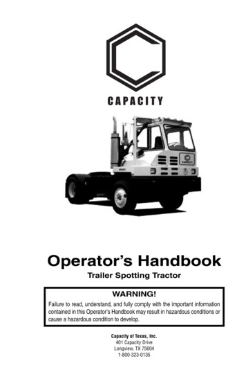
Trailer Jockey Operators Handbook1-3 MAJOR COMPONENTSFigure 2 illustrates the major components of the TrailerJockey.Figure 2. Major Components3
Capacity of Texas, Inc.1-4 FUEL RECOMMENDATIONSYour Trailer Jockey’s engine is manufactured by Cummins,Inc. To ensure optimum reliability and performance from yourvehicle, follow these recommendations regarding fuel.Due to the precise tolerances of diesel injection systems, it isextremely important that your fuel be kept clean and free ofdirt or water. Dirt or water can cause severe damage to boththe fuel pump and the fuel injectors.Lighter fuels can reduce fuel economy and possibly damagefuel system components.Cummins recommends the use of ASTM number 2D fuel foroptimum engine performance. The engine in your vehicle hasbeen optimized to meed U.S. Environmental ProtectionAgency (EPA) regulations. To meet these regulations, ultralow sulfur diesel fuel is required. If ultra-low sulfur diesel fuelis not used, the engine may not meet EPA emission regulations and damage to your engine’s aftertreatement systemmay result.Ultra-low sulfur diesel is defined by ASTM S-15 as diesel notexceeding 0.0015 (15 ppm) mass percent sulfur content. Thereis no acceptable substitute.4
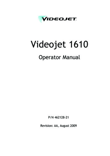
Trailer Jockey Operators HandbookSECTION 2.CONTROLS & INDICATORS2-1 INTRODUCTIONThe controls and indicators for the Trailer Jockey are illustrated on the following pages. The name and function of eachcontrol and indicator are listed in Table XREF. The indexnumbers in the figure correspond to the item numbers in thetable. The operator should know the location and function ofeach control and indicator and have a thorough knowledge oftheir functions before operating the tractor.REMEMBER!A careful operator is the best safety device!The Trailer Jockey is equipped with an operator seat belt. Theseat belt should be worn at all times during operation toprevent injury to the operator in the event of an accident.5
Capacity of Texas, Inc.Figure 2-1 Controls and Indicators.Table 2-1 Controls & IndicatorsItem6NameFunction1Status LED Panel 1Multiple LEDs indicate various conditions.Refer to Figure 2-2 for more information2TachometerIndicates engine speed in RPM
Trailer Jockey Operators HandbookTable 2-1 Controls & Indicators (Cont.)ItemNameFunction3Speedometer /Alphanumeric DisplayIndicates vehicle speed in MPH and KPH.Digital alphanumeric display belowspeedometer dial displays additionalinformation. Refer to XREF for moreinformation4Status LED Panel 2Multiple LEDs indicate various conditions.Refer to Figure 2-2 for more information5Oil Pressure GaugeIndicates engine oil pressure. Red indicatorlight indicates potentially damaging lowpressure.6Water TemperatureGaugeIndicates temperature of engine coolant inºF and ºC. Normal reading should be 180 ºFto 205 ºF.7VoltmeterIndicates voltage in electrical system. Lowvoltage may indicate problem with batteryand/or alternator.8Fuel GaugeIndicates fuel remaining in tank.9Air System PressureGauge 1Indicates pressure in air brake system inPSI and KPa. Normal reading should be10Key SwitchThree-position, key-operated switch. InOFF position, electrical system is deenergized and key can be removed. In ONposition, the electrical system is energized.In START position, starter is engaged tostart engine. Release to ON position whenengine is started.11Air System PressureGauge 2Indicates pressure in air brake system inPSI and KPa. Normal reading should be12Windshield WiperControl KnobTurns to activate variable speed wipers.Push to activate windshield washers.13Auxiliary Fan SwitchRocker switch that controls the auxiliaryfan .14Mirror Heat SwitchRocker switch that contols the outside rearview mirror heaters15LH Mirror MotorSwitchRocker switch that adjusts the left hand rearview mirror.16RH Mirror MotorSwitchRocker switch that adjusts the right handrear view mirror.17Trailer Brake LeverActivates the trailer brake.18Beacon Light SwitchRocker switch that activates the beaconlight.7
Capacity of Texas, Inc.Table 2-1 Controls & Indicators (Cont.)ItemNameFunction19Exterior Lights SwitchRocker switch that activates exterior lights20AuxiliaryRocker switch that activates auxliliarylights21Fifth Wheel FloodlightSwitchRocker switch that activates the fifth wheellight on the rear of the cab.22Cab Interior LightSwitchRocker switch that activates the interior cablights.23Headlight/Tail LightSwitchRocker switch that activates the headlightsand tail lights24Heater Control KnobRotary knob that adjusts the temperaturelevel of the cab heater.25Heater Fan ControlKnobRotary knob that sets the heater fan HIGH,LOW, or OFF26Panel Lights ControlKnobRotary knob that adjusts the brightness ofthe dash control lights.27Brake Pedal28Brake PedalPedal that controls the application of thebrakes. Depress pedal to apply brakes.Brakes should be applied slowly except inemergency situations. Trailer brakes arealso operated by the pedal if both trailer airhoses are connected.29Throttle Control PedalPedal that controls the engine throttle.Depress pedal to increase engine speed.Release pedal to reduce engine speed.Figure 2-1 Controls and Indicators (Cont.8
Trailer Jockey Operators HandbookDo not depress the fifth wheel lock pushbutton unless thetrailer is properly positioned and does not pose a threat topersonnel or property.Table 2-1 Controls & Indicators (Cont.)ItemNameFunction30Fifth Wheel LockPushbutton control that releases fifth wheellocks when pressed, releasing trailer.31Transmission ControlPushbutton control pad that controls thetransmission. Refer to Figure 2-3 fordetails.32Fifth Wheel ControlLeverThree-position control lever that positionsthe fifth wheel.LOWER - moves fifth wheel down.HOLD - Maintains fifth wheel elevationRAISE - Elevates fifth wheel33Trailer Air SupplyValvePush-pull knob that applies air pressure totrailer brake system when depressed; pullknob out to evacuate air from trailer brakesystem34Parking Brake ControlPush-pull knob that applies parking brakewhen pulled out. Depress knob to releaseparking brake.9
Capacity of Texas, Inc.Figure 2-1 Controls & Indicators (Cont.)Due to vertical motion of suspension-type seats the seatbeltset should be adjusted to allow for adequate head clearancewhen the seat is adjusted to the top of upward travel.SEAT BELTS SHOULD BE WORN AT ALL TIMES TOAVOID INJURY! ADJUST SEAT POSITION BEFOREFASTENING SEAT BELT.Table 2-1 Controls & Indicators (Cont.)Item10NameFunction35Seat Position ControlLever that is used to adjust front-to-rearposition of the seat36Seat Suspension LockLever that is used to control the seatsuspension.37Seat Back ControlKnobKnob that can be turned to adjust the tilt ofthe seat back.38Lumbar Control Switch Switch that controls the adjustment of thelumbar support39Seat HeightAdjustment SwitchSwitch that is used to adjust the height ofthe seat40Seat Belt/ShoulderHarness (not shown)See seat belt notes below
Trailer Jockey Operators HandbookFigure 2-1 Controls & Indicators (Cont.).Table 2-1 Controls & Indicators (Cont.)ItemNameFunction41ABS Diagnostic Button Pushbutton control that activates thediagnostic codes for the anti-lock brakesystem (ABS)42Engine Diagnostic /Regeneration SwitchDual-purpose switch. When engine isturned off, activates engine diagnosticmode (refer to XREF for more information.When engine is turned on, activates theengine regeneration cycle (refer to XREFfor more information).43Diagnostic ConnectorDeutsch connector that is used to connectengine diagnostic computer to truck formaintenance activities.11
Capacity of Texas, Inc.Figure 2-1 Controls & Indicators (
Operator’s Handbook Trailer Spotting Tractor Capacity of Texas, Inc. 401 Capacity Drive Longview, TX 756