Transcription
TappingGuideForPVCPressurePipeUNI-BELLPVC PIPE ASSOCIATION
TABLE OF CONTENTSPageIntroduction. 2Direct TappingGeneral . 3Equipment . 3Procedures . 5Saddle TappingGeneral . 12Equipment . 13Procedures . 15Tapping Sleeve and ValveGeneral . 17Equipment . 17Procedures . 18The statements contained in this recommended practice arethose of the Uni-Bell PVC Pipe Association and are notwarranties, nor are they intended to be warranties.Inquiries for information of specific products, their attributes and recommended uses and the manufacturer'swarranty should be directed to member companies.1
INTRODUCTIONThis booklet has been developed by the Uni-Bell PVC PipeAssociation for use as a field tapping guide. Detailed information regarding recommended procedures and equipment for tapping PVC and PVCO pressure pipe is included.The Uni-Bell PVC Pipe Association, formed in 1971, conductsresearch and development, provides technical service and support, develops recommended standards and promotes properuse of PVC pipe with gasketed joints.Its members are manufacturers who are dedicated to producinghigh quality PVC pipe products for the industry.This guide provides recommendations for tools, procedures,and acceptable pipe products for three types of taps: direct taps,saddle taps, and taps through a sleeve and valve.Note: This Tapping Guide is not intended to take the place ofthe designer's judgment. The illustrations used in this Guidedepict specific tooling for the sake of clarity. They are notintended to promote specific types of equipment or theequipment of a particular manufacturer. Other equipmentmeeting the requirements called for may be equallysatisfactory.2
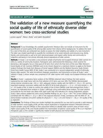
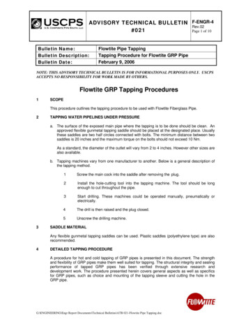
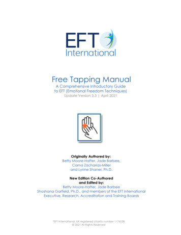
DIRECT TAPPING GENERALGENERALDIRECT TAPPING GENERALDirect tapping involves the tapping of threads into the pipe walland the insertion of a corporation stop. Direct tapping is recommended for PVC water distribution pipe manufactured in accordance with AWWA C900 in nominal sizes 6 inch through 12inch (150 mm through 300 mm) in DR 18 and DR 14.DIRECT TAPPING IS NOT RECOMMENDED FOR DR 25PIPE, NOR IS IT RECOMMENDED FOR 4 INCH DR 18 ANDDR 14 PIPE. DIRECT TAPPING IS NOT PERMITTED ON ANYSIZE OF MOLECULARLY ORIENTED (PVCO) PIPE. INTHESE CASES, SERVICE CLAMPS OR SADDLES SHOULDBE USED.EQUIPMENTA tapping machine is a mechanical device used to install the directtapped connection into water mains. The tapping machine mayvary in design and operation depending on the specificFigure 1. Components of a direct tapping machine.3
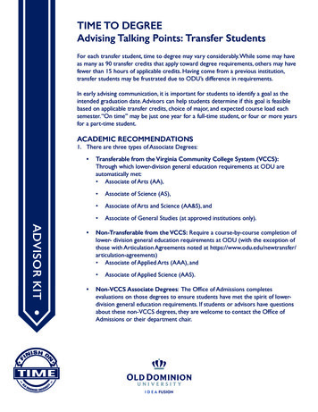
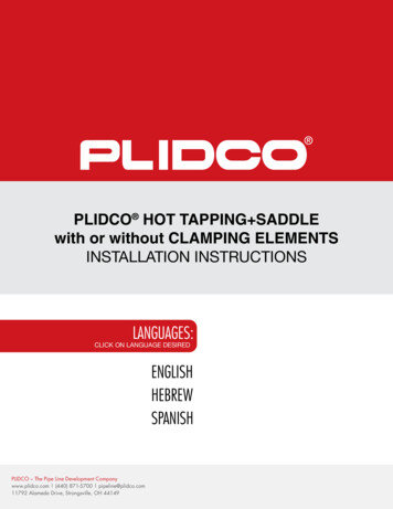
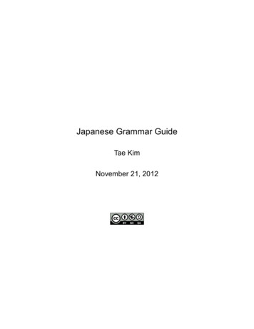
machine manufacturer. The tapping machine shall provide astandard ratchet handle on the boring bar and be of a designsuch that the cutting and tapping are controlled by a feed nutand yoke.IN NO CASE SHOULD A HAND-HELD DRILL BE USED.The machine must operate with a cutting / tapping tool suitablefor PVC pipe. This tool should be of a shell-type design, have aminimum of two slots, and shall retain the cut coupon after penetrating the PVC pipe wall.Figure 2. Combination drill and tap tool.Cutting/Tapping Tool: The combination drill and tap tool, hiFigure 2, illustrates the recommended features of the cutter. Acore drill is essential and is singularly recommended. Slottedcore drills allow an easier cut, but not a faster cut. DO NOTDRILL A HOLE IN PVC PIPE WITH A TWIST DRILL ORAUGER BIT.The core drill must retain the plug of material removed from thepipe wall (the "coupon"). A simple means of removing the coupon from the core drill should be provided. The core drill mustbe designed to accommodate walls as heavy as DR 14. Sufficient throat depth is required.4
The shank of the cutter must be adaptable to the tapping machine being used.The tap must cut AWWA C800 tapered threads. Iron pipethreads are not recommended for the pipe wall. The depth oftravel of the cutter as the threads are cut must be carefullyadjusted in order to ensure the proper insertion of thecorporation stop with 2-3 threads showing after an insertiontorque of 27-35 ft-lbs. (37 - 48 newton meters).Corporation Stop: The corporation stops should be AWWAtapered with thread complying with AWWA C800 in sizeslll5/83 and 1 inch. When sizes larger than 1 inch are required, tap/4ping saddles or sleeves should be used.PROCEDURESPlanning the Direct Tap: Only AWWA C900 DR 18 and DR 14 PVC pipes 6" (150mm) through 12" (300 mm) can be direct tapped.5 Taps up to 1-inch maximum can be made directly (i.e. /8”,3/4"and l"). Wet taps or dry taps (pipe filled or pipe empty) areallowed. Wet taps are preferred. The maximum allowable pressure in the pipe at the timethe wet tap is being completed is the rated pressure class ofthe pipe. Corporation stops must have AWWA C800 thread. Ironpipe threads are not recommended for the pipe wall.Use acombination core drill and tap when tapping direct. Recommended temperatures:—Successful tapping can be accomplished at anyootemperature in which personnel and equipment canreasonably operate.—Operators should note that PVC pipe becomes lessresistant to impact at very low temperatures. Extra care5
should be exercised in handling equipment and in cutting. At veryhigh temperatures, PVC pipe becomes more flexible, and thusmore susceptible to over-tightening of tapping machines orsaddles. Placement —Tap not closer than 24 in. (600 mm) from both the back ofoothe bell and the spigot insertion line.—Stagger multiple taps and keep them at least 18" (450 mm)ooapart lengthwise. Thus, the minimum spacing along theoosame line is 36" (900 mm).—Do not tap a curved pipe if the radius of the bend is lessoothan 300 times the pipe outside diameter.Do a test tap in the shop before starting field tapping.—Do a couple of dry bench taps to establish the mark on theooboring bar corresponding to the correct tapping depth.—Firmly seat the cutter in the holder of the tapping machine.ooSecure it well. Any wobbling or looseness of either theoocutter or the boring bar will cause problems.—Make a final check of thread compatibility. AWWA C800oothreads are required for both the tap and the corporationoostop.Observe basic tapping precautions when tapping pressurizedpipes:—Have a second worker close by.—Wear protective gear.—Provide a quick exit.—Cover the pipe area with a protective blanket (withoutooobstructing machine operation).—Follow local regulations.Bleed air from pipes at high points before tapping.Failure to vent entrapped air, while neglecting to employ atapping blanket, can create a more hazardous failure mode ifimproper tools and/or procedures are used. To maintain a safework environment, vent air from the high points, use atapping blanket, follow procedures, and use recommended6
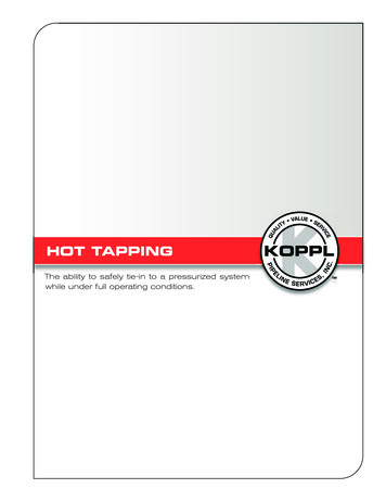
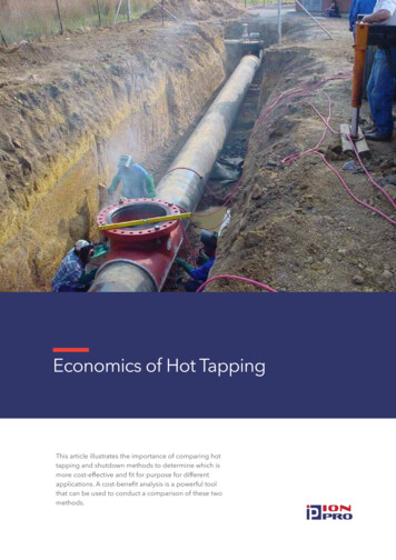
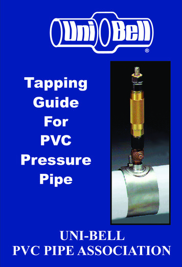
equipment.When tapping pressurized pipes, the personnel on the surfaceshould have a clear understanding of the valve operation necessaryto isolate the tapping site, if required to do so. Personnel shouldensure that the valves are operational.WRONGRIGHTFigure 3. Wrong/Left: Over tightening only one side may distort wall andstress pipe. Never use wrench extensions. Correct / Right: Both sidesevenly tightened using only the wrench supplied.Mounting the Machine: Make sure the outside diameter of thepipe (listed below) falls within the range of O.D. 's for which thetapping machine saddle is designed.Nominal Pipe Size681012Pipe O.D.6.90 in.9.05 in.11.l0 in.13.20. in.The machine should sit on the drilling site firmly, but not in away that will set up wall stresses by distorting the pipe. Theactual placement of the tapping machine on the pipe is to bedone in accordance with the recommendations of the machinemanufacturer.7
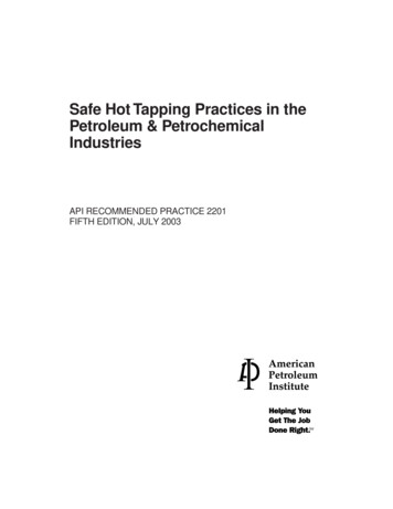
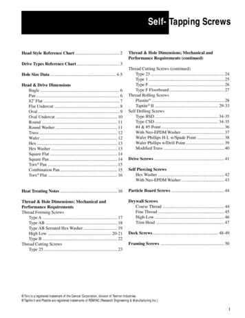
Even when taps are being made on the horizontal plane (thepreferred location because it keeps the gooseneck of the servicepipe as far below the frostline as possible) it is important that thetightening nuts be turned down evenly on each side.Follow this procedure: Adjust the nuts on the chain hooks so that they are even withthe tops of the threads. Position the chain hooks on the machine and loop the chainlinks into the hooks snugly. Tighten nuts indentified as A and B in Figure 3 alternatelyso that the same number of threads are showing when themachine is correctly and firmly mounted. During the process make sure the machine remains correctly seated in the saddle and saddle gasket. Overtightening on only one side may distort the wall and set up.Overtightening on only one side may distort the wall and set upwall stresses.Wrench extenders should not be used.CORRECTFigure 4. Feed lightly—just enough to keep the cutter engaged.Cutting the Hole and Tapping the Threads: PVC is easy tomachine. So it is a temptation to overfeed the cutter because it is8
comparatively easy to turn the ratchet handle. The principle isto allow the cutter to work as a cutter. Rotate the ratchet handleone complete turn for every one-eighth (1/8) turn of the feedyoke as shown in Figure 4.The feed rate should be less in cold weather. Judge the correctfeed rate by "finger pull"—the effort should be about the sameas used to open a desk drawer. This rule of thumb applies in anytemperature.Upon wall penetration the upward thrust on the boring bar (assuming a pressurized pipe) will be about 0.8 lb-force per 1 psiwater pressure for a 1 - inch tap.Use the feed yoke to engage the first few turns of the tappingtool in the hole. After this the tap is self-feeding and the feedyoke must be disengaged from the boring bar.The "Cast Iron" mark on the boring bar is not a reliable indicator of how deep to tap. Tapping to the correct depth is importantand should be determined by performing bench tests in advanceand carefully noting the position of the top of the threaded feedsleeve, relative to the thrust collar or other datum point, whenthe corporation stop is correctly inserted.As the tapping tool is reversed out of the hole, re-engage thefeed yoke or hold the boring bar until the tap clears the threads.Release the bar slowly so as not the damage the threads, or injure the machine operator.Examine the coupon of PVC after it is knocked out of the cutterhead. A clean edge means good cutting action. A raised crownmeans the cutter was fed through too fast.If the cutter is fed too fast, a plug of material is pushed out of theI.D. of the pipe where the tool emerges. The condition of the"coupon" provides a check of correct tapping procedure.9
WRONGRIGHTFigure 5. Wrong / Left: Rough striations indicate a dull cutter or too rapid feed.Correct / Right: Clean edges mean good cutting action.At the first sign of a "crown" on the coupons, the tapping procedure or the condition of the tools should be re-examined andcorrected before more taps are attempted. Scored edges ormelted plastic indicates a dull tool or too rapid feed. SeeFigure 5.Inserting the Stop: Attach the E-Z screw plug to the end of theboring bar. Screw the corporation stop into the E-Z releaseplug. The exposed end of the main stop will be the inlet endwith tapered (AWWA) threads. Check to BE SURE THE STOPIS CLOSED.Apply two spiral wraps of "Teflon " tape clockwise to theAWWA threads. Other thread lubricants are not recommended.Do not use liquid sealants (even though they may containTeflon).Replace the boring bar assembly in the machine and insert thestop into the main. Use care to start the first few threads in thehole so that thy are not forced or punched. Using the feed yokefor this operation requires only light finger pressure on the feednut while the ratchet handle is rotated.10
Disengage the feed yoke and remove the ratchet handle as soonas the stop has firmly engaged the threads in the pipe wall. Complete the insertion using a torque wrench.Tighten the stop to 27 foot-pounds (37 newton meters).Snap the wrench counter clockwise to release the E-Z plugfrom the shaft or boring bar assembly. Remove the tappingmachine in the usual way.If there is leaking past the threads, tighten the stop to 35 footpounds. (48 newton meters). At correct insertion, 2-3 threadsshould be visible.Remove the E-Z screw plug from the corporation stop.If leaking past the threads persists, remove pressure from theline, unscrew the main stop to clear away cuttings and replacethe stop to 27 foot-pounds. (37 newton meters), making surethe "Teflon " thread lubricant has been restored.Figure 6. Direct tapping involves the insertion of the corporation stopdirectly into the pipe wall.11
Direct Dry Tapping: When direct tapping AWWA C900 DR 18 orDR 14 PVC pipe 6"-12" that is empty, or not in service, or not yetunder pressure, the procedure given for making wet taps underpressure should be followed with a few exceptions: Remove the machine from the pipe after the hole has beendrilled and tapped. Carefully remove the cuttings from the holebefore inserting the main stop. Prepare the stop as described in "Inserting the Stop" and insertit by hand. Caution: Take special care not to crossthread thefine, "Teflon" wrapped AWWA C800 threads. Tighten the stop to the point where 2-3 threads are showing at27 foot-lbs. (37 newton meters).SADDLE TAPPINGGENERALThe use of saddles to make taps is recommended for all sizesand classes of PVC and PVCO pressure pipe. Service connections may be made using a service clamp or saddle. Maximumoutlet size recommended with service clamps or saddles is 2inches (50 mm). When making this type o
Observe basic tapping precautions when tapping pressurized pipes: —Have a second worker close by. —Wear protective gear. —Provide a quick exit. —Cover the pipe area with a protective blanket (without obstructing machine operation). —Follow local regulations. Bleed air File Size: 757KBPage Count: 23