Transcription
4 The PODS Data Model
PODS BasicsUnit 4 – A training in the PODS Data Model components andconnections
Intended Audience GIS/IT professionals New to pipeline industry Little or no exposure to PODSPODS Training – both PODS Basics and PODS Advanced – create a betterunderstanding of PODS Standards and PODS implementations throughgeospatial and relational database applications.
4 PODS BASICSAn introduction to PODS Data Modelcomponents and connections
WebinarSeriesOverview Unit 1 – PODS Basics Unit 2 - Linear Referencing Conceptsand Terms Unit 3 - PODS Data ManagementConcepts and Terms Unit 4 - The PODS Data ModelComponents and Connections Unit 5 - Spatial Analysis of Pipeline Data Unit 6 - PODS Implementation
IntroductionData ModelDatabaseTables
Our Goals for this Unit1. Visualize pipeline networks graphically using what you’ve learned about thePODS Data Model.2. Not to memorize diagram(s) you encounter, but to know how to navigate aroundthem.3. Interpret and understand this (and other) PODS model diagrams when you seethem in the future.
Data Management TermsData Model – Conceptual,logical, physicalRelational Database –Connected data tablesSchema – the physicalmanifestation of the Data Model
PODS Model Documentation LevelsConceptualModelLogicalModelPhysicalModel
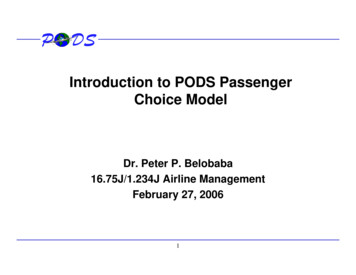
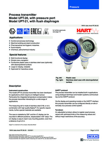
Conceptual Data ModelValveConceptualModel Low detail overview Easily understood Generalized associationsPIPELINETeeReducer
Logical Data Model More detailed model Attributes in the entitiesLogicalModel Key fields noted Database agnostic Data Rules Data Standards
Physical Data Models Entities referred to as tables Attributes are table columns Database friendly namesPhysicalModel Includes constraints and other DBcomponents Used to create DB creation scripts
PODS Organization TimelinePhysical Data Models for EACH Database TypeOne Logical ModelOne Physical Model
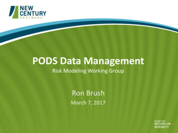
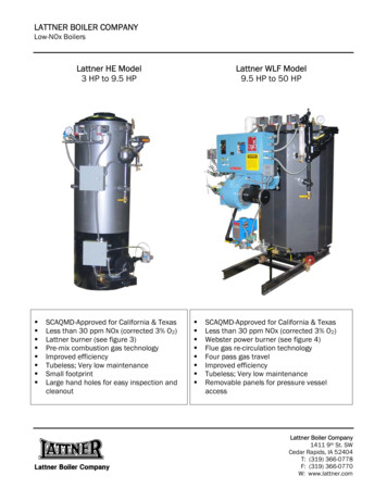
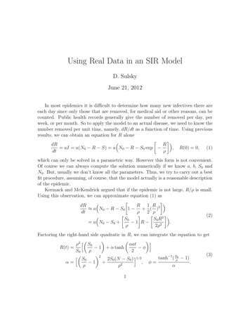
Pipeline System ModelPODS Data Model version 4.02
PODS 4.02Logical ModelMajor egulatory5.Offshore6.Offline Events
Linear Referencing ModelLocations of featuresare measured againstthe Centerline andstored in relatedtables.Spatially placed at the correctlocation along the line. How isthis represented in the 40
Table Relationships & Cardinality
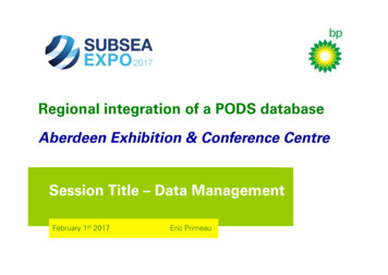
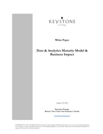
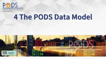
Table Relationships - Cardinality One to one One to manyA pipeline companycan operate manypipelines
Vendor Demonstration
In Summary1. There are 3 types of PODS model representations in increasing levels of detail- conceptual, logical,and physical.2. A table relationship’s cardinality specifies the number of objects in one table (Table A) that canrelate to any number of objects in a destination table (Table B).3. Cardinality types are one-to-one, one-to-many, and many-to-one.4. In a relational database model, table joins facilitate data relationships. The EVENT GUID (pk and fk)facilitates the relationship (connection) between tables. Cardinality defines that relationship.
End of Unit 4Any questions?
PODS Association web sitehttps://www.pods.orgResources forThis UnitPetro IThttps://www.petroit.us/GIS Pipeline gas-pipeline-gis-glossary-dictionary/
Pipeline System Model. PODS Data Model version 4.02. This is the PODS 4.02 Logical Model. It has been designed to hold all the information associated with a physical pipeline sys\൴em, its physical