Transcription
SERVICE TIPSEfl 2RM2453RM2552RM2553Copyright 1996 The Dometic CorporationRM2510RM2610RM2810OS1717 4/96
THE MOST COMMON SYSTEM PROBLEMS ASSOCIATED WITH THERM2310, RM2410, RM2510, RM2610 , RM2810, RM2452, RM2453, RM2552AND RM2553 REFRIGERATORSSYMPTOMNo operation.1.CAUSEOperationWiringSwitch2. No electric operation.OperationAC VoltsHeating ElementThermostatSwitchWiring3. No gas operation - no spark.OperationDC VoltsIgniterElectrodeHigh Voltage CableSwitchWiring4. No gas operation - sparks but no flame.OperationLP gasFilterOrificeBurnerShut-off ValveSafety ValveThermocoupleThermocouple Adapter,(Top Mount Controls Only)5.OperationLevelAmbient TemperatureCooling UnitNo cooling on any mode.6. No cooling on gas - cools properly on othermode(s).LP GasThermostatFilterOrificeBurnerFlue BaffleFlue Tube7. No cooling on electric - cools properly on othermode(s).AC VoltsHeating ElementThermostatSwitchWiring
SYMPTOMCAUSE8.Insufficient cooling on all modes.OperationLevelVentilationAmbient TemperatureAir LeaksThermostatCooling Unit9.Insufficient cooling on electric - coolsproperly on other mode(s).AC VoltsHeating ElementsThermostat10.Insufficient cooling on gas.Cools properly on other mode(s).LP Gas PressureThermostatFilterOrificeBurnerFlue BaffleFlue Tube11.Freezes on electric - cools properly onother mode(s).ThermostatWiring12.Freezes on gas - cools properly on othermode(s).Bypass ScrewThermostat13.Won’t stay lit on gas.LP GasSafety ValveThermocoupleThermocouple Adapter,(Top Mount Controls Only)Flame Failure Meter(Top Mount Controls Only)Flue BaffleFlue Cap (Bottom MountControls Only)OrificeBurner14.Rapid formation of frost.Food StorageAir LeaksInterior Liner Seal to FrameHigh Humidity15.No DC operation - cools properly on ACand gas.DC VoltsHeating ElementSwitchWiringRelay (RM261O/RM2810)16.Insufficient cooling on DC- cools properlyon AC and gas.DC VoltsHeating ElementRelay (RM2610/RM2810)17.RM2510/RM2610/RM2810On gas mode, sparks while flame is lit.ElectrodeLP GasBypass ScrewFilter
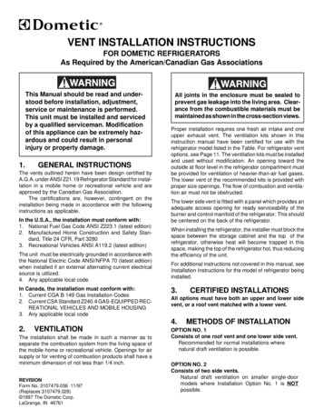
REFRIGERATORS WITH BOTTOM MOUNT CONTROLSRefrigerators with Piezo lgnitors(RM2310 & RM2410)Refrigerators with Automatic Reigniters(RM251O/RM261O/RM2610)A - ON/OFF SwitchB - Thermostat Gas/Electricc - Safety Push-buttonD - Piezo lgnitorE - Flame View PortABcE---ON/OFF SwitchThermostat, Gas/ElectricSafety Push-buttonLightGAS OPERATIONRefrigerators with Piezo lgnitor (RM2310 & RM2410)To start the refrigerator, turn knob “A” to the “GAS” position.Turn the thermostat knob “B” one-quarter (l/4) of a turn from the “OFF” position.Push button “C” in until it bottoms out-and hold. While holding button “C”, push button “D” for thepiezo ignitor several times to light the burner. This can be observed through the flame view port, “E”,on the refrigerator.After the flame lights, continue to hold button “C” for an additional fifteen (15) seconds. Release thebutton “C” and check the flame view port “E” to make sure the burner does not go out. If the burnergoes out, repeat the lighting procedure.To shut off the refrigerator, turn Knob “A” to the “OFF” position.Refrigerators with Automatic Reigniters (RM2510/RM2610 /RM2810)To start the refrigerator, turn knob “A” to the “GAS” position.Turn the thermostat knob “6” one-quarter (l/4) of a turn from the “OFF” position.Push button “C” in until it bottoms out-and hold. When lamp “E” stops flashing, hold push-button “C”an additional 15 seconds. Release button “C”. If the lamp “E” starts to flash again, repeat lightingprocedure. If flame blows out, the reigniter will automatically relight the flame.4
NOTE: After changing an LP tank, or after a long shut off period, the gas line is likely to be filledwith air. You may have to repeat the lighting procedure several times to purge the air out of thegas lines.ELECTRIC OPERATIONCheck to be sure the power cord is properly connected to the power supply. If the refrigerator isequipped for 12 volt DC operation, the tow vehicle engine should be running to prevent dischargingthe battery.Turn knob “A” to the position marked “ELEC” for 120 volt AC operation or “12V” for 12 volt DCoperation.Turn the thermostat knob “B” one-quarter (l/4) of a turn from the “OFF” position.To shut off the refrigerator, turn knob “A” to the “OFF” position.THERMOSTATThe refrigerator is equipped with a thermostat that can be adjusted by turning knob “B” to a differentsetting to maintain the desired cabinet temperature.“OFF” Setting of the Thermostat: In gas operation, the thermostat closes its main valve and theburner runs continuously at the bypass rate or pilot. In electrical operation, the contacts in the thermostat are open and the heating elements are off.“MAX” Setting of the Thermostat: In gas operation, the thermostat allows the burner to remain onhigh flame continuously. In electric operation, the heating element is “ON” continuously.The thermostat can be adjusted between “MAX” and “OFF” to obtain the desired cabinet temperature. The closer the knob is to “MAX”, the colder the cabinet temperature. The closer the knob is to“OFF”, the warmer the cabinet temperature.When the thermostat reaches the set temperature, it will cut the burner back to bypass or, in electricoperation, shut off the heating element.
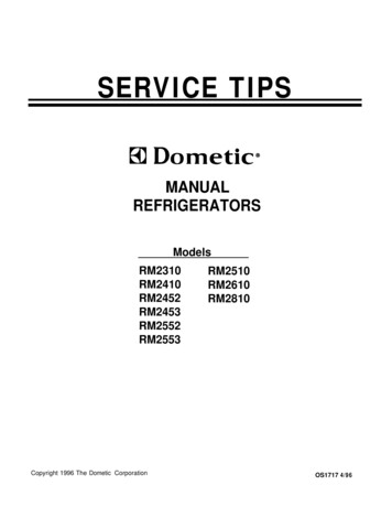
OPERATIONREFRIGERATORS WITH TOP MOUNT CONTROLSREFRIGERATORS WITHPIEZO IGNITORS:RM2452 AND RM2453LEGEND:A Energy Selector KnobB Thermostat KnobC Flame Failure SafetyValve Push ButtonD Piezo lgnitorE Flame Indicator--- - -----m-------------v-REFRIGERATORS WITHAUTOMATIC IGNITION:RM2552 AND RM2553
GAS OPERATIONREFRIGERATORS WITH PIEZO IGNITOR(RM2452 & RM2453)1. To start the refrigerator, turn knob “A” to the “GAS” position.2. Turn the thermostat knob “B” one-quarter (1/4) of a turn from the “OFF” position.3. Push button “C”, push button “D” for the piezo ignitor several times to light the burner. This can be observedon the flame indicator “E”, on the refrigerator.4. After the flame lights, continue to hold button “C” for an additional ten (10) seconds. Release the button “C” andcheck the flame indicator “E” to make sure the burner does not go out. If the burner goes out, repeat the lightingprocedure.5. To shut off the refrigerator, turn knob “A” to the “OFF” position.REFRIGERATORS WITH AUTOMATIC REIGNITERS(RM2552 AND RM2553)1. To start the refrigerator, turn knob “A” to the “GAS” position.2. Turn the thermostat knob “B” one-quarter (l/4) of a turn from the “OFF” position.3. Push button “C” in until it bottoms out - and hold. When flame indicator “E” shows the flame is on, hold pushbutton “C” an additional 15 seconds. Release button “C”. If the flame indicator “E” starts to move toward off,repeat lighting procedure. Should flame blow out, the reigniter will automatically relight the flame.NOTE: After changing an LP tank, or after a long shut-off period, the gas line is likely to be filled with air. Youmay have to repeat the lighting procedure several times to purge the air out of the gas lines.ELECTRIC OPERATIONCheck to be sure the power cord is properly connected to the power supply. If the refrigerator is equipped for 12volt DC operation, the tow vehicle or caravan engine should be running to prevent discharging the battery.Turn knob “A” to the position marked “ELEC” for 120 volt AC operation or “12V” for 12 volt DC operation.Turn the thermostat knob “9” one-quarter (l/4) of a turn from the “OFF” position.To shut off the refrigerator, turn knob “A” to the “OFF” position.THERMOSTATThe refrigerator is equipped with a thermostat that can be adjusted by turning knob “9” to a different setting to maintainthe desired cabinet temperature.“OFF” Setting of the Thermostat: In gas operation, the thermostat closes its main valve and the burner runscontinuously at the bypass rate or pilot. In electrical operation, the contacts in the thermostat are open and theheating elements are off.“MAX” Setting of the Thermostat: In gas operation, the thermostat allows the burner to remain on high flamecontinuously. In electric operation, the heating element is “ON” continuously.The thermostat can be adjusted between “MAX” and “OFF” to obtain the desired cabinet temperature. The closerthe knob is to “MAX”, the colder the cabinet temperature. The closer the knob is to “OFF”, the warmer the cabinettemperature.When the thermostat reaches the set temperature, it will cut the burner back to bypass or, in electric operation, shutoff the heating element.The setting of the thermostat is not critical, but we recommend it be adjusted to maintain a dry frost on the cooling fins.Adjust the thermostat knob closer to “MAX” when the outside temperature becomes warm.
AC VOLTAGE REQUIREMENTSThe proper operating range is 100 to 132 volts. Check the AC volts at the receptacle where the refrigerator is attached.If voltage drops below 100 volts, cooling efficiency will decrease with voltage decrease.AC COMPONENTSHEATING ELEMENTTo check a heating element, remove the heater leads from the terminal blockand measure for proper resistance across the two leads.You should obtain the following readings, plus or minus 10%:RM2310 92RM2410 92RM2510 7 5RM2610 48RM2810 44RM2452 69RM2453 69RM2552 69RM2553 69DC VOLTAGE REQUIREMENTSThe operational range is 10.5 to 15 volts DC. Check for proper voltage at the terminal block or blocks at the back ofthe refrigerator. The power supply to the refrigerator must be fused.DC COMPONENTSSWITCH (BOTTOM MOUNT CONTROLS)A. Remove all wires from the assembly.For the DC mode, continuity should exist between terminals 1 and 1A and 2 and2A. (3-Way Models Only)For the AC mode, you should have continuity between 4L and 4A and 5N and 5A.RM2310 & RM2410 SWITCH ASSEMBLYDC ModeDC ModeAC ModeAC -Mode
B. The RM251O/RM261O/RM2810 selector switch should be checked for continuity in the following manner. Removeall wires from the assembly.For the DC mode, continuity should exist between terminals 1 and IA and2 and 2A. For the gas mode, you shouldhave continuity between 3 and 3A.For the AC mode, you should have continuity between 4L and 4A and 5N and 5A.RM251O/RM261O/RM2810 SWITCH ASSEMBLYGas ModeDC Mode \ AC ModeDC ModeAC ModeGas ModeSWITCH (TOP MOUNT CONTROLS)Remove all wires from the assembly.For the DC Mode (3-Way Models ONLY), continuity should exist between terminals 5 and 5a and 6 and 6a.For the AC Mode, continuity should exist between terminals 1 and la and 2 and 2a.For the Gas Mode (on refrigerators equipped with automatic REIGNITERS ONLY), continuity should exist betweenterminals 4 and 4a.RM2452/RM2453/RM2552/RM2553 SWITCHGas ModeACMode 1‘DC ModeGas Mode
IGNITERA. MODEL RM2310,2410,2452,2453When the button is pushed, a spring loaded striker creates a spark. If there is no resistance when pressing the button,the piezo igniter is defective.B. MODEL RM2510,2610,2810,2552,2553Check that the switch is in the gas mode and is completing the circuit. Next, verify proper voltage at the positive ( )and ground (-) terminals of the igniter. The reading should be within one volt of incoming voltage at the terminal block.HIGH VOLTAGEDisconnect DC power at the terminal block. Remove high voltage cable from igniter. Reconnect DC power, the ignitershould produce a sparking sound.ON MODEL RM2510,2610 AND 2810: With the igniter producing spark, set the meter on 20 volts DC or lower scale,connect meter leads to L and ground terminals on the igniter. The meter should read a pulsating voltage.The pulsating voltage allows a lamp to illuminate on the front of the refrigerator to advise the customer spark has beenproduced.ELECTRODEDo a visual inspection for cracks or breaks on the ceramic insulator. Also, verify the mounting bracket is attachedproperly to the electrode. Check the spark gap. It must be set at three sixteenths (3/16) of an inch and the tip ofelectrode above the slots in the burner.ELECTRODETlP10
HIGH VOLTAGE CABLEBe sure switch and igniter are good before checking the high voltage cable and the switch is in the gas mode.Disconnect DC power at the terminal block. Disconnect high voltage cable from electrode. Reconnect DC power tothe terminal block. If sparking starts, cable is good. If no sparking, disconnect DC power at the terminal block and thendisconnect high voltage cable at the igniter. Reconnect DC power to the terminal block.RELAY (RM261 0/RM2810 3-WAYMODELS ONLY)Verify the selector switch is on DC mode and the thermostat is NOT completing thecircuit. Verify voltage is present between terminals 85 and 30. Check for voltage between terminals 85 and 87. If voltage is present, the relay isdefective.Verify the selector switch is on DC mode and the thermostat is completing the circuit.Verify voltage is present between terminals 85 and 86.If voltage is present, between 85 and 86 terminals, then voltage should be present betweenterminals 85 and 87.A11
HEATING ELEMENT(3-WAY MODELS ONLY)Check the heating element with ohms resistance using a properly calibrated ohm meter.You should obtain the following readings, plus or minus 10%:1.15 OHMSRM23101.15 OHMSRM2410.82 OHMSRM2510.67 OHMSRM2610RM2810.67 OHMSRM2453.83 OHMSRM2553.83 OHMSA continuity reading will indicate an open or complete circuit.FLAME INDICATOR METERIf the millivolts from the thermocouple are 5 millivolts or more, the red needle in the meter should be in the green section.LP GAS REQUIREMENTSThe LP gas pressure to the refrigerator should be 11 inches watercolumn with half of all BTU’s of the RV turned on. With all otherappliances turned off, the pressure to the refrigerator should notexceed 12 inches water column. To check the gas pressure whenthe refrigerator is operating, there is a pressure test housinglocated just prior to the orifice.- -*‘PRESSURE TEST HOUSINGLP GAS COMPONENTSREFRIGERATORS WITHBOTTOM MOUNTCONTROLSSHUT-OFF VALVETo check the shut-off valve, remove and inspectfor any obstructions.MANUAL GAS SHUTOFF VALVEREFRIGERATORS WITH TOP MOUNT CONTROLS/MANUALGAS VALVEMANUALGAS VALVE12
FILTERA filter is located in the inlet fitting to the thermostat. The filter can become saturated and cause a restriction to gasflow. If you suspect a restriction, first verify the thermostat and bypass screw are good.THERMOSTATLP GAS MODEThe thermostat is calibrated by the manufacturer so that at mid-range the cabinet temperature should beapproximately 40 degrees Fahrenheit. To check the calibration of the thermostat, place a container of water in thecabinet of the refrigerator and operate at mid-range setting until the thermostat is satisfied. Check the temperatureof the water. It should be approximately40 degrees. To check the thermostat for proper g a s flow, set the thermostatto maximum and check the gas pressure at the pressure test port. It should be line pressure, between 11 to 12 incheswater column. If you have less than 11 inches of water column pressure, the next step would be to shut off the gassupply and remove the bypass screw. Then install a bypass screw that does not have the small o-ring on it. Next, turnon the gas supply and take a reading. If the manometer now reads 11 inches of water column, the thermostat isdefective and must be replaced. If the bypass screw test shows no change in pressure, the problem lies in the filter,the shut-off valve or the gas supply.ELECTRIC MODEOn 2-way models it controls the AC heating element. On 3-way models it controls the DC heating element as well asthe AC heating element. Check the thermostat for continuity.BYPASS SCREWThere are three common sizes of this screw: S-17 (350 BTU), S-14 (325 BTU) and S-l 1 (300 BTU). To check thebypass screw, connect a manometer at the pressure test housing. The pressure on low flame mode should be 2 to4 inches water column.SAFETY VALVETo check the safety valve, use a known good thermocouple and install into the safety valve. Supply flame to the tipof the thermocouple for 2 to 3 minutes while holding in on the safety valve stem. Remove flame from thermocoupletip and release safety valve stem. The safety valve should hold in for at least 30 seconds.THERMOCOUPLEIt will produce 14 to 30 millivolts DC in normal operation. To check the thermocouple, use a known good safety valveand attach to the thermocouple. Next, supply flame to the tip of the thermocouple for 2 to 3 minutes while depressingthe safety valve. Remove the flame and release the safety valve. The valve should hold for at least 30 seconds. If itdoes not hold the safety valve open for 30 seconds.THERMOCOUPLE ADAPTERThe thermocouple adapter is a device that allows the flame indicator meter to read DC millivolts from the thermocouple.Remove it from its location and do a continuity test from the terminal to the center post. Continuity should exist. Next,check for continuity between the terminal and casing. No continuity should exist.BURNERIt should be level and the slots in the burner should be directly below the flue tube. The burner should be cleanedperiodically, at least once a year.FLUE BAFFLEIt should be cleaned periodically, at least once a year.FLUE CAP - BOTTOM MOUNT CONTROLSIt must be properly attached or flame outage could occur.13
hElllV8n”hm11v8nI--- ’ESSZW /Ol8ZW /Ol9ZWtl/OlSZWtlIO GU!YJOM SJB noA lapow all1 Jo! WeJfhp BU!J!M ayi Jad paJ! s! Jote aQJla aqt ,QJ AsJow7puo3 0 au140 Jaql!a 04 alrylsqnsse ap!qaA au1 40 s!ssey3 Jo Apoq aut asn lou oaDNltllM lVNU31NI‘kEllV3H l-IO/\ 3Cl P lJ’ ’y3Olq leU!UJJal aY101 apeW S! UO! 3aUUO3 S!ql :(@lO*a3a SIlOA Zl PayJEW y3Olq Il?U!WJal ayl 01 E E?lUS! uoy3auuo3 aq1 :p‘3WPWI AeM-E) Jd-6nld s!ql WOJ 6uoJd 6u!-pUnOJ6 aql aAOUJaJ JOln3lON oa *al3sldaceJ 6uoJdaalyl papunoJ6 AlJadoJd e og I(l )a !p pa66nlda q PlnOyS pue SpJEZZEq y3oys J!F?BB UO!palOJd 04 6nld (papunoJ6) 6UOJd-aaJqi t? L&M paddgbaS! JOleJa6!JjaJ aql :UO! tX3UuO 3v Sllon ()zc ‘VDNltllM lVNt131X3SlEl13W1133d NIHItIN 3UlM 013flClN03 -IV101 HZSPZIW8S#0 18ZWklE9#0 19ZNtlEP#OlciZWki6E#OCPZWtl66#OCGZWtl:SMOllOl SE!S! JOlE?Jatj!J4aJ l nlEUJ EN.# JOi aD!l!JO SZ!S I3SJJO3 C3L(l *Jeah I2 XXI0 ISt?t3l ? ‘I(llw!po!Jad palEal aq PlnOqS Xl!4!JO ayl33Ult10*leaA e aDuo y t?al 112 ‘&xNpo!Jad paueal3 aq w-cu 138fll3fll
TYPICAL 2-WAY WITH PIEZO IGNITERFOR REFRIGERATORS WITH BOTTOM MOUNT CONTROLS1123 VOLTS ACTYPICAL 3-WAY WITH PIEZO IGNITERFOR REFRIGERATORS WITH BOTTOM MOUNT CONTROLS12 VOLTS DCr--Y12 VOLTS DC zI20 V O L T S A C------- 120 VOLTS ACHTHERMOSTATJUNCTION BLOCK15
TYPICAL 2-WAY WITH REIGNITERFOR REFRIGERATORS WITH BOTTOM MOUNT CONTROLSI12 VOLTS DC !16120 VOLTS ACr12 VOLTS DC
TYPICAL 3-WAY WITH REIGNITER AND RELAYF O RR E F R I G E RBOlTOMA T O R MS O UW NI TT H C O N T R O L S12 Volts DC‘7120 Volts ACI-?TYPICAL 3-WAY WITH REIGNITERFOR REFRIGERATORS WITH BOTTOM MOUNT CONTROLS12 VOLTS DC I2 VOLT: DC12 VOLTS DC ,*---,P( ,cd/ y,II-:120 VOLTS A CLPP:e 412 VOLTS DCc-q-o P @!1-fiBLACK0” GREENGREEN/YELLOW@17120 VOLTS ACl-9
TYPICAL 2-WAY WITH PIEZ0 IGNITORFOR REFRIGERATORS WITH TOP MOUNT CONTROLSGROUND&120 VOLTS ACADAPTER120 VOLTS ACO[D@AC@-SWITCHC-TERMINAL BLOCK@-THERMOSTAT@----HEATER 120 @---BLACKQ-BROWN3 - -R E D4-YELLOW/GREEN@- xEEN@-BL.UE@--MY8 WHITEo-
61lVlSOWtUHl--@MO18 lVNIRM31 tKuIMS-@t131lN313tl 3 AOZI WV3H--@ I30 AZ1- 13v SI:OAazlx! SllOASlOtllN03 1NnOW d01 HUM StlOlVtl3Dlkl 3tJ tlOAtlOllNWk4 HUM AWM-2 lW3ldA.l
TYPICAL 3-WAY WITH PIEZO IGNITORFOR REFRIGERATORS WITH TOP MOUNT CONTROLS12 VOLTS DC120 V O L T S A C@-HEATER 12v DC@HEATER 120V ACC-SWITCH@-TERMINAL BLOCK(&THERMOSTATGROUND&Q4 -12V DC20
TYPICAL 3-WAY WITH REIGNITORFOR REFRIGERATORS WITH TOP MOUNT CONTROLS12V O L T S DC12120 VOLTS AC;ROUNO*HEATER 12V oc21VOLTSDC
OTHERLEVELINGRefrigerators have a type of cooling unit that utilizes an enclosed pump tube surrounded by a solution to protect theassembly. To ensure proper leveling with these models, the vehicle needs to be leveled so it is comfortable to live in.(No noticeable sloping of floor or walls). When the vehicle is moving, leveling is not critic
RM2310, RM2410, RM2510, RM2610 , RM2810, RM2452, RM2453, RM2552 AND RM2553 REFRIGERATORS SYMPTOM CAUSE 1. No operation. 2. No electric operation. 3. No gas operation - no spark. 4. No gas operatio n- sparks but no flame. 5. No cooling on any mode. 6. No cooling on gas- cools properly on other mode(s). 7. No cooling on electric- cools properly .File Size: 444KB