Transcription
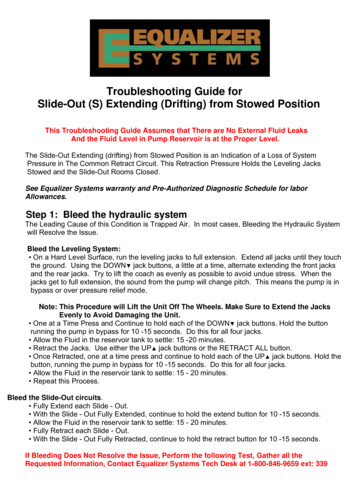
Troubleshooting Guide forSlide-Out (S) Extending (Drifting) from Stowed PositionThis Troubleshooting Guide Assumes that There are No External Fluid LeaksAnd the Fluid Level in Pump Reservoir is at the Proper Level.The Slide-Out Extending (drifting) from Stowed Position is an Indication of a Loss of SystemPressure in The Common Retract Circuit. This Retraction Pressure Holds the Leveling JacksStowed and the Slide-Out Rooms Closed.See Equalizer Systems warranty and Pre-Authorized Diagnostic Schedule for laborAllowances.Step 1: Bleed the hydraulic systemThe Leading Cause of this Condition is Trapped Air. In most cases, Bleeding the Hydraulic Systemwill Resolve the Issue.Bleed the Leveling System: On a Hard Level Surface, run the leveling jacks to full extension. Extend all jacks until they touchthe ground. Using the DOWN jack buttons, a little at a time, alternate extending the front jacksand the rear jacks. Try to lift the coach as evenly as possible to avoid undue stress. When thejacks get to full extension, the sound from the pump will change pitch. This means the pump is inbypass or over pressure relief mode.Note: This Procedure will Lift the Unit Off The Wheels. Make Sure to Extend the JacksEvenly to Avoid Damaging the Unit. One at a Time Press and Continue to hold each of the DOWN jack buttons. Hold the buttonrunning the pump in bypass for 10 -15 seconds. Do this for all four jacks. Allow the Fluid in the reservoir tank to settle: 15 -20 minutes. Retract the Jacks. Use either the UP jack buttons or the RETRACT ALL button. Once Retracted, one at a time press and continue to hold each of the UP jack buttons. Hold thebutton, running the pump in bypass for 10 -15 seconds. Do this for all four jacks. Allow the Fluid in the reservoir tank to settle: 15 - 20 minutes. Repeat this Process.Bleed the Slide-Out circuits. Fully Extend each Slide - Out. With the Slide - Out Fully Extended, continue to hold the extend button for 10 -15 seconds. Allow the Fluid in the reservoir tank to settle: 15 - 20 minutes. Fully Retract each Slide - Out. With the Slide - Out Fully Retracted, continue to hold the retract button for 10 -15 seconds.If Bleeding Does Not Resolve the Issue, Perform the following Test, Gather all theRequested Information, Contact Equalizer Systems Tech Desk at 1-800-846-9659 ext: 339
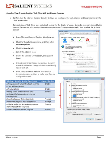
Step 2: Perform Hose Routing TestThis section outlines the test procedure for assuring proper hydraulic hose connections. Properhose connections are critical to system operation to ensure full retract path pressure. Identify thetype of pump assembly either Unidirectional or Bi-rotational, and perform the appropriate test.UnidirectionalNote: This guide only applies to coaches equipped with a unidirectional pump assembly.1) Run all slide-outs to a one-half extended position.2) Manually open valve labeled as DV1 on the power unit manifold. This valve will be equippedwith red manual override knob. To shift the valve: pull out on the knurled knob and then rotate theknob ¼ turn to hold in the open position. This operation must be done by hand: No Tools!3) Individually operate each slide-out via its wall switch. If the valve has been properly shifted,each slide-out will only run in one direction. It will not matter what direction the wall switch ispressed. Take note of the only direction each slide-out will move: either Extend or Retract.4) After testing, return DV1 to the normal operational position. Rotate the red knurled knob onDV1 until it “snaps” back into the “IN” position.5) Record Your Results and Report to the Equalizer Systems Tech Desk.Note: Depending on the Model of Unit being Tested, Slide - Outs, even Properly Plumbed, mayOperate in Different Directions. This makes it very important to Consult with the Equalizer SystemsTech Desk before making any Plumbing Changes.DV1Identified By: “DV1” stamped into manifold Coil wires: (1) Green, (1) Black Red Knurled KnobOne (1) Motor Solenoid
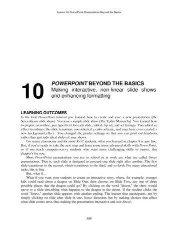
Bi-Rotational Pumps are Identified by Two (2) Motor Solenoids Attached to the Pump Motor.Three (3) Vertical Buttons on the Left Side of the Control Panel Identify “Old” Platform Controllers.This Style Integrates Controller and Keypad into One Unit.Bi-rotationalNote: This Guide Only Applies to Coaches Equipped with Bi-Rotational Pump Assembly.1) With all leveling jacks retracted, run all hydraulically operated slide-outs to the one-halfextended position.2) Manually open cartridge valves for slide rooms on the pump manifold. These will be the valveslocated in the V-5, V-6, V-7, V-8, etc. positions (V-1 through V-4 are for the leveling jacks). Thevalves are opened by turning the Stem Screw ( Flat Blade Screwdriver or Allen Screw) all the wayClockwise until Lightly Seated (approximately 2 - 3 turns).3) Press the UP arrow key on the leveling system keypad corresponding with the Left FrontLeveling Jack to Manually Retract the Left Front Jack (even though it is already retracted).Do Not Press the ALL RETRACT Button.4) Note which Direction each Individual Slide Operates (EXTEND or RETRACT).Smaller / Lighter Slides May Operate before the Heavier Ones. Once the Lighter Slide(s) reach theLimit of their travel, the Larger Slides will Begin to Move.5) Record Your Results and Report to the Equalizer Systems Help Desk.6) When Finished Testing, Make Sure to Return Valves to Operating Position.Note: Depending on the Model of Unit, Slide - Outs, Even Properly Plumbed, May Operate inDifferent Directions When Tested. This Makes it Very Important to Consult with the EqualizerSystems Tech Desk Before Making Any Plumbing Changes.
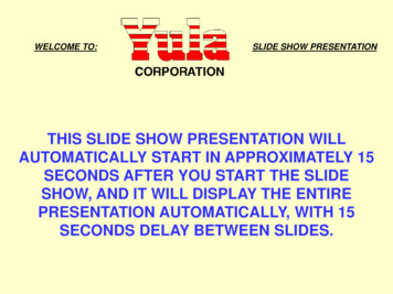
Step 3: Check for Paint on Hydraulic Cylinder RodsPaint Overspray / Undercoating on the Chrome Cylinder Rod can flake off inside the cylinder andCause damage to the internal seals. This seal damage could lead to an internal bypass.Check for Body Paint / Undercoating or Overspray on Room Slide Cylinder Rod and the Slide OutInner Track. Check the Entire Length of the Extended Rod. Paint may cause the Chrome SurfaceFinish to Feel Rough / Look Pitted. The Cylinder may Show signs of Overspray Residue collectingOn the Outer Tube at the Rod Gland. Black Paint / Undercoating near or on the Threaded PortionAt the End of the Cylinder Rod is Normal. This Black Paint is Applied to the Cylinder during It’sManufacturing Process.Paint On: Slide - Out TrackPaint On: Cylinder (Ram) Shaft
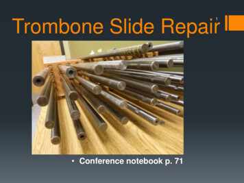
Step 3: Gather System InformationPlease Gather the Following Information and Call Equalizer Systems.Coach Info: Year : Model : Floor Plan : Unit Serial Number- Note: this is usually not the VIN #:Leveling System: Pump Assembly Model #: Starts with a S10?T*? . Leveling Controller part # and version #, example ( 2730 V1.16 ) Pressure Switch Type: Old or New ?Pressure Switch IdentificationOld Platform StyleNew Platform StyleNew Style Pressure Switch, Equalizer Systems Part # 2047 Approx. 1.75 inches in diameter, Black plastic outer case construction Two Threaded Studs for wire attachment. Backwards compatible with old switch.Old Style Pressure Switch, Obsolete Approx. 1.25 inches in diameter Half gold metal, half black plastic outer case construction Two Spade Connectors for wire attachment.
How to Find Auto-Level Controller Part NumberFive ( 5 ) Vertical LED Lights on the Left Side of the Keypad Identify “New” Platform Controllers.The Controller is a Remotely Mounted Box. Usually Located Between the Main Frame Rails andBetween the Front and Rear Axles. The Controller (Black Box) is approx. 10” x 5” x 1.5”. The Part Number andVersion Code are Included on the Label.ControllerBlack Box
5) Record Your Results and Report to the Equalizer Systems Help Desk. 6) When Finished Testing, Make Sure to Return Valves to Operating Position. Note: Depending on the Model of Unit, Slide - Outs, Even Properly Plumbed, May Operate in Different Directions When Tested. This Makes it Very Important to Consult with the Equalizer