Transcription
Comparison of Quantity-Distance Standards for Earth-Covered Magazines inVarious National/International ManualsDavid D. Bogosian1 & Jon Chrostowski21Baker Engineering and Risk Consultants, Inc.360 N. Pacific Coast Hwy., Suite 1090El Segundo, CA 90245, USAdbogosian@bakerrisk.com2ACTA, Inc.2790 Skypark Drive, Suite 310Torrance, CA 90505, USAchrostowski@actainc.comKeywords: earth-covered magazine, igloo, separation distance, IMD, standardsABSTRACTNational and multi-national agencies tasked with regulation of explosives storage have produced a number of differentmanuals governing the maximum amounts of HD 1.1 material that can be stored in an earth-covered magazine (ECM).These quantity-distance (Q-D) requirements are set forth in prescriptive language in manuals published for use by theengineering and planning community.A recent comprehensive review of five such manual sources resulted in a compilation of a set of comparative tablesin which the requirements for minimum separation distance, as well as for blast loading on various elements of theECM, were outlined side by side. The five manuals represent requirements for the United Kingdom, Canada, andU.S.A., as well as multi-national entities such as NATO and the United Nations. All manuals use the same designationsfor categories of ECMs (namely, 7-bar, 3-bar, or undefined). But the actual requirements, both in terms of scaleddistances and the applied loading (pressure and impulse), are not entirely consistent across the various requirements.This paper identifies some of those inconsistencies, as well as potential inconsistencies in the correlation betweenseparation distance and its corresponding pressure and impulse.BACKGROUNDIn early 2017, BakerRisk was engaged by the Department of National Defence, Canada, to evaluate their long-spanearth covered magazine (ECM) design for blast loads from an accidental detonation in an adjacent magazine. Thestudy was a comprehensive one involving high-fidelity finite element models of structural response as well as thelatest analytical estimates of blast loads from ECMs. That study is documented in a separate paper [1], as well as afully detailed technical report [2].In the course of that study, the authors were tasked to review a broad range of national and international safetystandards for storage of ammunition, particularly as they related to design requirements for siting of ECMs. Five suchstandards were identified representing the US, UK, UN, NATO, and Canadian requirements. All are formulated interms of quantity-distance (Q-D), and so they all provide minimum separation distances; in addition, most provide atleast some design loads (pressure and impulse) that ECMs must satisfy in order to qualify for one of three differentstandard ratings, depending on the load that the headwall of the ECM is designed to resist: 7-bar 3-bar Undefined
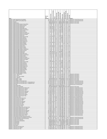
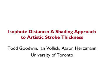
International Explosives Safety SymposiumAugust 2018It may come as no surprise that, when aligned against one another, the five references do not align perfectly, and infact present certain glaring points of dissimilarity. This paper attempts to compare those standards and highlight theirareas of agreement as well as disagreement. We are not so bold as to offer a suggested path towards harmonization ofthe standards, but it is our hope that this paper may stimulate discussions among the various parties involved that may,one day, result in such a harmonization.DEFINITIONSFor clarity, the assumed configuration of ECMs in a constructed array is shown in Figure 1. The requirements forseparation distance from the donor (or potential explosion site, PES) to the acceptor (or exposed site, ES) areprescribed in terms of clear distances from the nearest surfaces of each ECM. These are termed the inter-magazinedistance, or IMD. Note that these would not be the same distances one might use to calculate blast load as a functionof charge weight and distance. In the latter case, an alternate set of dimensions would be used from the centroid of theexplosive mass (generally the centroid of the magazine, unless one knows that the storage arrangement would bedeliberately skewed or off-center) to the center of the structural component being evaluated. This is illustrated inFigure 2. For example, the side-to-side load on the roof of an acceptor would be calculated from the centroid of thedonor to the centroid of the acceptor, and could be a significantly larger distance than that used for the side-to-sideseparation distance, depending on the plan dimensions of the re 1: Definition of separation distances between ECMs.Acceptor(ES)D for frontload on roofD for side load onheadwallDonor(PES)D for rear loadon headwallAcceptor(ES)D for side load on roofAcceptor(ES)Figure 2: Examples of definition of distances for blast load computations.We mention this here because this too is a potential source of confusion for novice users of the published standards,and to our knowledge, none of the standards go to any length in clarifying this distinction. Use of similar verbal terms(side-to-side distance, for example) referring to two different quantities carries the potential for misunderstanding andmisapplication, and may be avoided with the use of clarifying graphics such as those above.[2]
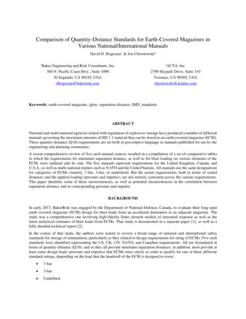
International Explosives Safety SymposiumAugust 2018SOURCESThe five jurisdictions consulted were the United States, United Kingdom, United Nations, North Atlantic TreatyOrganization, and Canada. Each publishes a voluminous body of technical literature, from which the relevantdocuments were identified. The specific documents and the sources for the data to be presented in the tables in theremainder of this paper are cited below. United States: DoD 6055.09-M [3] establishes safe stand-off distances between various PESs and ESs. ForIMD, the pertinent tables are Table V3.E3.T6 (HD 1.1 IMD Hazard Factors) and Tables V3.E3.T7 (QD forHD 1.1 AE for K 1.1, 1.25, 2, 2.75, 4.5 and 5) and V3.E3.T8 (QD for HD 1.1 AE for K 6, 8, 9, 11, 18and 40). ECM component design blast loads are defined in Vol. 2, Para. V2.E5.5.2.4. United Kingdom: JSP 482 [4] establishes safe stand-off distances between various PESs and ESs. For IMD,the pertinent tables used are in Chapter 10, Section 2, Annex A, Table 1A (HD 1.1 QD Matrix for EarthCovered Storage). ECM component design blast loads are defined in Chapter 6, Annex A, Para. 1.2 (DesignLoads for Igloos as Exposed Site). United Nations: IATG 02.20 [5] establishes safe stand-off distances between various PESs and ESs. ForIMD, the pertinent tables used are in Annex A, Table D.2 (Hazard Division 1.1 QD Matrix (above groundstorage, NEQ 50 kg). ECM component design blast loads are defined in a separate document, IATG 05.20[6], Annex C, Para. C.1.1 (Design Loads for Igloos as Exposed Site). NATO: AASTP-1 [7] provides IMDs for ECMs in Section II, Table 1A (HD 1.1 QD Matrix for EarthCovered Storage). ECM component design blast loads are defined in Section II, Para. 2.3.2.2-2 (Design Loadfor Head-Walls and Doors). Canada: DND Canada has issued C-09-005-0021 [8] as that country’s explosive safety standard. QD tablesare provided in Appendix A, Section II, Table A-2 starting on p. A-13. These are identical in form and contentto those in the NATO standard AASTP-1 (at least with regard to the ECM PES and ES combinations).However, to the best of our ability to determine, tables or paragraphs providing design loads for ECMs arenot provided.SEPARATION DISTANCESWe first consider the IMD separation distances between adjacent ECMs, which once again are defined in terms of thedistances shown in Figure 1. The required distances are listed in Table 1 for all three loading directions, all three PEStypes, and all five jurisdictions. Where divergences regarding level of protection were present in the manuals, thoseare noted in the footnotes. The values are provided in metric scaled distances, where the distance is normalized by thecube root of the net explosive quantity (NEQ). Cells containing values that seem at odds with the consensus arehighlighted with color.Consideration of the table indicates many areas of consistency across all five jurisdictions, as well as a number ofareas of inconsistency. Roundoff aside, all five documents agree identically on all three distances for 7-bar magazines.There is near unanimity for 3-bar magazines with only two exceptions. One is the UK which allows 0.8 instead of 1.8m/kg1/3 separation from rear to front and is thus less conservative than the others. 1 This is doubly curious because it isthe only instance of disagreement between the UK and UN/NATO/Canada. Furthermore, keeping the rear-to-frontdistance (which controls headwall loads) the same between 3-bar and 7-bar magazines seems inappropriate, given thevery definition of the 3-bar and 7-bar values. The other exception, the absence of a side-to-side value from Canada,appears to be a formatting issue in the published version of the table, where the schematic figure and the D-value havebeen cut off at the top of the table (Figure 3).1Note that JSP 482 provides separation distances for a receptor (ES) magazine that is “a standard UK igloo designed inaccordance with Chapter 6” without distinguishing between 3-bar and 7-bar designs, both of which are covered in Chapter 6.We have interpreted this to mean that the separation distances should be applied equally for both designation. Other manuals(NATO, UN, Canada) clearly distinguish the 3-bar from the 7-bar ES in their tables.[3]
International Explosives Safety SymposiumAugust 2018Table 1: Minimum scaled separation distances [m/kg1/3] for ECMs.Receptor(PES) 80.80.80.8Front-to-rear0.790.80.80.80.8(a) for NEQ 113,400 kg(b) for NEQ 113,400 kg(c) for virtually complete protection(d) for high degree of protection (no primary explosives, no items vulnerable to spall)(e) assuming the ES has a headwall and hardened door; high degree of protection?Top of rowcut offProperrowFigure 3: Missing information for 3-bar magazine, side-to-side loading (extract from [8]).For the Undefined magazine, there are two values that stand in contrast with the majority consensus, and both belongto the US. For both side-to-side as well as front-to-rear loads, the US allows significantly smaller separation distances.The comparison is less clear because of the ambiguities in application (US distinguishes large from small NEQs, whilethe others distinguish between varying levels of protection). Nevertheless, the US is significantly less conservativethan the other jurisdictions in the side-to-side and front-to-rear spacing, but it is quite consistent in the rear-to-frontspacing.[4]
International Explosives Safety SymposiumAugust 2018DESIGN LOADINGWe turn next to the loads for which an ECM is to be designed (Table 2), and here the situation grows more complex.First, there are two load values to consider, pressure and impulse. Second, the standards are far less thorough inprescribing loads than they were in prescribing IMDs; in this case, much of the table is blank. Third, since there arefewer “votes,” it is harder to determine a consensus opinion and identify outliers.Table 2: Prescribed design pressures and scaled impulses for ECMs.MetricDonor(PES)ECM ��———Side wall—————Head wall300300300——Roof745600600——Side wall—300300——Head wall700700700700*—Roof745600600——Side wall—300300——Head wall—————170————Side wall—————Head wall100100100——Roof170100100——Side wall—100100——Head �—Head se[kPams/kg1/3]3-bar7-barRoofRoofSide wallNATOCanada(*) for NEQ 75,000 kgLet’s begin with the obvious: Canada does not prescribe any design loads at all. Coming close behind, NATO onlygives head wall loads for 7-bar magazines and nothing else. Those loads apply for NEQ of 75,000 kg or less; for largerNEQs, designers are advised to consider using higher values (but no actual value is prescribed).The remainder of our discussion will pertain to the US, UK, and UN documents. First, for Undefined magazines, theonly requirement comes from the US and applies to the roof load only. Second, for 3-bar magazines, the USrequirement for the roof is higher than that of its peers: 745 instead of 600 kPa for the pressure, and 170 instead of100 kPa-ms/kg1/3 for the impulse. Thus, for the roof of the 3-bar, the US is more conservative than other nations, butfor the head wall it is in agreement; for the side wall, it is silent. Third, looking at the 7-bar values, the UK and UNagree closely with one another, but the US is of another opinion altogether in virtually every load metric. It is moreconservative for the roof load (both pressure and impulse), but on the head wall impulse it is less conservative. TheUS abstains on side wall loads altogether.In the current climate of international military cooperation between these countries and/or agencies, it is often desirableto construct a magazine that satisfies all relevant jurisdictions. Table 3 presents the worst-case design loads for 3-bar[5]
International Explosives Safety SymposiumAugust 2018and 7-bar magazines from all the standards considered (Undefined not having enough requirements to merit inclusionin the table). Were one to design to the loads in Table 3, one could confidently assert that the magazine in questionsatisfies all five standards. As the table indicates: The US is most conservative in the roof loads; The UK and UN are most conservative in the side wall loads; And with the exception of the US, all agree on the head wall loads.Table 3: Worst-case design pressures and mponentQD Standards for 7-bar ECMQD Standards for 3-bar ECMValueSourceValueSourceHead wall700US / UK / UN /NATO*300US / UK / UNRoof745US745USSide wall300UK / UN300UK / UNHead wall200UK / UN / NATO*100US / UK / UNRoof170US170USSide wall100UK / UN100UK / UN(*) Limited to NEQ 75,000 kgSOME QUALITATIVE QUESTIONS OF CONSISTENCYWe may pause to reflect on the IMD and blast load requirements, and make some inquiries regarding their consistency.Obviously, distance should correlate to pressure and scaled impulse, and so it is appropriate to expect that if onechanges, so should the others. Consider the design loads for the roof prescribed by the US. For all magazine types, p 745 kPa and i 170kPa-ms/kg1/3. And yet the prescribed side-to-side distance (which presumably controls the roof) varies from0.79 to 0.50 m/kg1/3. Might we not expect the roof load to increase when the scaled distance is reduced? The rear-to-front standoff for 3-bar magazines, as prescribed by the UK, seems erroneous as discussedpreviously. If head wall loads are reduced from 7 bar to 3 bar for the two different categories, how can therear-to-front separation distance remain constant at 0.8 m/kg 1/3 between those categories?Speaking more generally, one may wonder at the necessity of prescribing both a separation distance (in scaled terms)as well as a design load. Would not one or the other suffice? Given a scaled distance and a loading model (such as theKingery-Bulmash model for TNT), distance directly correlates to pressure and scaled impulse. Clearly that would notaccount for some of the complexities of interaction between the detonation and the donor magazine structure, or theimpact of debris on the acceptor magazine, but if the designer was given a separation distance and a loading model,the loads could be calculated directly without having to be specified separately. Specifying both distance and loadingseems like a duplication and leads to ambiguity. Is it sufficient merely to satisfy the IMDs, or must the structure bedesigned for the specified loads even when it satisfies IMD? What if the site layout exceeds the IMD requirements(larger spacings), do the design loads remain unchanged? Surely they should be reduced in that case.A QUANTITATIVE CHECK ON CONSISTENCYA blast model does in fact exist that, unlike Kingery-Bulmash, is directly applicable to ECMs and can be used tocalculate a distinct pressure and impulse in each of three directions from a donor ECM: front, side, and rear. Thismodel [9] and its associated spreadsheet tool (the Blast Effects Computer, or BEC) have been sponsored by the USDDESB, but they are not (yet) approved for use in design. A closely related model was also sponsored by NATO [10];[6]
International Explosives Safety SymposiumAugust 2018while there is no official prohibition against its use in design, there is also no official endorsement for that purpose.Both represent curve fits to a large set of experimental data and are accepted within the community as state-of-the-artwith regard to blast loads from an ECM. Both models yield results that are essentially identical from a numerical pointof view, even though they are formulated quite differently in mathematical terms. The main application of this model(considering both BEC and AASTP-4 as a single model) is in risk analysis methods. However, using it as a check ondesign would be natural to anyone who knew of its existence.For demonstration purposes, we have devised a “sample problem” in which a rectangular array of ECMs, each onemeasuring 8 12 meters, has been sited with the prescribed minimum scaled standoff distances for 7-bar magazines(per Table 1). Note that for the 7-bar ECM, all five manuals are in unanimous agreement on the distance requirements,which streamlines our problem. We assume each ECM will store a quantity of 27,000 kg of TNT, from which theactual distances can be easily calculated. This layout is illustrated in Figure 4.23 m(b) Side-to-sideroof load24 m 0.8 m/kg1/3(TYP.)12 m8m(a) Rear-to-fronthead wallloadW 27,000 kg15 m 0.5 m/kg1/330 mFigure 4: Dimensions and layout of ECMs for sample calculation.Let us, for demonstration purposes, calculate two loadings: (a) the rear-to-front loads on the headwall, and (b) theside-to-side loads on the roof. Both of these are illustrated in These results should be of concern to those who manageand administer these standards documents. True, BEC is not currently authorized for use in design, but any designerworking in the explosives safety domain will know about it and will be curious to apply it to a problem such as this.Seeing such divergent results as those illustrated herein will surely raise eyebrows and call into question theapplicability of either the loading model and the prescribed standoffs, or the prescribed loads, or both. Perhaps if BECwas consistently non-conservative relative to the standards, the situation could be explicable as a case of the standardsbeing overly conservative, with the experienced user free to adopt methods of greater analytical fidelity. But there isno clear trend of conservatism in these results.Table 4. For case (a), the actual distance from the center of the charge to the headwall component is 30 m (includinghalf the length of the ECM), while for case (b) it is 23 m (including one full width of the ECM) from the center of thedonor to the center of the roof of the acceptor. Using these distances and the appropriate loading model in BEC (ECMrear for (a) and ECM side for (b)), we calculate values of pressure and impulse that are listed in These results shouldbe of concern to those who manage and administer these standards documents. True, BEC is not currently authorizedfor use in design, but any designer working in the explosives safety domain will know about it and will be curious toapply it to a problem such as this. Seeing such diver
Comparison of Quantity-Distance Standards for Earth-Covered Magazines in Various National/International Manuals David D. Bogosian1 & Jon Chrostowski2 1Baker Engineering and Risk Consultants, Inc. 2ACTA, Inc. 360 N. Pacific Coast Hwy., Suite