Transcription
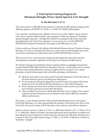
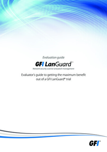
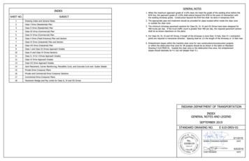
GENERAL NOTESINDEX1.When the maximum approach grade of 10% does not meet the grade of the existing drive before theR/W line, the approach grade of 10% shall extend beyond the R/W to the point of intersection withSHEET NO.SUBJECT1Drawing Index and General Notes2Class I Drive (Residential) Plan3Class II Drive (Residential) Plan4Class III Drive (Commercial) Plan5Class IV Drive (Commercial) Plan6Class V Drive (Field Entrance) Plan and Section7Class VI Drive (Industrial) Plan and Section8Class VII Drive (Industrial) Plan9Class I and Class III Drives Approach Gradesthe existing driveway grade. Construction beyond the R/W line shall be done in temporary R/W.2.The appropriate pipe end treatment should be provided for pipes located either inside the clear zoneor outside the clear zone.3.The minimum driveway pavement sections for Class III, IV, VI and VII Drives have been designed for400 trucks per day. If the truck traffic count is greater than 400 per day, the required pavement sectionshall be as shown elsewhere on the plans.4.For Class III, IV, VI and VII Drives, if length of the driveway is more than 15 feet, then D-1 contractionjointsare required in transverse direction. Spacing shall be 1/2 the length of the driveway or 15 feet max.5.Embankment slopes within the mainline clear zone for new construction/reconstruction projectsor within the obstruction-free zone for 3R projects should be as shown in the table on StandardDrawing E 610-PRAP-01. Outside the clear zone or the obstruction-free zone, the embankmentslopes should desirably be 4:1 but not steeper than 3:1.10Class II and Class IV Drives Sections11Class II, IV & V Drives Approach Grades12Class VI Drive Approach Grades13Class VII Drive Approach Grades14Joint Placement, Corner Reinforcing, Monolithic Curb, and Concrete Curb and Gutter Details15Private Drive Crossover Plans16Private and Commercial Drive Crossover Sections17Commerical Drive Crossover Plans18Pavement Wedge and Pay Limits for Class II, IV and VII DrivesINDIANA DEPARTMENT OF TRANSPORTATIONINDEXGENERAL NOTES AND LEGENDSEPTEMBER 2019STANDARD DRAWING NO.E 610-DRIV-015/1/2019DESIGN STANDARDS ENGINEERDATE6/5/2019CHIEF ENGINEERDATE
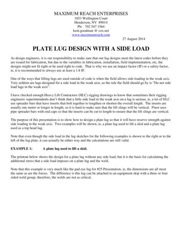
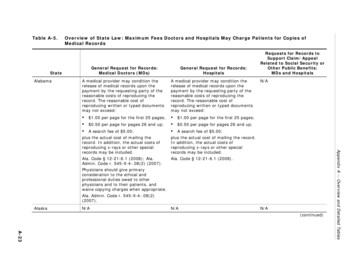
Tem porary R/W ifreq'd.5'-0" minimum10'-0" desirableExistingGrade Intersect Pointean elleanav glrtniokr.tpadjaot.n.ijmad".0ni'm20" 0R'10R Drive10'-0" (min.)20'-0" (max.)S1. See Standard Drawing series E 610-DRIV-14 for joint placement,corner reinforcing, monolithic curb, and concrete curb and gutterdetails.2R 10'0"or R/WNOTES:See Standard Drawing E 604-SDWK-03 sidewalk driveway crossingdetails.or R/W3. See Standard Drawing E 610-DRIV-09 for Sections A-A and B-B.SidewalkM22SidewalkGutter LineBuffer1/2" Preformed Joint Filler (Typ.)Edge of HMA PavementMonolithic CurbConcrete Curb and Gutter (typ.)1/2" Preformed Joint FillerMonolithic CurbStreetPLAN VIEWCONCRETE CURB AND GUTTERLEGENDMPCCP for Approaches, 6 in., onDense Graded Subbase, 6 in., onSubgrade Treatment Type II (6 in. Coarse Aggregate No. 53)S5'-0" minimum10'-0" desirableExistingDriveSidewalk Elevation TransitionTem porary R/W ifreq'd.10'-0" (min.)20'-0" (max.)SA,Bor R/WFor type and thickness equivalent to surface in place, see plans.Grade Intersect Pointeanll neeaav glrtnioktr.jpaad to.nidjm".a0ni'm200"R 0'1R INDIANA DEPARTMENT OF TRANSPORTATIONCLASS I DRIVER 10'0"(RESIDENTIAL)or R/WSEPTEMBER 2019SidewalkM22SidewalkSTANDARD DRAWING NO.E 610-DRIV-02BufferIntergal Curb5/1/20191/2" Preformed Joint Filler (Typ.)A,BMonolithic CurbMonolithic CurbDESIGN STANDARDS ENGINEERDATE1/2" Preformed Joint FillerStreet6/5/2019PLAN VIEWCHIEF ENGINEERINTEGRAL CONCRETE CURBDATE
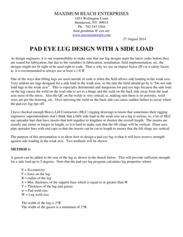
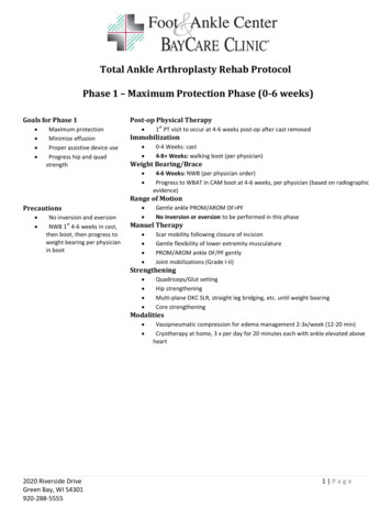
4'-0" Desirable4'-0" Desirable12'-0" (min.)12'-0" (min.)5'-0" minimum24'-0" (max.)R25'-0"of ditchShoulder break Shoulder break30'-0"RRTem p.R/WTem p.R/Wifreq'd.Length variable "-0'1515'0"Pipe End Treatment (Typ.)M "-0'52R/WRVariableof ditchRSR/WPipe End Treatment (Typ.)MSSR/WR/WConnect to drive in placeFVariableSLength variableTem porary R/WVariableSS24'-0" (max.)10'-0" desirable D, ETem p.R/W10'-0" (desirable)ifreq'd.Tem porary R/W5'-0" (min.)Tem p.R/WConnect to drive in placeEdge of paved shoulder8'-0" or greater in widthFPaved shoulder lessTNTthan 8'-0" width.Edge of travel laneNTTEdge of travel laneD, EPLAN VIEWPLAN VIEW(PAVED SHOULDER LESS THAN 8'-0" IN WIDTH OR UNPAVED SHOULDER)(PAVED SHOULDER 8'-0" OR GREATER IN WIDTH)LEGENDNOTES:M HMA for Approaches, Type BINDIANA DEPARTMENT OF TRANSPORTATION165#/syd HMA Surface Type B on1. See Standard Drawing E 610-DRIV-10 for Section S-S.2See Standard Drawing E 610-DRIV-11 for Sections D-D, E-E and F-Ffor approach grades.275#/syd HMA Intermediate Type B onCLASS II DRIVE6" Compacted Aggregate No. 53, on(RESIDENTIAL)Subgrade Treatment Type II (6 in. Coarse Aggregate No. 53)orPCCP for Approaches, 6 in., on3. The radii for PCCP Class II drives shall be constructed using cornerreinforcement as detailed in Standard Drawing E 610-DRIV-14.4. For PCCP Drives see Standard Drawing E 610-DRIV-14 for jointplacement details.Dense Graded Subbase, 6 in., onSubgrade Treatment Type II (6 in. Coarse Aggregate No. 53)SEPTEMBER 2019STANDARD DRAWING NO.E 610-DRIV-03N The greater thickness of either the drive M5/1/2019or the paved shoulder T section.S For type and thickness equivalentDESIGN STANDARDS ENGINEERDATEto surface in place, see plans.6/5/2019T Plan shoulder section.CHIEF ENGINEERDATE
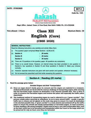
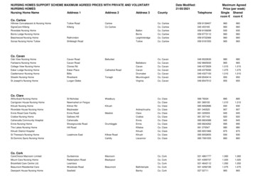
5'-0" minimum10'-0" DesirableGrade intersect pointExisting Drive20'-0" (min.)NOTES:Tem porary R/W ifreq'd.40'-0" (max.)1.or R/WSee Standard Drawing E 610-DRIV-09 for Section A-A, and Section B-B.or R/WS2R See Standard Drawing E 604-SDWK-03 for sidewalk driveway crossing details.R 20'-0" min. adj. to traffic lane10'0"3.R 10'-0" min. adj. to parking laneSee Standard Drawing E 610-DRIV-14 for joint placement, monolithic curb,and concrete curb and gutter details.Monolithic curbSidewalkMonolithic curb2M2Gutter lineSidewalkBufferConcrete curb and gutter1/2" Preformed Joint FillerConcrete curb and gutterPLAN VIEWEdge of HMA pavementCONCRETE CURB AND GUTTERLEGENDM PCCP for Approaches, 9 in., onDense Graded Subbase, 6 in., onGeogrid Type 1B, on5'-0" minimumSubgrade Treatment Type II (6 in. Coarse Aggregate No. 53)Grade intersect point10'-0" DesirableExisting DriveS For type and thickness equivalent to surface in place, see plans.20'-0" (min.)Sidewalk elevation transitions.40'-0" (max.)Tem porary R/W ifreq'd.A, BSor R/Wor R/WINDIANA DEPARTMENT OF TRANSPORTATIONR 20'-0" min. adj. to traffic laneR R 10'-0" min. adj. to parking lane10'0"CLASS III DRIVE(COMMERCIAL)Monolithic CurbMMonolithic CurbSEPTEMBER 20192SidewalkSidewalkSTANDARD DRAWING NO.2E 610-DRIV-04Buffer5/1/2019Integral curb (Typ.)1/2" preformed joint filler1/2" Preformed Joint FillerDESIGN STANDARDS ENGINEERA, BDATEStreet6/5/2019PLAN VIEWINTEGRAL CONCRETE CURBCHIEF ENGINEERDATE
4'-0" DesirableNOTES:20'-0" (min.)40'-0" (max.)Connect to drive in placeFLength variableP2. See Standard Drawing E 610-DRIV-10 for Section P-P.Tem p.R/W5'-0" minimum10'-0" desirable3. For PCCP Drives, see Standard Drawing E 610-DRIV-14 for jointplacement details.PSR/WLEGENDPipe End Treatment (Typ.)of DitchVariable MHMA for Approaches, Type B,165 lbs/syd HMA Surface, Type B, on75'-0" (min.)275 lbs/syd HMA Intermediate, Type B, on "-0'02660 lbs/syd HMA Base, Type B, onR50'-0" (min.)20'-0"MREdge of paved shoulderTem p.R/Wifreq'd.Tem porary R/W1. See Standard Drawing E 610-DRIV-11 for Sections D-D, E-E and F-F.Shoulder breakEdge of paved shoulderSubgrade Treatment Type II (6 in. Coarse Aggregate No. 53), onGeogrid, Type 1BorPainted lineNTPCCP for Approaches, 9 in., onTPainted lineDense Graded Subbase, 6 in., onEdge of travel laneGeogrid Type 1B onSubgrade Treatment Type II (6 in. Coarse Aggregate No. 53)FShoulder exclusion (HMA shoulder only)NThe greater thickness of either the drive Mor the paved shoulder Tsection.PLAN VIEW(PAVED SHOULDER 8'-0" FEET OR GREATER IN WIDTH)SFor type and thickness equivalentto surface in place, see plans.4'-0" DesirableT20'-0" (min.)5'-0" minimum10'-0" desirablePlan shoulder section.40'-0" (max.)Tem p.R/WLength variableR shoulderPavedVariableTD, EPR/WTem p.R/Win placeifreq'd.Tem porary R/WConnect to driveINDIANA DEPARTMENT OF TRANSPORTATIONCLASS IV DRIVE(COMMERCIAL)PSPipe End Treatment (Typ.)20'0""-0'02MSEPTEMBER 2019STANDARD DRAWING NO. E 610-DRIV-05of DitchRShoulder breakN5/29/2019TDESIGN STANDARDS ENGINEERD, EEdge of travel lanePLAN VIEW(PAVED SHOULDER LESS THAN 8'-0" IN WIDTH OR UNPAVED SHOULDER)DATE6/5/2019CHIEF ENGINEERDATE
NOTES:32'-0" (desirable min.)4' desirable24'-0" (min.)Connect to drive40'-0" (max.)in place1. See Standard Drawing E 610-DRIV-11 for sections D-D, E-E, and F-F.25'-0" minimum10'-0" desirableR/Wlane. Where the paved shoulder width is 8'-0" or more, the drive radiishall be tangent to the edge of the paved shoulder.R/WALength variableWhere the shoulder is earth or aggregate or the paved width is lessthan 8'-0", the drive radii shall be tangent to the edge of the travelTem p.R/WD,E & FTem p.R/Wifreq'd.Tem porary R/W4' desirableAPipe End Treatment (Typ.)of ditchR 25'-0""-0'52 RUnimprovedsurfaceShoulder breakShoulder breakEdge of travel lane or 2paved shoulderD, E & FPLAN VIEWINDIANA DEPARTMENT OF TRANSPORTATIONCLASS V DRIVE32'-0" (desirable min.)4' Desirable(FIELD ENTRANCE)4' Desirable24'-0" min.SEPTEMBER 201940'-0" max.1:e4polSUnimproved surface1:e6polS2%2%STANDARD DRAWING NO.E 610-DRIV-06Slope6:15/1/2019DESIGN STANDARDS ENGINEERDATESECTION A-A6/5/2019CHIEF ENGINEERDATE
32'-0" Min.50'-0" Max.Temporary R/W for drive construction if requiredGrade Interesect Point10'0"(See plan & profile sheet for limits)10'-0"R/W10'-0"SPipe End Treatment (Typ.)R/WDMD20'0"Shoulder Break40'0"25'-0"4'-0" (Min.)FENMax.11'0"NPaved ShoulderrShoulder BreakPainted Line2%Painted LineNPaved ShoulderEdge Travel LaneE75'-0" Taper65'-0"F65'-0"75'-0" TaperPLAN VIEWNOTES:11'-0" max.1. See Standard Drawing E 610-DRIV-12 for drive approach grades.NSlope6:12. Class VI Drive accommodates a WB-67 (IDV) design vehicle with a45'-0" turning radius.SECTION E-E3. For PCCP Drives see Standard Drawing E 610-DRIV-14 for jointplacement For 400 Trucks per dayHMA for Approaches, Type B,165 lbs/syd HMA Surface, Type B, on275 lbs/syd HMA Intermediate, Type B onSECTION D-DINDIANA DEPARTMENT OF TRANSPORTATIONCLASS VI DRIVE(INDUSTRIAL)660 lb/syd HMA Base, Type B onSubgrade Treatment Type II (6 in. Coarse Aggregate No.53), onSEPTEMBER 2019Geogrid, Type 1B11'-0" maxorSTANDARD DRAWING NO.E 610-DRIV-07PCCP for Approaches, 9 in., on10'-0" max.Dense Graded Subbase, 6 in., onShoulder section asspecified in plansGeogrid, Type 1B, onShoulder Break5/1/2019Subgrade Treatment Type II (6 in. Coarse Aggregate No.53)Slope6:1N The greater thickness of either the drive MDESIGN STANDARDS ENGINEERDATEor the paved shoulder section.SECTION F-F6/5/2019S For type and thickness equivalentto surface in place, see plans.CHIEF ENGINEERDATE
NOTES:DriveDrive1. See Standard Drawing E 610-DRIV-12 for Sections A-A, B-B and C-C.32'-0" Min.Temporary R/W for drive50'-0" Max.2Grade Intersection Pointconstruction if requiredSee Standard Drawing E 604-SDWK-03 sidewalk driveway crossingdetails.5'-0" Min.S25'-0"curb, and concrete curb and gutter details.R Min.Monolithic Curb20'0"Varies-0"'4040'-0"n.i"M-05'R 5'-0"Min.3. See Standard Drawing E 610-DRIV-14 for joint placement, monolithicor R/WMonolithic CurbM221/2" Preformed Joint Filler1/2" Preformed Joint FillerBufferLEGENDEdge of HMA Pavement10'-0"65'-0"65'-0"10'-0"Edge of HMA PavementMFor 400 Trucks per dayHMA for Approaches, Type B,165 lbs/syd HMA Surface, Type B, on275 lbs/syd HMA Intermediate, Type B, on660 lbs/syd HMA Base, Type B, onSubgrade Treatment Type II (6 in. Coarse Aggregate No.53) onGeogrid, Type 1BorPCCP for Approaches, 9 in., onDense Graded Subbase, 6 in., onGeogrid, Type 1B, onSubgrade Treatment Type II (6 in. Coarse Aggregate No. 53)SFor type and thickness equivalentto surface in place, see plans.150'-0"PLAN VIEWCONCRETE CURB & GUTTERDriveDriveA, B or C32'-0" Min.Temporary R/W for drive50'-0" Max.construction if requiredGrade Intersection PointS25'-0"or R/WCLASS VII DRIVE(INDUSTRIAL)Min.Monolithic Curb20'0"R -0"'40VariesINDIANA DEPARTMENT OF TRANSPORTATION40'-0"n.i"M-05'R 5'-0"Min.5'-0" Min.Monolithic CurbMSEPTEMBER 2019221/2" Preformed Joint Filler1/2" Preformed Joint FillerBufferSTANDARD DRAWING NO.E 610-DRIV-08Intergal Curb10'-0"65'-0"65'-0"10'-0"150'-0"5/1/2019DESIGN STANDARDS ENGINEERDATEA, B or CPLAN VIEW6/5/2019INTEGRAL CONCRETE CURBCHIEF ENGINEERDATE
NOTES:1. See Standard Drawing E 610-DRIV-02 Class I Drive pavement section.2. See Standard Drawing E 610-DRIV-04 Class III Drive pavementsection.3. See Standard Drawing E 604-SDWK-03 for sidewalk driveway crossingdetails.46" minimummax grade 2% upor 6% downor R/WSidewalk (6'-0" min.) 2% max. sidewalk slopeThe maximum algebraic difference in grades shall not exceed 8% forcrested grade nor 12% for sagged gradeMax. grade 15% upor 14% down510'-0" min.See Standard Drawing E 610-DRIV-14 joint placement, monolithiccurb, and concrete curb and gutter details.Max. grade 14% up or 6% downMeet grade ofexisting driveMax. algebraic diff. 41 1/2"45 Max. algebraic diff. 4Max. algebraic diff. 41/2" preformed joint fillerMeet grade ofrequired when existing driveexisting driveLEGENDis PCCP5SECTION A-A Curb ramp or sidewalk elevation transition.(SIDEWALK ABUTS BACKFACE OF CURB) PCCPMax. grade 15% upor R/W 8.33% max. driveway gradeSidewalk (4'-0" min.)6"or 14% down10'-0" min. 2% max. sidewalk slope min.Max. grade 14% up or 6% downMeet grade ofexisting driveMax. algebraic diff. 41 1/2"45 INDIANA DEPARTMENT OF TRANSPORTATIONMax. algebraic diff. 41/2" preformed joint fillerrequired when existing driveMax. algebraic diff. 4Meet grade ofexisting driveCLASS I AND CLASS III DRIVEAPPROACH GRADESis PCCP5SECTION B-BSEPTEMBER 2019(SIDEWALK SEPARATED FROM BACK OF CURB BY BUFFER)STANDARD DRAWING NO.E 610-DR
660 lbs/syd HMA Base, Type B, on 275 lbs/syd HMA Intermediate, Type B, on 165 lbs/syd HMA Surface, Type B, on HMA for Approaches, Type B, LEGEND T e m p. R / W V a ri a b le L e ng th v a ri a b le T e m p. R / W 5/29/2019 6/5/2019