Transcription
Autodesk Inventor Fusion Technology Preview Autodesk Inventor Fusion:Getting Started
ContentsChapter 1Autodesk Inventor Fusion TP2 . . . . . . . . . . . . . . . . . . . 1What is new in TP2? . . . . . . . . . . . . . . . . . . . . . . . . . . . . 1Working with Inventor Fusion User Interface . . . . . . . . . . . . . . . 4The Ribbon . . . . . . . . . . . . . . . . . . . . . . . . . . . . . . 4Display and Organize the Ribbon . . . . . . . . . . . . . . . 4Customize the Ribbon . . . . . . . . . . . . . . . . . . . . . 5Glyphs and Manipulators . . . . . . . . . . . . . . . . . . . . . . 6Marking Menu . . . . . . . . . . . . . . . . . . . . . . . . . . . . 8Selection commands . . . . . . . . . . . . . . . . . . . . . . . . 18Enhanced tooltip . . . . . . . . . . . . . . . . . . . . . . . . . . 23Browser and Copy/Paste . . . . . . . . . . . . . . . . . . . . . . 24Cut/Copy and Paste . . . . . . . . . . . . . . . . . . . . . . 26Function Key Behavior . . . . . . . . . . . . . . . . . . . . . . . 32Triad . . . . . . . . . . . . . . . . . . . . . . . . . . . . . . . . . 33Measure . . . . . . . . . . . . . . . . . . . . . . . . . . . . . . . 34Menu and Command Access . . . . . . . . . . . . . . . . . . . . 36Other commands in the Application Window . . . . . . . . . . . 37Application Menu . . . . . . . . . . . . . . . . . . . . . . . 38Quick Access commandbar . . . . . . . . . . . . . . . . . . 45Status Bar . . . . . . . . . . . . . . . . . . . . . . . . . . . 46Keytips . . . . . . . . . . . . . . . . . . . . . . . . . . . . . 46Navigation commands . . . . . . . . . . . . . . . . . . . . 47Navigation Bar . . . . . . . . . . . . . . . . . . . . . . . . 70Create 3D Models . . . . . . . . . . . . . . . . . . . . . . . . . . . . . 72i
Create a Single Body . . . . . . . . . . . . . . . . . . . . . . . . 75Create Multiple Bodies . . . . . . . . . . . . . . . . . . . . . . . 84Modify a Body . . . . . . . . . . . . . . . . . . . . . . . . . . . . 93Press/Pull Command . . . . . . . . . . . . . . . . . . . . . 94Move Command . . . . . . . . . . . . . . . . . . . . . . . 105Draft Command . . . . . . . . . . . . . . . . . . . . . . . 126Sketch . . . . . . . . . . . . . . . . . . . . . . . . . . . . . . . 135Starting a Sketch . . . . . . . . . . . . . . . . . . . . . . . 136The Sketch Plane . . . . . . . . . . . . . . . . . . . . . . . 138The Sketch Grid . . . . . . . . . . . . . . . . . . . . . . . 138Line/Arc Segment Creation . . . . . . . . . . . . . . . . . 141Spline Creation . . . . . . . . . . . . . . . . . . . . . . . 144Circle Creation . . . . . . . . . . . . . . . . . . . . . . . . 147Circular Arc Creation . . . . . . . . . . . . . . . . . . . . 149Rectangle Creation . . . . . . . . . . . . . . . . . . . . . . 151Ellipse Creation . . . . . . . . . . . . . . . . . . . . . . . 152Polygon Creation . . . . . . . . . . . . . . . . . . . . . . 153Project Geometry . . . . . . . . . . . . . . . . . . . . . . 157Trim/Extend . . . . . . . . . . . . . . . . . . . . . . . . . 157Sketch Fillet . . . . . . . . . . . . . . . . . . . . . . . . . 160Sketch Inferencing . . . . . . . . . . . . . . . . . . . . . . 162Sketch Constraints . . . . . . . . . . . . . . . . . . . . . . 169Stopping a Sketch . . . . . . . . . . . . . . . . . . . . . . 171Sketch Profiles . . . . . . . . . . . . . . . . . . . . . . . . 171Editing a Sketch Entity . . . . . . . . . . . . . . . . . . . 172Locking Sketch Geometry . . . . . . . . . . . . . . . . . . 176Features . . . . . . . . . . . . . . . . . . . . . . . . . . . . . . 177Pattern . . . . . . . . . . . . . . . . . . . . . . . . . . . . 178Find Features . . . . . . . . . . . . . . . . . . . . . . . . . . . . 181Dimensions and Body Constraints . . . . . . . . . . . . . . . . 184Error Handling . . . . . . . . . . . . . . . . . . . . . . . . . . . 187Work Geometry . . . . . . . . . . . . . . . . . . . . . . . . . . 189Working with Multiple Components . . . . . . . . . . . . . . . 191Creating Components . . . . . . . . . . . . . . . . . . . . 193Position and Constrain Components . . . . . . . . . . . . 200Dimensions as Annotations . . . . . . . . . . . . . . . . . . . . . . . 205User Tags . . . . . . . . . . . . . . . . . . . . . . . . . . . . . . . . . 210Import Data . . . . . . . . . . . . . . . . . . . . . . . . . . . . . . . 213Import Data . . . . . . . . . . . . . . . . . . . . . . . . . . . . 213Inventor Data . . . . . . . . . . . . . . . . . . . . . . . . . . . 215Export Data . . . . . . . . . . . . . . . . . . . . . . . . . . . . . . . 216Materials and Model Appearance . . . . . . . . . . . . . . . . . . . . 217Physical Materials . . . . . . . . . . . . . . . . . . . . . . . . . 217Appearance . . . . . . . . . . . . . . . . . . . . . . . . . . . . . 222Edge Visibility . . . . . . . . . . . . . . . . . . . . . . . . . . . 226Effects . . . . . . . . . . . . . . . . . . . . . . . . . . . . . . . 228ii Contents
Slice Graphics . . . . . . . . . . . . . . . . . .Views of models . . . . . . . . . . . . . . . . .Orthographic views . . . . . . . . . . . .Perspective views . . . . . . . . . . . . . .Modeling Paradigms . . . . . . . . . . . . . . . . . .System Requirements . . . . . . . . . . . . . . . . .Operating System . . . . . . . . . . . . . . . .Hardware . . . . . . . . . . . . . . . . . . . . .Graphics Processing Unit (GPU) Requirements . 234. 236. 236. 237. 239. 242. 242. 242. 242Index . . . . . . . . . . . . . . . . . . . . . . . . . . . . . . . 245Contents iii
iv
Autodesk Inventor FusionTP21This is the Help for the second technology preview release of Autodesk Inventor Fusion releasedin October 2009. This content may not apply to prior or future releases.What is new in TP2?Modeling:LoftFace draftImproved move triad reorientSelective feature recognitionChamfer feature recognitionChange feature recognition typeDissolve featuresFillet corner optionsSplit bodies and general split improvementsPattern occurrence suppressionMeasureCopy and paste topology across faces and componentsSnap bar improvementsImproved feature Boolean logic1
Press/pull workflow improvementsImproved look at behavior when working with sketches and sketch basedfeaturesImproved sweep path behaviorSweep along splineSketch:PolygonEllipseProject existing sketch curves into new sketchesTrim/extend spline and ellipseCopy and paste sketch geometryAssemblies:New assemble commandChange constraints to move the first selection rather than treat it as groundedAdd ground component to browser menuConstrain to work geometryConstraint folder in the browserCycle constraint highlight on hover in browserCopy and paste components across documentsPaste as newMake occurrence independent from othersComponent paste allows for placement in 3D graphicsImprove center constraint usabilityAdd direction flip for constraints in graphicsAnnotations:Cylinder height dimensionEdit of angle dimensionsReal-time dimension updatesNamed views remember annotation plane visibility2 Chapter 1 Autodesk Inventor Fusion TP2
Global dimension precision controlUser Interface:Minimize ribbon to panel buttonsSimplified ribbon tabsApplication menu file thumbnail supportNew effects and UI display optionsOption to turn off snap bar UIImproved background gradientConsistent visual style for in graphics UIMarking menu and command cleanupNew context menusSelection glyph in canvasShift middle-mouse-button for rotateDouble-click dwg starts Fusion if file was last saved with FusionUser and System Tags:Add user tagsTag search foldersSearch on system tagsSearch on user tagsData Exchange:DWF exportSTL exportPro/E import and exportCatia import and exportGraphics:Physical materials based visualizationAmbient occlusion effectSilhouettes effectImproved graphics texture tiling logicWhat is new in TP2? 3
Support edges on or edges off visual styleWorking with Inventor Fusion User InterfaceThis section presents general topics related to the Inventor Fusion UserInterface.The RibbonDisplay and Organize the RibbonThe ribbon is displayed automatically when you create or open a file, providinga compact palette of all commands necessary to create your model.The horizontal ribbon is displayed across the top of the application window.The ribbon minimize button minimizes the ribbon. The minimize button islocated to the right of the ribbon tabs.A temporary ribbon pane is displayed across the top of the application windowwhen a command is active. Use the temporary pane to input commandoptions, range limits, and other settings.Ribbon Tabs and PanelsThe ribbon is composed of a series of panels, which are organized into tabslabeled by task.Some ribbon panels display a drop-down arrow. The arrow indicates there areadditional commands related to that panel. Click the drop-down arrow toaccess the additional commands on the access table.To display a hidden panel, right-click anywhere inside the ribbon, and clickthe name of the panel. To display or hide a panel, right-click anywhere insidethe ribbon, and click or clear the name of a panel.Floating PanelsIf you pull a panel off a ribbon tab and into the drawing area or onto anothermonitor, that panel floats where you placed it. The floating panel remainsopen until you return it to the ribbon, even if you switch ribbon tabs.Expanded Panels4 Chapter 1 Autodesk Inventor Fusion TP2
An arrow at the bottom of a panel title indicates that you can expand thepanel to display additional commands. By default, an expanded panel closesautomatically when you click another panel. To keep a panel expanded, clickthe push pin icon in the bottom-left corner of the expanded panel.ProcedureTo minimize the ribbon using the minimize button1 Click the ribbon minimize button to the right of the ribbon tabs.2 The minimize behavior cycles through the following minimize options: Minimize to Tabs:Minimizes the ribbon so that only tab titles are displayed. Minimize to Panels:Minimizes the ribbon so that only tab and panel titles are displayed. Show Full Ribbon:Displays tabs and full panels, including controls.Other methods to minimize the ribbonRight-click the ribbon tab bar, click Minimize, and then click one of theminimize options.Double-click the name of the active ribbon tab.To turn off the display of a panelRight-click anywhere inside the ribbon. Under Panels, click or clear the nameof a panel.To switch the display of panel titlesRight-click the ribbon tab bar and click Show Panel Titles.Customize the RibbonYou can customize the ribbon depending on your needs.You can customize the ribbon in the following ways: You can change the order of ribbon tabs. Click the tab you want to move,drag it to the appropriate position, and release.The Ribbon 5
On each tab, you can change the order of ribbon panels. Click the panelto move, drag it to the appropriate position, and release. You can hide panels. Right-click a tab and chose which panels to display.Glyphs and ManipulatorsAs you use Inventor Fusion, you specify modes of operation, range limits, andother options. Since the Inventor Fusion user interface does not employ dialogboxes, there are other access modes to set these options: The ribbon Glyphs ManipulatorsThe Ribbon on page 4 is discussed in another section.GlyphsAs you use commands in Inventor Fusion, symbols or glyphs, often appearnext to the cursor. Glyphs indicate that you can select a mode of operation,or that certain commands are available for use.Click and hold a glyph to display the options for the active command. Dragthe cursor to the appropriate option and release to select it. If you pause thecursor over a glyph, a commandtip displays more information about the glyph.The most frequently used glyphs are in the following table:Glyph IconGlyph TitleDescriptionSelect OptionSelect a command option.Go to NextGo to the next input selection.Profile commandsThis glyph is displayed when you select(highlight) a closed sketch profile. Clickthis glyph to select from a list of modelingoperations to perform on the profile.6 Chapter 1 Autodesk Inventor Fusion TP2
ManipulatorsA Manipulator is a 3D command. It is usually an arrow, sphere, or ring thatappears while a command is active. It sets the distance, angle, or direction ofan operation, or for setting the location or size of a feature.Drag the manipulator to complete (or preview) the operation. The value thatis set by dragging the manipulator can also be set in the ribbon orheads-up-display (HUD). When you release the manipulator, the correspondingvalue in the ribbon and HUD is updated.An active, selected manipulator appears yellow. When two or moremanipulators are displayed, the active manipulator is yellow. The inactivemanipulator appears red or gray.When there are two or more manipulators associated with a command, pressthe Tab key to cycle from the current manipulator to the next one. This alsoactivates the heads-up display (HUD) field associated with the manipulator(including those with multiple HUDs). You can measure on page 34 geometryusing the dropdown next to any HUD. You can enter simple arithmeticexpressions and mix units when you enter values into the HUD.A manipulator that is used to set the location of a feature (such as the HoleCenter Manipulator) displays blue when the location is constrained (concentricwith another cylindrical feature or aligned with the midpoints of two edges,and so on).If you pause the cursor over a manipulator, a commandtip displays moreinformation about the manipulator.There are four basic manipulator types. The purpose of each varies bycommand. Some common examples are listed in the following table:ManipulatorManipulatorTypeDescriptionLinear ArrowUsed in the Extrude command to setlength and direction, and in the Holecommand to set the depth.Radial ArrowUsed in the Revolve command to set therotation angle.Glyphs and Manipulators 7
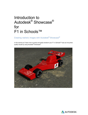
RingUsed in the Hole command to set the holediameter as well as counterbore andcountersink diameters.SphereUsed in the Hole command to set the holecenter location, in the Extrude commandto set the taper angle, and in the Sweepcommand to sweep the selected profilealong the path.When using manipulators, you do not need to keep your cursor exactly onthe 3D arrow. You can drag anywhere over empty graphics space. Manymanipulators can also snap to other geometry on your model. While amanipulator is active, you can pause your cursor over the design and promptsappear over geometry that the manipulator can snap to.Marking MenuThe Marking Menu is a spatially arranged, in-canvas menu used for executingand completing (or canceling) commands. The contents of the marking menuchange based on the context in which it is invoked.8 Chapter 1 Autodesk Inventor Fusion TP2
Marking Menu with Context MenuThe marking menu consists of eight wedges. Each wedge represents acommand/operation. These commands are the seven frequently usedcommands and the eighth is a context menu which contains additionalcommands.Marking Menu 9
The default commands in the marking menu (context menu not shown) are:1 Press Pull2 Hole3 Undo4 Context Menu5 Repeat Last Command6 Delete7 Select8 MoveYou can invoke and hide the marking menu through the following steps, To start the marking menu, right-click or right mouse down To close the marking menu, use the escape key, release the right mousebutton when no marking menu item is preselected, or click the left mousebutton when no item is selected.You can hover (pause) the cursor over an item to see the commandtip for thatcommand.10 Chapter 1 Autodesk Inventor Fusion TP2
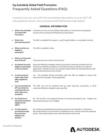
You can select an item from the marking menu through the following steps,1 Invoke the marking menu (using either the right-click or holding theright mouse down).2 Drag the cursor to the appropriate item.3 Once the cursor is over the appropriate item, release the cursor and clickthe item.The marking menu item for Move is highlighted and the commandtip for thehighlighted item is shown.Gesture BehaviorMarking Menu 11
An alternative technique to execute a command in the marking menu involvesgesture behavior. This is useful when you are well conversant with the markingmenu layout and need a faster way to execute commands. Hence before usinggesture behavior, a little practice with the marking menu to develop somemuscle memory (familiarity) around the layout of the marking menu is helpful.A gesture consists of starting the marking menu (right mouse down),immediately dragging the cursor to the location of the intended markingmenu wedge and releasing the right mouse button before the entire markingmenu is displayed. If these operations are completed within 250 milliseconds,only the selected wedge is briefly displayed to confirm that the operation wasperformed.Here are the steps for executing a gesture,1 Start the marking menu (right mouse down).2 Within 250 ms, drag the cursor in the direction of the wedge for theappropriate operation.3 Release the right mouse button.During the drag gesture, a trail is visible in the canvas, showing the cursorpath. When you release the cursor, the selected wedge is displayed for a brieftime span. The command corresponding to this wedge then gets executed.Visible train while dragging cursor in a gesture movement12 Chapter 1 Autodesk Inventor Fusion TP2
Marking menu wedge appears when cursor is releasedContext MenuThe marking menu displays a context menu in its 4th wedge. After you invokethe marking menu, drag the cursor to the appropriate operation on the contextmenu. When you release the cursor, the operation is selected.The contents of the context menu change based on the current contextdepending on, Whether modeling mode/ sketch mode is on Whether any entity is selectedMarking Menu 13
Context menu in modeling mode14 Chapter 1 Autodesk Inventor Fusion TP2
Context menu in sketching modeContext menu for Face selectionMarking Menu 15
Context menu for edge selectionThe context menu has a default menu item, which varies depending on thecontext and selection. The default menu item appears in bold text. When youselect the 4th wedge of the marking menu in a gesture movement, the defaultcontext menu item is invoked.Primary Marking Menu Behavior when a Command is ActiveWhen a command is active, certain items in the marking menu display adifferent behavior depending on the context. The 3rd wedge item whichrepresents ‘Undo when executed outside a command, now assumes Cancelbehavior within a command.16 Chapter 1 Autodesk Inventor Fusion TP2
Item no. 3 represents 'Cancel' when in mid-commandItem no 3. represents Undo outside a commandWhen a command is executing and you select a different command, thecurrent command is implicitly accepted if the input is valid. After this happensthe new command is started. This technique can be utilized for quicklyapproving a command and ending it. The seventh wedge of the markingmenu, which represents a Finish action when a command is active, is an easyway to do this. When you have provided the correct input for a commandand wish to OK it, bring up marking menu and click the Finish item toimplicitly OK the command and end it.Marking Menu 17
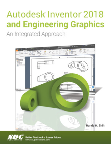
Item no 7. represents 'Finish' which can be used to commit an active commandSelection commandsMechanical designs often have many objects in the canvas which can makeselecting the appropriate object difficult.The Select Other navigation commands in Inventor Fusion help you to selectobscured or difficult-to-select geometry. The different options for the SelectOther are accessible through a glyph which can be seen when you hover thecursor over a face/edge. This face/ edge is termed as the root face/ edge.Select Other while hovering over a faceSelect Other while hovering over an edgeClick the glyph to see the fly-out menu containing the following options:1 By Depth2 Neighbor18 Chapter 1 Autodesk Inventor Fusion TP2
3 Feature4 Parent ComponentThe Parent Component option directly selects the component which is theparent for the face edge. When you select By Depth, Neighbor, or Feature, aselection strip is displayed. The strip contains several frames each representinga possible selection.When you hover over a frame in the selection strip, the corresponding elementis highlighted in the model. When you click a frame in the selection strip,the corresponding element is selected.By Depth SelectionWhen you choose the ‘By Depth selection, eligible faces/ edges/ work planes/work axes/ work points/ profiles that are partially or wholly obscured by theselected element are listed on the selection strip.Selection commands 19
In the following example, eligible faces with different depth order are listedin the selection strip.When you highlight the first frame in theZ Depth selection strip, the front mostoverlapping face element is also highlighted.The next frame selected in the strip causesan eligible element with a different ZDepth to be highlighted.Neighbor SelectionWhen you choose the Topological Neighbor selection, eligible elements thatare topologically connected to the root face/ edge are listed on the selectionstrip. For the root face, list of connected edges and edge loops is displayedwhile for a root edge a list of connected faces is displayed.20 Chapter 1 Autodesk Inventor Fusion TP2
In the following example, the topological neighbors of a root face are listedin the selection strip. The last item in the strip represents all the edge loopsconnected with the root face.When you highlight a frame in the selection strip, the corresponding edge elementis also highlighted.The last frame causes all edge loops to behighlighted.Feature SelectionWhen you choose the Feature selection, eligible feature objects that are partiallyor wholly obscured by the selected element are listed on the selection strip.Selection commands 21
In the following example, both the extrusion and the fillet are eligible features.The icons on the selection strip make it easy to identify the features by type.The icon in the selected frame in the selection strip identifies the extrude feature.The icon in the selected frame in the selection strip represents the fillet feature.Parent Component SelectionWhen you choose the Parent Component Selection, the parent componentfor the root face/edge gets selected. It is a short cut way to select the parentcomponent of an entity.22 Chapter 1 Autodesk Inventor Fusion TP2
In the following example, the parent component of the root face gets selected.The parent component option from thefly-out was selected for the root face.Consequently the parent component ofthe root face is selected.Enhanced tooltipMany of the ribbon commands have enhanced (also referred to as progressive)tooltip which display information for interaction with commands. Initially,the name of the command and a short description of the command isdisplayed. If you continue to pause the cursor, the commandtip expands todisplay additional information.Enhanced tooltip 23
Browser and Copy/PasteIn Inventor Fusion, the browser presents an organized view of the data in yourdesign. Objects selected in the browser are selected in the graphics andvice-versa. You can create new component instances in the browser. Bodiescan be dragged or copied and pasted from one component to another.1 Toggle Favorites Folder2 Toggle Information Panel3 Child Component Node4 Body Node5 Feature Node6 Pattern Node7 Occurrence Node8 Information Panel24 Chapter 1 Autodesk Inventor Fusion TP2
The blue node in the browser denotes the active component in your design.By double-clicking the component icon you can change the active component.This is important when creating new sketches, work features and features. Allnew objects that you create belong to the active component.Information PanelIn Inventor Fusion, the model information is readily available. The browserincludes an information panel for each node, which you can switch on or off.Pause the cursor over a component, body, feature, pattern, or occurrence toview information about it.Create New Component InstancesRight-click the top-level Document node and select New Component fromthe context menu to create a child component under the document. Similarly,Browser and Copy/Paste 25
right-click any component node and select New Component from the contextmenu to create a child component under the selected component.Additional Browser FunctionalitySelect Isolate Component to hide all but the selected component (UnIsolateComponent redisplays the hidden components).Use the Favorites folder to group frequently referenced components, bodies,features, and patterns.Cut/Copy and Paste bodies from one component to another, or acrossdocuments.Delete components, bodies, and features.Dissolve patterns.Cut/Copy and PasteCut / Copy and Paste offer user-interface paradigms for transferring objectsfrom a source to a destination. Cut removes the object after pasting, whereascopy keeps the source object intact after pasting. Inventor Fusion currentlysupports the following objects for cut/copy and paste: One or more pieces of sketch geometries One or more body objects One or more components (component instances) Face setsThere is no undo/redo support for the cut or copy command. Paste and pastenew are supported for undo/redo.Cut/Copy InteraceObjects can be selected from either the browser or using a graphical selection.The cut and copy commands are available from various places as follows:1 Browser: right-click a browser node26 Chapter 1 Autodesk Inventor Fusion TP2
2 Marking Menu: right-click open space3 Ribbon4 Key strokesThis functionality has also been mapped to the key sequences Ctrl Xand Ctrl C.Note: If the user uses cut, the actual cut operation does not happen until thepaste command is invoked. Every time a cut/copy command is used, thepreviously cut/copied objects are cleared from the clipboard.Paste InterfaceBrowser and Copy/Paste 27
The paste command pastes previously cut/copied objects from the clipboard.At the time of pasting a valid paste container is either deduced or needs to bespecified. Rules are as follows:1 Browser NodeOn a browser node that is a valid paste container. For example, a validpaste container for a set of sketch geometries is a sketch node in thebrowser. A component node is a valid paste container for a body or acomponent instance as long as those objects are not already includedinside the component instance.2 Graphical SelectionOn a graphical selection that is a valid paste container. For example, aface or a work plane is valid paste containers for sketch geometries.28 Chapter 1 Autodesk Inventor Fusion TP2
3 Empty SpaceWhen the paste command is invoked in empty space, the active sketchor the active component is used as the paste container if that is valid.Browser and Copy/Paste 29
4 Ribbon5 Key StrokesThis functionality has been mapped to the key sequence Ctrl V.Note: Objects can be pasted in a different document from the one they werecopied.Implicit Paste Using Browser Drag and DropIn addition, within a document, the user can drag and drop body objects andcomponent objects. These drag-and drop operations result in an implicit cutand paste.Paste New30 Chapter 1 Autodesk Inventor Fusion TP2
When a component instance is cut/copied, it can be pasted as a “shallowcopy” or as a “deep copy”. In a shallow copy, a copy of the cut/copiedcomponent instance is added to the new owner as a new component instance;the structure under it is shared with other component instances. In a deepcopy the entire subassembly under the component instance is copied.To distinguish between the two, a command called “Paste New” is availablewhen the cut/copied object is a component. Paste creates a shallow copy andpaste new creates a deep copy.Note: When a component is copied and pasted across documents, only a deepcopy is possible, so only paste new is available.Paste BehaviorWhen an object is pasted, there are two kinds of behavior depending onwhether the paste is explicit (invoked using the paste or paste new command)or implicit (invoked by drag and drop in the browser).Explicit Paste BehaviorWhen paste is done explicitly, the paste object is placed at the cursor and theuser is allowed to move it around on the screen and place it by clicking withthe left mouse button.Explicit paste does not clear the clipboard, so it is possible to repeat the paste(or paste new) command to repeatedly paste.Browser and Copy/Paste 31
Implicit Paste BehaviorWhen paste is done implicitly, this is considered a restructure operation andthe pasted object changes its place in the hierarchy. Its location and orientationin the world coordinate system remains unchanged. There is no user interactionneeded after the drag-drop.Implicit paste clears the clipboard.Make IndependentThe “Make Independent” command operates on a component instanceselection either in the browser or a graphical selection.This command makes the subassembly represented by the component instance“independent”, for example, it is equivalent to a cut followed by a deep copyof the component instance in the same parent container.There is no placement interaction when using this command, as this is alsoa “restructuring” operation.Function Key BehaviorSome keys are reserved for specific purposes in Inventor Fusion. For example,F1 accesses Help in all Microsoft Windows applications. In Inventor Fusion,many of the F-keys (function keys) are reserved for global operations.32 Chapter 1 Autodesk Inventor Fusion TP2
The following table contains all the reserved keyboard and mouse shortcutsin Inventor Fusion:Function KeyBehaviorF2PanF3ZoomShift F3Zoom windowF4OrbitF6Zoom allF7Slice graphics (see note)F10Toggle shortcut keytips in Applicationmenu and Quick Access commandbarMiddle mouse buttonPanMouse wheelZoomShift Middle Mouse buttonOrbitNote: Slice Graphics operation
Autodesk Inventor Fusion TP2 This is the Help for the second technology preview release of Autodesk Inventor Fusion released in October 2009. This content may not apply to prior or future releases. What is new in TP2? Modeling: Loft Face draft Improved move triad reorient Selective feature recognition Chamfer feature recognition Change feature .