Transcription
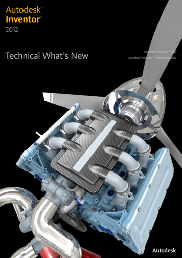
AutodeskInventor 2012Technical What’s NewAutodesk Inventor 2012Autodesk Inventor Professional 2012
Technical What’s NewContentsImproved Productivity 4Simulation Enhancements 14New, Expanded Help 4Retain Joints 14Inventor Essentials Videos 4Continuous Load Improvements 14Marking Menu 4Frame Analysis Probes 14Custom Settings Now Combined in a Single File 5Beam Model Improvements 15Enhanced Mini-Toolbars 5Customization of Beam Properties 15Dialog Boxes 5Sign Convention in Frame Analysis Results 15Select Other – Behavior Improved 6Geometry Healing and Meshing 15Dynamic Sectioning 6Guide 15Extended Feature Names 6In-canvas Tools 15High Speed Drawing Views 7Analyze Sustainability early in the Design Cycle 16Change View Orientation 7Eco Materials Adviser 16Rotate Drawing Views with Sketches 7Tooling 17Origin Mark for Ordinate Dimension Sets 7General Enhancements 17Wizard to Copy iLogic Designs 8Select Faces to Create an Insert Automatically 17Custom User Interface Formsto Automate Rules-Based Design 8Tooling Analysis Resultsin Moldflow Communicator 17Impressing Views Using New Ray Tracing Option 8Export 3D Model to Moldflow Insight 18Enhanced Modeling 9Runner Balancing 18Model Repair Tools 9Mold Base Author 182D Sketch Plane Automatically Adjusts Orientation 9Cooling Channel Check 18New Boundary Patch Command 9Cooling Channel Metric Threads 19G2 Continuity with Variable Radius Fillets 9Surface Patches with Sketch Geometryand Silhouette Curve 19Edit Alias Freeform Body 10 Mirror Fillets 10Face Draft Enhancements 10Display Failed Feature 10Boss Enhancements 11Project to 3D Sketch 11Rib Enhancements 11Sweep Along Edge 11Design View Representations in Parts 11Runoff Surface with Sketch Geometryand Silhouette Curve 19Patching and Runoff Surface Color 19User Mold Base 20Edit Moldable Part 20Transition from Part to Mold 20Multiple Locating Rings 20Define Workpiece Setting Enhancement 21Retain Last Input Value 21Improved Interoperability 12Gate Location X,Y,Z 21AutoCAD Import 12Place Plastic Part 21Updated Translators 12Ordinate Dimensions 22Rhino File Translation 12Stay Up to Date 22BIM Exchange 12Autodesk Learning and Education 22BIM Connectors 13Feedback 22OmniClass Table 13Conclusion 22Autodesk Inventor Product Line Overview 232Autodesk Inventor 2012
Technical What’s NewWelcome to the Autodesk Inventor 2012 Software Product LineEasy, Fast, OpenWe defined these three objectives for our latest generation of Autodesk Inventor products. These goals are reflected in the largenumber of enhancements in the latest version of the Autodesk Inventor product family. For you as a user, this means significantbenefits and improvements for your daily work.Autodesk Inventor 2012 sets new standards for ease of use in 3D modeling, providing the most straightforward methods of defining andmodifying parts and assemblies. Inventor 2012 removes the complexity from the CAD experience - helping you focus on the problemyou are trying to solve rather than spending time mastering techniques for creating 3D geometry and wrestling with complex dialogueboxes. Streamlined creation of advanced and compound shapes, simplified setup of simulation problems, new help and learning tools,faster and easier deployment, installation, and management for IT and CAD managers will enable you to achieve more in less time.Inventor startup times have been cut in half. Drawing view generation is up to ten times faster. iLogic design automation now allowsusers to set up iLogic models much more rapidly than in previous versions. Autodesk Inventor 2012 opens up new opportunities forsharing and updating CAD data regardless of source, complexity, or context. You can now easily accept and repair model geometrywithout worrying about the source or complexity of the model. Inventor 2012 delivers enhanced visualization and BIM-ready content,allowing you to make better sustainable design decisions and improve mold base designs.This brochure illustrates the most significant improvements in greater detail.Digital PrototypingThis year, Autodesk has packed even more value into cost-efficient software suites for your digital prototyping tasks. Autodeskcovers the entire process of digital prototyping with these suites. Since requirements are not the same at every company or in everydepartment, you will find suites with different sizes and contents.The new Autodesk Product Design Suites Premium and Ultimate replace the current Autodesk Inventor Suite and Autodesk InventorProfessional Suite packages. Customers with a current Autodesk Subscription will receive this valuable upgrade at no additional cost.Autodesk Factory DesignThe Inventor products are also included in the new Autodesk Factory Design Suites 2012 released late last year. The last page of thisdocument shows a comparative overview of features and contents of the new product suites for designers and factory planners in themanufacturing industry. The suites have been developed to meet all the needs of developers of digital prototypes and virtual plants.We want to enable you to create innovative and sophisticated high-quality products and stay ahead of the competition.Your Inventor Team3Autodesk Inventor 2012
Technical What’s NewImproved ProductivityInventor Essentials VideosNew, Expanded HelpAutodesk Inventor Wiki: OptionalThe new Help Wiki provides the most robust, relevant,and up to date information. In addition, the Wikienables you to partner with Autodesk to share yourknowledge with others. The online Help Wiki is thedefault help in Autodesk Inventor. If you are connectedto the internet when you access Help in AutodeskInventor, the Help Wiki displays. But it’s your choice:If you deployed Autodesk Inventor, and during thedeployment you disabled the Help Wiki, it is no longerthe default Help.Basic installed Help is always thereWhen you install Inventor, a subset of the help thatcontains customer favorites is installed by default.A basic Help of reference topics, tutorials for the newuser, and a What’s New are installed with the product.If you are not connected to the internet when youaccess Help in Inventor, and you did not download fullHelp, the basic installed Help displays.The Inventor Essentials Videos demonstratefundamental workflows in an illustrative and easy-tounderstand way for new users. The videos include: Overview User Interface View Navigation Part Creation Sketching Assembly Creation Drawing CreationMarking MenuFull Help downloadWhen you are not online, you can still have accessto the full Inventor Help. Download a full Help fromautodesk.com, Data and Downloads section. If you arenot connected to the internet when you access Help inInventor, and you previously downloaded full Help, thefull Help displays instead of the basic installed Help.The marking menu replaces the right-click contextmenu. You can perform a selection from the markingmenu in either menu mode or marking mode.4Autodesk Inventor 2012
Technical What’s NewMenu modeRight-click in the graphics window. Menu itemssurround the cursor and each item, or the commandname and corresponding command icon display. Todismiss the marking menu, click once again in thecenter of the menu display.Mark mode (also called gesture behavior)Draw a mark. To enter this mode, press and hold theright mouse button, and immediately move the cursorin the direction of the desired menu item. A trailfollows the cursor. Release the mouse button to selectand execute the command that corresponds to thedirection of movement of the cursor.The mini-toolbars are larger, easier to interpret, andfeature greater functionality. Mini-toolbars are addedfor the following commands: Extrude Revolve Chamfer Fillet Hole Face DraftThere are two new mini-toolbar options:Pin Mini-Toolbar PositionUse the grip button at the upper left of the mini-toolbarto move any mini-toolbar to a different location. Youcan pin the mini-toolbar so that it remains stationary inthe graphics window. Auto FadeWhen this option is enabled, if you move the cursoraway from the mini-toolbar, it displays in a minimizedstate. When disabled, the entire mini-toolbar displays,regardless of the cursor position. The marking menu helps to indicate next steps ina process and identify further options to facilitateworkflow. Additionally, it greatly reduces mouse motionand is easily customizable to suit user preferences.Dialog BoxesCustom Settings Now Combined in aSingle FilePrevious Inventor versions stored customized ribbonand keyboard settings in separate XML files. InAutodesk Inventor 2012, customization settings forthe ribbon, keyboard, and the new marking menu arestored in a single XML file. This new convention makesit easier and faster to restore customized settings whenyou install a new version of Inventor. It also facilitatessharing customized settings between differentcomputers or with other users in your organization.Enhanced Mini-Toolbars5You can now expand and collapse dialog boxes easily:To expand, click the down arrow at the top of the dialogbox. To collapse, click the up arrow at the bottom of thedialog box. This feature increases available work spacein the graphics window. It reduces mouse motion andenhances your focus on the mini-toolbar commandoptions.Autodesk Inventor 2011
Technical What’s NewSelect Other – Behavior ImprovedThe Select Other procedure in previous Inventorversions required you to hover your cursor overan object, and then click the left or right arrows totoggle between adjacent faces, edges, and features.Hovering your cursor over an object in AutodeskInventor 2012 presents you with a drop-down menulisting all available selection options. You can eliminateguesswork and speed the selection process by makingyour selection directly from the list.Dynamic SectioningExtended Feature NamesIn the Model browser, the names of part featurescan be extended with information about featureparameters. Extended feature names enable betteridentification of existing part features.To display extended feature names, on the BrowserFilters menu, select Show Extended Names.Extended feature names are displayed in the Part, SheetMetal Part, Assembly Modeling View, and Drawingenvironments.You can offset section planes in a part or assemblysection view. Right-click, and select Virtual Movement Section Plane 1 (or Section Plane 2). Then: Drag thesection plane to the desired position. Specify on offsetin the Offset dialog box. Place the cursor on the Offsetdialog box, and rotate the mouse wheel to move thesection plane.6Autodesk Inventor 2012
Technical What’s NewHigh Speed Drawing ViewsYou can now change the orientation of existing drawingviews with only a few clicks. Double-click a view, andin the Drawing View dialog box, click Change ViewOrientation. Then, in the Custom View window, specifya new view plane. When you change the orientation ofa base view, all dependent child views inherit the neworientation.Rotate Drawing Views with SketchesThe generation of drawing views is up to ten timesfaster than in the previous version through multi-coresupport. Precise views are generated in parallel byleveraging multi-core technology. You can review thedrawing or create drawing annotations before precisecalculations of drawing views finish. Precise drawingviews are calculated in the background while you workwith draft previews (raster views). Raster views aremarked by green corner glyphs in the graphic window,and by a special icon in the browser. If you place thecursor on a raster view icon, a tooltip showing theprogress of precise calculation displays.The Rotate View command is available for drawingviews that include sketches. Only sketches that areconstrained to projected model geometry rotatecorrectly with the drawing view.Origin Mark for Ordinate Dimension SetsChange View OrientationYou can override the style settingand change the origin mark forordinate dimension sets. Doubleclick the grip point next to theorigin mark. Then select a neworigin mark from the list. To changethe default origin mark for ordinatedimension sets, edit the dimensionstyle. When you change the originmark in the style, the existingordinate dimension sets with ByStyle origin mark display the new mark.7Autodesk Inventor 2012
Technical What’s NewWizard to Copy iLogic DesignsThe new version provides a wizard to copy an InventoriLogic template project. Use an Inventor iLogic projectas a template to produce design variations. Embeddesign copies as subassemblies in larger designs, oras copies of a unique and complete product definitionand save considerable time compared to the previousmethod.Impressing Views Using New Ray TracingOptionFeatures include: Selects linked documents automatically. Copy files to a new or existing project destination. Copy Inventor and non-Inventor files. Rename file copies by defining a naming prefix, suffix,or both, that can be applied globally to the copy set. Set the Part Number (iProperty) of the copydestination file the same as the copy file name. Remove iLogic rules from Inventor documentsincluded in the copied set. Use even if the documents do not involve iLogic rules.Custom User Interface Forms to AutomateRules-Based DesignRay tracing is added as a view setting option for theRealistic (default: enabled) and Monochrome (default:disabled) visual styles. If you select Realistic, thedisplay refreshes using ray tracing. You can interruptthe process with the Orbit command, after which thedisplay refreshes with ray tracing again.Design your own user interface using drag and dropmethods in a fraction of the time it took to useprogramming methods. Create a custom form to drivethe model. You can use the controls in the forms todrive changes to an existing design. Either save formdefinitions with a design document, or store them foruse across multiple documents. Create and connect thecustom user interface to the parameters, properties,and rules of an Inventor part, assembly, or drawingdocument.8Autodesk Inventor 2012
Technical What’s NewEnhanced ModelingNew Boundary Patch CommandModel Repair ToolsThe option to generate a G2 (smooth) boundary patchis added to the part modeling and repair environment.Use a G2 transition to eliminate visible seams betweensurfaces.G2 Continuity with Variable Radius FilletsImporting data often leads to deficient models dueto peculiarities of the source systems. In AutodeskInventor 2012 the problems can be solved in mostcases: Inspect and repair imported data in a repairenvironment for imported files. Then the imported datais reliable in downstream modeling operations.2D Sketch Plane Automatically AdjustsOrientationVariable radius fillets support G2 control. Use a G2transition to eliminate visible seams between faces.The View default behavior for 2D sketches is changed.When you start a sketch on a component face, theview orients so that the sketch plane normal points atthe display. The sketch plane is parallel to the display,and is ready for sketching. You can change the defaultbehavior in the Application Options.9Autodesk Inventor 2012
Technical What’s NewEdit Alias Freeform BodyLaunch Inventor Fusion from within Inventor using EditForm or Edit Copy of Form. The Edit Form commandcreates an Alias Freeform body which is then loadedinto Inventor Fusion. You can modify the body usingany of the Fusion commands then return the geometryto Inventor. Inventor Fusion now contains many ofthe commands previously available in Alias Design forInventor. These features provide technology to reshapesolid body edges and patches, transforming geometricforms to more organic ones.Mirror FilletsFace Draft EnhancementsControls are enhanced in the Draft command for addingdraft to a model. These controls speed the creation ofdraft features and make it possible to create geometrythat previously required multiple features.Create a draft feature using a parting line (2D or 3Dsketch) to position the start of the draft. Use separateangle values above and below the parting line or fixedplane. With Automatic Face Chain enabled, facestangent to the selected face are included in the draft.Automatic Blending is available for adjacent faces thatblend with a fillet or other feature. Turn on AutomaticBlending to maintain blended geometry. DirectManipulation controls are included with the Draftcommand.Display Failed FeatureFillet features can now be mirrored without includingthe parent feature. You can create symmetric modelsusing fewer features.10With Inventor 2012, you can locate failed features easilyfor problem solving. In the browser, pause the cursorover a failed feature to highlight it in the graphicswindow in its last successful state.Autodesk Inventor 2012
Technical What’s NewBoss EnhancementsWith new controls, you can create geometry in a singleboss feature that would require multiple featurespreviously.A Boss feature is placed at a point centered on themating face of the head and the thread. To change theposition of a Boss placement, in the Offset From Sketchfield, enter a value. The Angle to Fill field controls theposition of ribs on the boss feature. You can createdesigns that do not require ribs to go 360 degreesaround the boss.Rib EnhancementsThe Rib command dialog box is now enhanced withbetter organization and additional functionality. Withthe new functionality, you can create geometry that wasnot possible previously in a single feature.When creating webs (feature is extruded normal to thesketch plane), Draft and Boss tabs are available. Anoption is available to specify the thickness at the sketchor at the root of the rib feature. While you create ribfeatures, a realistic preview displays.Sweep Along EdgeProject to 3D SketchEdges of geometry are now valid selections for thesweep path. When you create the sweep feature, theedges project onto a new 3D sketch.Design View Representations in PartsWhile working in a 2D sketch, you can preview 3Dsketch geometry. The Project to 3D Sketch commandprojects geometry from the active 2D sketch and ontoselected faces to create a 3D sketch.With the command active while you modify a 2Dsketch, the new geometry displays in a preview. Afteryou finish the 2D sketch, the 3D sketch is created. Theprojected geometry is associative and updates with theparent geometry. You can disassociate the projectedgeometry by editing the 3D sketch and using BreakLink.11In part files, design view representations storeinformation related to the part view, such as partcolor, work feature visibility, and camera position. Thebrowser provides access to design view representations.Autodesk Inventor 2012
Technical What’s NewImproved InteroperabilityRhino File TranslationAutoCAD ImportSeveral new options improve interoperability withAutoCAD .On the Open flyout, select Import DWG to bypassthe Options setting. In the file import wizard, thefinal dialog box contains options to import AutoCADSurfaces and Wires. To enable the Surface and Wireselection, select New Part. Materials applied inthe AutoCAD file persist in the Inventor file aftertranslation.Updated TranslatorsThe following translators support newer versions of thefile format:CATIA V5 Import: R6 - R20 Export: R10 - R19Rhino (*.3dm) files can be imported for use in AutodeskInventor. The import operation does not maintainassociativity with the original file. After the importoperation: Changes to the original file do not affect theimported part. Changes to the imported part do notaffect the original file. You can change the model as if ithad been created in Autodesk Inventor. Use the Repairenvironment to heal models and fix surfacing errors.BIM ExchangeGeneral ImprovementsIf you are working frequently with colleagues inthe various building fields, these new features areimportant for you. Inventor 2012 provides severalintegration improvements for BIM (BuildingInformation Modeling) Exchange: iPart and iAssemblytable access allows you to change between members.Export of Building Components makes data exchangeeasier. Connector access and workflows are improved.The various changes are outlined in the following.ParasolidImport: up to version 23.0 Export: versions 9.0 - 23.0 NXImport: versions 3 - 7.5 12Autodesk Inventor 2012
Technical What’s NewExport Building ComponentsBefore you export the component, provide all inputsand selections, and then click Apply Changes. To exclude model properties, clear the ModelProperty check box. When Model Property is selected,model properties are exported with the component. The model orientation options include ViewCube. TheViewCube „views“ generate component views whenexporting. When the model is opened in Revit, theViewCube positions sync with the Revit ViewCube. To redefine the ViewCube origin point, use the triad.Select a component vertex or work point as input forthe origin point. Thumbnail images are the isometric view of eachorientation option. Each orientation option has anassociated image. The images reflect what you see inthe display. Use View settings for shadows, groundreflections, and lighting to produce a high qualitythumbnail image. onnector parameters are included in the DesignCCheck and display an icon and are colored red wheninvalid. If you use Export Building Componentswithout doing the Design Check, it is runautomatically and reports any invalid connectorparameters. The connector browser icon updates tonote the invalid connector. Suppressed connector nodes and text display theirsuppressed state. Exported connector parameters are accessible in theiPart Author and can be used as keys in the iPart oriAssembly. Promote Component Connectors enables exposingthe sub-component connectors in the parentassembly. Connector links are not promoted, butcan be added. Promote Component Connectors isaccessible from the connector folder browser nodecontext menu. After promoting connectors, you can excludeindividual connectors by unselecting Include in thecontext menu. From a promoted connector you can locate and selectthe Source Component via the context menu. Thesource component is selected and highlighted. Promoted connectors are included in the DesignCheck. OmniClass TableBIM ConnectorsSeveral improvements have been made to BIMconnectors. The connector improvements include: Parameters use Inventor unit formatting. Parameter values can be included in the parameterstable by checking the box in the fx column. For numeric parameters, the Inventor fly out menu isadded providing access to Measure, Show Dimension,List parameters, and Most Recently Used (MRU)options. Parameters that are identified for export in the modelparameter table are included in the export buildingcomponent process. Inventor size parameters are associated with theRevit Length type.13OmniClass is a classification scheme of internationalorganizations (ISO and ICIS) for the building industry. Itis under development since 1990. The new OmniClassTable dialog box provides an improved means oflocating the Revit class for your BIM content. Revit andAME MvPart types are synchronized. A Look in optionis available to refine category filtering. Table contextmenu options control column display.
Technical What’s NewSimulation EnhancementsFrame Analysis ProbesRetain JointsWhen joints are built automatically from assemblyconstraints, you can retain them in the model whenthe translator is turned off. You have the opportunityto both customize the standard joints built fromconstraints and author new standard joints, withoutstarting from scratch.New Probe and Probe Labels commands enlarge the listof tools for viewing simulation results. The commandshelp you to: Create probes for selected simulation results. Control the visibility of probe label in the graphicswindow.You can create one or more probes when any simulationresult is active, and then switch between results tosee values. Run the simulation, select Probe, and clicka node or any position on the beam in your model.Created probe annotations are displayed when anyresult is active. Click Probe Labels to toggle the probevisibility.Continuous Load ImprovementsEnhancements are added to help you define the startand end magnitudes of the continuous load. Placementoptions are expanded with relative and absolutedefinition of offset.In the Frame Analysis environment: Define the end magnitude as well as the startmagnitude of the continuous load. The Checked Custom size option enables you tospecify the offset and length of the load on theselected beam. Define offset using the absolute or relative values.14Autodesk Inventor 2012
Technical What’s NewBeam Model ImprovementsYou can edit an increased number of beam mechanicalproperties, including two new properties:Reduced Shear Stress (Ax) and Reduced Shear Area(Ay).At the bottom of the Beam Properties dialog box, checkCustomize, and then enter your values. It allows you tofully define, or control the section properties.Sign Convention in Frame Analysis ResultsStress results were unified to use the same signconvention as the Stress Analysis results. Theinterpretation of Frame Analysis results is nowconsistent with Stress Analysis results.Geometry Healing and MeshingIn the Frame Analysis Settings dialog box, Beam Modeltab, two options are added:Create Rigid LinksWhen selected, you are increasing the flexibility toadjust the beam model during automatic conversion.When the check box is cleared, rigid links are notautomatically created during model conversion.Instead, you can create rigid links manually accordingto your needs and preferences.Trim Mitered Beam EndsWhen you select this option, the overlaps are trimmedduring automatic model conversion. It simplifies thegenerated model and improves the accuracy of thesimulation results.Customization of Beam PropertiesEnhancements in the geometry healing and meshingoperations for stress analysis mean increased success inanalyzing complex designs.In consumer products and some other industries,product designs involve many surfaces and tighttolerances. You can simulate the behavior of suchdesigns before you build a physical prototype.GuideThe improved content and interface in the StressAnalysis Guide help you to find the answers you need,whether your skills are novice or intermediate.In-canvas ToolsNew Marking Menus are present in all Simulationenvironments. These menus provide immediate accessin the canvas to the most commonly used c
Technical What's New 3 Autodesk Inventor 2012 Welcome to the Autodesk Inventor 2012 Software Product Line Easy, Fast, Open We defined these three objectives for our latest generation of Autodesk Inventor products These goals are reflected in the large number of enhancements in the latest version of the Autodesk Inventor product family For you as a user, this means significant
