Transcription
Chapter 1IBCM: The Itty Bitty Computing MachineThe child receives data through the sense organs; the child also has some inborn processing capacities –otherwise it would not be able to learn – but in addition, some “information” or “programs” are built-inat birth . . . there is a working memory . . . and there is a permanent memory . . . so there must be someinner “language” or medium of representation . . . Jerry Fodor . . . has discussed this inbuilt “languageof thought,” which is similar conceptually to the “machine language” that is built into the personalcomputer.– John Cleverly, in “Visions of childhood: Influential models from Locke to Spock” [3]1.1IntroductionMachine language, or machine code, is the set of instructions that a computer’s central processing unit(CPU) understands. It is the binary 0’s and 1’s that form instructions for the CPU to execute. When wecompile a program, that program is eventually converted to binary machine code, which we can then run.Each different CPU has a different machine language that it understands, although CPU families tend tounderstand a very similar language.Programming in machine language requires one to write the code in hexadecimal notation, manuallyencoding the instructions one at a time. For this reason, machine language can often be difficult to program in. This is especially true with the complexities of modern instruction sets on processor familiessuch as the x86 and MIPS.One will often write a program in assembly language, which is a (somewhat) higher-level manner tocreate a program. In assembly language, one can specify to add two values together through a commandsuch as sub esp, 24, and need not write it in the hexadecimal notation of 0x83ec20. An assembler isa program that converts assembly language into machine language. In fact, compilers typically produceassembly language, and then call the assembler to produce the machine code.Learning how machine language works allows us to truly understand how a machine operates at avery low level.In this chapter we introduce a simplified machine language called the Itty Bitty Computing Machine,or IBCM. This machine language is designed to be simple enough that it can be learned in a reasonableamount of time, but complex enough that one can use it to write a wide range of programs. It is intendedto teach many of the important concepts of a modern machine language without having to deal with the1
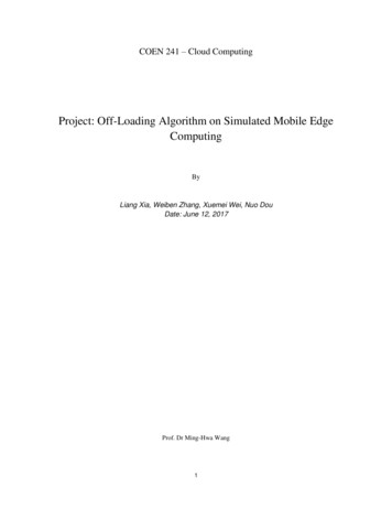
2CHAPTER 1. IBCM: THE ITTY BITTY COMPUTING MACHINEcomplexities of – and time required to learn – modern CPU machine languages.1.2Memory HierarchyTypically, computer programs do not differentiate between the various levels of memory. Programs tendto view memory as a monolithic whole, and allocate memory as needed. In fact, there are many differentlevels of memory. Fast memory – formally called static random-access memory or SRAM – is expensive tomake, and computers would be quite expensive if all memory were fast memory. In fact, some supercomputers did just this – the Cray Y-MP, a super computer from the late 1980’s, used only SRAM, and itcost approximately 10 million dollars.Instead, most computers use primarily dynamic random-access memory, or DRAM, as the primarycomponent of main memory, and use a smaller amount of SRAM to speed up computations. SRAM isused in the cache, although we will not go into detail about caches here.The four primary levels of memory arelisted below. Cost decreases and storage capacity increases as one moves down the list. CPU registers Static random-access memory (SRAM)in various levels of cache (L1 cache, L2cache, etc.) Dynamic random-access memory (DRAM)used in main memory Hard drive storage, either on a traditional hard disk with rotating platters,or on solid state hardware.This chapter will largely ignore storingdata in cache or on the hard drive, as that istypically managed by the operating system.Instead, we will primarily focus on the valueskept in the registers in a CPU, and in mainmemory.Figure 1.1: Memory HierarchyMain memory is relatively slow, compared with the speed of a CPU. In addition, many CPUs can only allow one memory access per instruction. Thus, the other values must be kept in a location that is not main memory: the CPU’s registers. Aregister is a small area of memory in the CPU where intermediate computation values can be stored. Amodern CPU will have registers that each are 32 or 64 bits in size, and may have 12-32 of these registers.Thus, there are instructions – in both machine language and assembly language – that move databetween the CPU’s registers and main memory. We will see these instructions shortly.
1.3. IBCM PRINCIPLES OF OPERATION1.31.3.13IBCM Principles of OperationMachine DescriptionThe Itty Bitty Computing Machine (IBCM) is a very simple computer. In fact, it’s so simple that no onein their right mind would build it using today’s technology. Nevertheless – except for limits on problemsize – any computation that can be performed on the most modern, sophisticated computer can also beperformed on the IBCM. Its main virtues are that it can be taught quickly and provides context for talkingabout more recent architectures.The IBCM contains a single register, called the accumulator. Most early computers had just an accumulator, and many current micro-controllers are still accumulator machines. IBCM’s accumulator canhold a 16-bit 2’s complement integer. In addition, the IBCM has two other registers: the instruction register (IR), which contains the current instruction being executed, and the program counter (PC), whichcontains the address of the next instruction to be executed. However, we will not directly use those tworegisters.The IBCM has 4,096 addressable memory locations and each of these locations holds 2 bytes (16 bits).Thus, the IBCM technically has 8,192 bytes (8 Kb) of memory.The IBCM handles input by reading in single values (either a hexadecimal value or an ASCII character)into the accumulator. Similarly, output is handled by writing the value in the accumulator as either ahexadecimal value or an ASCII character.1.3.2InstructionsThe IBCM equivalent of “statements” in a higher level language are very simple instructions. Each instruction is encoded in a 16-bit word in one of the formats shown in Figure 1.2. Shaded areas in the figurerepresent portions of the instruction word whose value does not matter. For example, a word whoseleftmost four bits are zero is an instruction to halt the computer.bit:15141312000000010010opcode11 ntaddressshiftsothersFigure 1.2: IBCM instruction formatA note on using hexadecimal notation: IBCM is a binary computer. Internally all operations are performed on 16-bit binary values. However, because it’s so tedious and error-prone for humans to write orread 16-bit quantities, all of IBCM’s input/output is done either as ASCII characters or 4-digit hexadecimal numbers. Remember that these are just external shorthands for the internal 16-bit values!Also, hexadecimal values are often prefixed by a ’0x’, such as ’0x1234’.
4CHAPTER 1. IBCM: THE ITTY BITTY COMPUTING MACHINEHaltAny instruction where the opcode is zero (i.e., the first 4 bits are all zero) will halt the IBCM. It does notmatter what the remaining 12 bits are. Not much else to say on this one.Input and OutputThe input and output (or ’I/O’) instructions move data between the accumulator and the computer ’devices’ – the keyboard and screen. Data can be moved either as hexadecimal numbers or as an ASCIIcharacter; in the later case, only the bottom (least significant) 8 bits of the accumulator are involved. Thenext two bits after the opcode specify if the instruction is an input or output, and if it will use hexadecimal values or ASCII characters. The four possibilities (in/out, hex/ASCII) that are specified by the bits11 and 10 of the instruction word as shown in Table 1.1. Being as there are only four possibilities, the fullhexadecimal encoding of each of the four I/O instructions is also listed.bit 110011bit 100101operationread a hexadecimal word (four digits) into the accumulatorread an ASCII character into the accumulator bits 8-15write a hexadecimal word (four digits) from the accumulatorwrite an ASCII character from the accumulator bits 8-15hex value0x10000x14000x18000x1c00Table 1.1: IBCM input/output bit valuesShifts and RotatesShifting and rotating are common operations in computers. Shifting means moving data to the right orleft; rotating is much the same thing except that bits that “fall off” one end are reinserted at the other end.The examples below assume that the value being rotated is one byte (8 bits) in length. In reality, theIBCM performs shifts and rotates on the 16 bit value in the accumulator. We choose to describe theseoperations with 8 bit quantities to make the explanation easier to understand.Diagrammatically, a “right shift” of “n positions” looks like Figure 1.3 when n 3:Original0 1 0 0 1 1 1 0Shifted0 0 0 0 1 0 0 1 1 1 0Figure 1.3: A right shift of 3Each bit is moved n positions to the right (three in this case). Alternatively, it is moved one bit to theright n times. This causes the original n right-most bits to fall off the right end and n new (zero) bits tobe inserted at the left end. A “left shift” is much the same, except that bits move to the left, as shown inFigure 1.4.
1.3. IBCM PRINCIPLES OF OPERATION50 1 0 0 1 1 1 0Original0 1 0 0 1 1 1 0 0 0 0ShiftedFigure 1.4: A left shift of 3As noted previously, rotates are like shifts except that the bits that fall off one end but are reinsertedat the other end. Figure 1.5 is a left rotation; right rotates are left to your imagination.Original0 1 0 0 1 1 1 0Shifted0 1 1 1 0 0 1 0Figure 1.5: A left rotation of 3Note that the shift instructions uses bits 11-10 to specify the shift operation. The first bit specifies if itis a shift (0) or rotate (1), and the second bit specifies if it is moving left (0) or right (1). This is shown inTable 1.2.bit 110011bit 100101operationshift leftshift rightrotate leftrotate rightTable 1.2: IBCM shift/rotate bit valuesIn addition, bits 3-0 of the shift instructions specify the “shift count” – that is, the number of bitspositions that the data is to be shifted (or rotated).A left rotate of 3, which is what is shown in Figure 1.5, would have the opcode set to 2 (binary 0010),the shift/rotate bit set to 1, the left/right bit set to 0, and the shift count set to 3. The encoded instruction,in binary, is shown in Figure 1.6. Note that the grayed-out part of the table are the bits whose value doesnot matter; we set them to iftcount 0x2803Figure 1.6: IBCM instruction for a right rotate of 3As shown in the table, the hexadecimal encoding of the instruction is 0x2803.
6CHAPTER 1. IBCM: THE ITTY BITTY COMPUTING MACHINEOther InstructionsAll other bit combinations in the left-most four bits either specify an arithmetic instruction or a controlinstruction – similar to assignment statements and gotos in a high level language. The first four bits arecalled the “op” field of the instruction; the value of this field is often called the “opcode”. The “address”portion of the instruction generally specifies an address in memory where an operand (variable) will befound.There are 13 IBCM operations of this form – eight that manipulate data and five that perform control. The data manipulation operations all involve the “accumulator” and typically data from a memorylocation is specified by the address portion of the instruction (the not and nop instructions are the onlytwo different ones). The result of data manipulation operations is recorded in the accumulator. Thus, the“add” instruction forms the arithmetic sum of the present contents of the accumulator with the contents ofthe memory location specified by “address” and puts the result back into the accumulator. Thus, it is similar to the primitive assignment statement “accumulator accumulator memory[address]”.The control instructions determine the next instruction to be executed. The “jump” instruction, forexample, causes the next instruction executed to be the one at the location contained in its address field.If you think of the address of a memory cell like a label in a high level language, then jump is just “gotoaddress”.Two of the control instructions are conditional; they either cause a change in the control flow or not,depending on the value of the accumulator. The simplest of the control instruction is nop; it does nothing.Table 1.3 describes the function of each of these 13 IBCM instructions; both English and programminglanguage-like explanations are given for each instruction. In the latter, “a” is the accumulator, “addr” isthe value of the address portion of the instruction, and “mem[]” is ike meaninga : mem[addr]mem[addr] : aa : a mem[addr]a : a – mem[addr]a : a & mem[addr]a : a mem[addr]a : a mem[addr]a : agoto ‘addr’if a 0 goto addrif a 0 goto addrbranch and linkEnglish explanationload accumulator from memorystore accumulator into memoryadd memory to accumulatorsubtract memory from accumulatorlogical ‘and’ memory into accumulatorlogical ‘or’ memory into accumulatorlogical ‘xor’ memory into accumulatorlogical complement of accumulatordo nothing (no operation)jump to ‘addr’jump to ‘addr’ if accumulator equals zerojump to ‘addr’ if accumulator less than zerojump (branch) to ‘addr’; set accumulator to the value of thethe “return address” (i.e., the instruction just after the brl)Table 1.3: IBCM opcodesA few words of additional explanation are necessary for some of these operations, all of which arefairly standard for most computers.1. Arithmetic operations may “overflow” or “underflow”; that is, the magnitude of the result maybe larger than can be represented in 16 bits. The programmer is responsible for ensuring that this
1.4. SAMPLE PROGRAM7doesn’t happen.2. The logical operations (and, or, xor, and not) perform bit-wise operations on the operands. TheBoolean operations themselves are shown in Figure 1.7.and01000101or01001111xor01001110not0110Figure 1.7: Boolean operation reference3. The not instruction only inverts the bits in the accumulator, and does not use a memory location;the ’address’ part of the instruction is ignored.4. Likewise, the nop instruction ignores the ’address’ part of the instruction.5. The branch and link instruction is used for subroutine calls, as discussed later.1.3.3Other opcodesWhen writing an IBCM program, one will typically write out the IBCM opcodes, such as add and store.There are a few other opcodes that are not listed above, but that will often appear in an IBCM file: 1.4dw (for “declare word”), for declaring variablesreadH and printH are for reading or writing a hexadecimal valuereadC and printC are for reading or writing an ASCII charactershiftL and shiftR are for the shiftsrotL and rotR are for the rotationsSample ProgramConsider the IBCM program shown in Listing 1.1. This program does not compute a useful result; that’scoming next. Instead, it is intended to show how the IBCM works. Address000001002003004005006 ddsubornotstorebrlAddress000000001003N/A000000 Listing 1.1: Sample IBCM programLet’s trace what this program does. All the values below are in hexadecimal. All addresses are represented using three digits.
8CHAPTER 1. IBCM: THE ITTY BITTY COMPUTING MACHINE1. Address 000: Instruction value 3000. Opcode 3 is a load, with an address of 000. This will load thevalue in memory at address 000 into the accumulator. The value in address 000 is 3000 – it is boththe instruction being executed and the data being loaded. The accumulator is now 3000.2. Address 001: Instruction value 5000. Opcode 5 is an add, with an address of 000. This will add thevalue in memory at address 000 to the accumulator, and store the result in the accumulator. Thevalue in address 000 is 3000, so the result (and the new accumulator value) is 6000.3. Address 002: Instruction value 6001. Opcode 6 is a sub, with an address of 001. This will subtractthe value in memory at address 001 from the accumulator, and store the result in the accumulator.The value at address 001 is 5000; 6000-5000 1000. Thus, the new accumulator value is 1000.4. Address 003: Instruction value 8003. Opcode 8 is an or, with an address of 003. This will perform abit-wise or’ing of the value in memory address 003 with the value in the accumulator, and store theresult in the accumulator. The value in address 003 is 8003 – again, we are using the same value forthe instruction being executed and for the data being used.To perform a bit-wise logical operation, write out the full bit values for each of the operands, andperform the bit-wise operation (or, in this case) on each of the bits in each column. 0x80030x1000 100000011001000000000000000000000000001100000011 0x9003Thus, the value in the accumulator is 9003.5. Address 004: Instruction value a000. Opcode a is a not operation. This opcode ignores the addressportion of the instruction, as the operation just inverts all the bits of the accumulator. The bit valueof the accumulator prior to the not operation is listed in the previous step. 0x9003 10010110000011110000111100111100 0x6ffcThus, the value in the accumulator is 6ffc.6. Address 005: Instruction value 4000. Opcode 4 is a store instruction, with an address of 000. Thiswill store the current value in the accumulator (6ffc) into memory at address 000. The previousvalue in that spot (3000) is, of course, overwritten.7. Address 006: Instruction value f000. Opcode f is a brl (branch and link) instruction, with address000. This will store the address of the next instruction (i.e., the address after 006, or 007) in theaccumulator, and jump to the specified address of 000. Thus, the value in the accumulator after thisinstruction is 0007, and the next instruction to be executed is address 000.8. Address 000: Instruction value 6ffc. Note that this value was written to memory two steps prior (theinstruction at address 005), and control jumped to this instruction from the previous instruction (theinstruction at address 006). Opcode 6 is a sub, with address ffc. As all values in IBCM’s memory areinitialized to zero, the value in address ffc is thus zero. Thus will subtract zero from the accumulatoryielding the original value of 0007, which is what is stored in the accumulator after this instructionis executed.Program control will continue. The next time the accumulator executes the instruction at address 005(instruction value 4000; opcode 4 is a store), the value written to address 000 will be 5ffc (opcode 5 is an
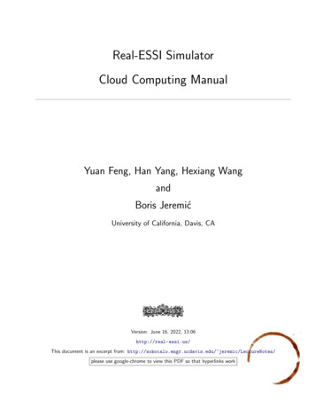
1.5. THE IBCM SIMULATOR/DEBUGGER9add). The next time around, it will write 6ffc (opcode 6 is a sub). Thus, this program will loop forever,alternately writing 6ffc and 5ffc to address 000 at the end of each loop.One of the important points to note in the above program is that the distinction between data andinstructions is blurred. The value 6ffc is computed through a series of instructions, and then stored –as data – at address 000. But when the program control reaches that point, the value of 6ffc – that waspreviously data – now becomes an instruction.We will see additional examples of using data as instructions, and using instructions as data, in theexample programs section, below.1.5The IBCM Simulator/DebuggerTo run an IBCM program, you can viewthe online simulator at http://libra.cs.virginia.edu/ibcm [2]. The instructions listedin this section are also listed at that website. Animage of the online emulator is shown in Figure 1.8.The simulator reads in text files, and proceedsto simulate the result of an IBCM program execution.To load a file, use the Browse button at the topof the simulator page. Find the IBCM file, andclick on the “Load” button. The format of yourprogram file is very rigid – the first four characters of each line are interpreted as a hexadecimalnumber. The number on the first line is loadedinto location zero, the next into location one andso on. Characters after the first four on each lineare ignored, so you should use them to commentthe code. Blank lines are not allowed, nor are linesthat do not start with four hexadecimal digits (i.e.,no ’comment’ lines). An invalid file will either notload up at all, or will load up gibberish.Figure 1.8: Web-based IBCM interfaceThe left side of the simulator lists all the memory locations (using the hexadecimal address), thevalue in memory (if any), and the PC (program counter) value. Note that any blank value field is interpreted as’0000’, as per the IBCM specification. When first loaded, the simulator may uninitialized valuesblank to increase readability.The value column consists of a series of text boxes, which allow you to directly edit the values in memory. The simulator will read the current memory location from the appropriate text box when executingan instruction. You can undo any edits by using the Revert button, described below. The IBCM simulatordoes not check to ensure that your entered values are valid – it is up to the user to do this. Note that allhexadecimal values must be 4 digits (i.e. ’0000’, not ’0’), or else the simulator may not function correctly.Be sure to read the section about crashing browsers and losing your work, below. There is no way to save
10CHAPTER 1. IBCM: THE ITTY BITTY COMPUTING MACHINEyour edited work – you will need to copy the changes by hand. This is party due to a browser limitation,and partly due to the fact that memory editing is meant to be a debugging tool, not a means to write entireIBCM programs from scratch.The ’PC’ column lists the current value of the program counter. It can have three values. Normally,it will have a left pointing arrow (’ -’), which indicates the next instruction that will be executed. If thesimulator is waiting for input, it will have a capital ’I’ (for Input) next to the input instruction that iscurrently awaiting a value – and the “Input” text on the right side will blink. Lastly, if the program hashalted, then a capital ’H’ (for Halt) will be displayed next to the halt instruction that was executed.On the right side, the values of the accumulator and program counter are listed, both in hexadecimalnotation. As mentioned above, the PC field will also display, on the left side next to the hexadecimaladdress, if the simulator is awaiting input or is halted. The Input box is used to read in user input whena program requests it. When the simulator is waiting for input, it will flash the ’Input’ text. In addition,the simulator will specify which type of input is being requested: ’hex’ or ’asc’ for hexadecimal or ASCIIinput, respectively. Note that for entering a hexadecimal value, you do not need to enter all 4 digits: i.e.,you can enter ’12’ instead of ’0012’. This is distinctly different that editing memory locations (you have toenter all 4 digits for those). If you enter multiple characters for ASCII input, it will only read in the firstone.Below this are four buttons. Two control execution: Run, which will start a program executing, andStep, which will execute a single instruction. Note that Run will execute until either a halt command isreached, or until an input command is reached. The other two buttons control the resetting of the IBCMprogram. The Reset button will reset the PC and accumulator, in effect allowing the program to run again.It will not, however, modify any memory locations. The Revert button will do what a Reset does, but willalso revert the memory locations to what they were when the file was last loaded; it does not load thefile from disk again. Thus, if you have edited any of the memory locations (or the IBCM program hasmodified them), then those changes will be erased on a Revert, but not on a Reset. Note that a Revert willnot modify memory addresses outside the range that was loaded (i.e. any ’blank’ values).Any output is displayed in the text area below these buttons. Each output command prints the value(hexadecimal or ASCII character) on a separate line.A few notes: You will notice a slight delay when loading the simulator page. This is due to the fact that a numberof scripts are run when the page loads (to initialize the memory table of 4096 elements, for example),and this takes a bit of time. How long this takes is determined by how fast a computer it is runningon, as the scripts are run on the client side. Upon entering input, hitting Enter is considered the same as hitting the Run button again. If youonly want to execute a single instruction after an input, you must click on the Step button. The simulator does minimal error checking with the input from the keyboard during program execution – it is the user’s responsibility to ensure that the input is properly formatted. The only errorchecking that is done is to ensure that a non-empty string was entered (if it was, then the simulatorwaits for more input). Because of the limitations of threads running in web browsers, there is no way to terminate a program that is stuck in an infinite (or very long) loop – the browser will not allow a polling (checking)to see if a Stop button was pressed, for example. Some browsers will pause the script after a minute
1.6. WRITING IBCM PROGRAMS11or so of execution, and ask if the user wants to continue. Alternatively, you can close the webbrowser and restart. Note that this means if you have edited any of the memory locations, and yourbrowser hangs or is restarted, you will lose any and all changes you have made to the memorylocations! The simulator page is a PHP script, which means that it will not work if you are viewing it as a localfile (if the beginning of your URL is “file://” instead of “http://”), or if the web server hosting thispage does not have PHP installed (this latter restriction includes UVa’s Collab web server). Browser compatibility: It has been tested in Internet Explorer under Windows, Safari under Mac OSX, and Firefox under Windows, Mac OS X, and Ubuntu Linux. Note that the display of the changingof the values as the simulation is run (the PC, memory values, etc.) will only work on some browser/ operating system combinations (Firefox, in particular, works well for this). The other browserswill have the same end state after the program is run, but will not animate the execution of theIBCM program when ’Run’ is pressed (the ’Step’ command will still animate each step). The format of your program file is very rigid – the first four characters of each line are interpretedas a hexadecimal number. The number on the first line is loaded into location zero, the next intolocation one and so on. Characters after the first four on each line are ignored, so you should usethem to comment the code; example code will be discussed in class. When you execute a halt, the simulator will halt with the PC pointing at the halt.1.6Writing IBCM Programs1.6.1Complex control structuresThe control structures that we are familiar with in higher level languages can be implemented in IBCM, albeit with a bit more effort.Consider a typical pseudo code if-then-else conditional shown in Listing 1.2 to the right.The IBCM code for this conditional is shown in Listing 1.3. Because we do not know many of the required addresses (of variable B,or where S1 and S2 start in memory), we have chosen to leave it in assembly format (i.e., using opcodes) rather than provide machine code.If we wanted to compare B to a different value, such as 5, we wouldhave to load B into the accumulator, subtract 5 from that, and thenperform a jmpe or jmpl. This is illustrated further below, when discussing the while loop.Presumably, the ellipses at labels S1 and S2 would have some set ofIBCM opcodes to execute.Loops are also easily converted to IBCM. Note that a for loop isjust a while loop, but with a statement performed before the loopstarts (the “for init”), and a statement performed at the end of eachloop iteration (the “for update”). Consider a straight forward whileloop shown in Listing 1.4. i f ( B 0 )S1 ;elseS2 Listing 1.2: if pseudo code load Bjmpe S1S2 : . . .jmp done ;S1 : . . .done : . . . Listing 1.3: IBCM if code while ( B 5 )S; Listing 1.4: while pseudo code
12CHAPTER 1. IBCM: THE ITTY BITTY COMPUTING MACHINEWe cannot directly compare a variable to the value 5; we can onlycompare it to zero via the jmpe and jmpl instructions. Our IBCM codeis shown in Listing 1.5.If B 5, then we want our loop to terminate. If B 5, thenB 5 0, so we will execute a jmpl to break out of the loop. If B 5,then B 5 0, and we will continue in the loop. loop : load Bsub f i v ejmpl doneS: .jmp loopdone : . . . 1.6.2 Listing 1.5: IBCM while codeGeneral tipsWhen writing IBCM programs, we recommend these steps:1. Write the pseudo code first – or even actual code – to make sure your algorithm works as desired.If you have a bug in the design of your algorithm, then you will never get your IBCM code to work.2. Write the program using IBCM opcodes, so that it looks like assembly: add one, store x, etc.Comment this clearly!3. Trace this assembly code, by hand, from beginning to end. It will be far easier to find a bug in yourprogram in the assembly stage than in the hexadecimal code stage.4. Finally, translate it to machine code, and run it in the simulator.We cannot stress enough how important it is to first make sure that the algorithm works, then to writeand trace the assembly versions of the program. Debugging hexadecimal machine code is not much fun.1.7Example ProgramsWe present a number of IBCM example programs to help you get acquainted with the language.1.7.1SummationThe first program will compute the sum of the integers1 through n, where n is read from the keyboard; theresulting sum is printed to the screen. The
Fast memory - formally called static random-access memory or SRAM - is expensive to make, and computers would be quite expensive if all memory were fast memory. In fact, some super computers did just this - the Cray Y-MP, a super computer from the late 1980's, used only SRAM, and it cost approximately 10 million dollars. Instead, most computers use primarily dynamic random-access .