Transcription
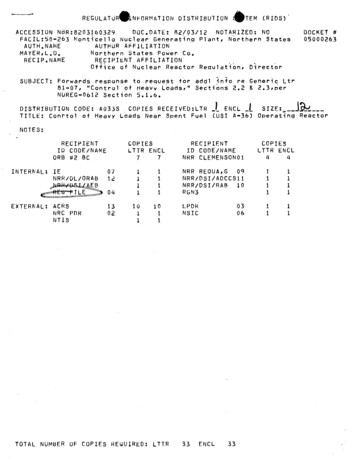
REGULATURONFORMATION DISTRIBUTION *TEM(RIDS)ACCESSION NBR:8203160329DOC,0ATE: 82/03/12 NOTARIZED: NOFACIL:50-263 Monticello Nuclear Generating Plant, Northern StatesAUTHOR AFFILIATIONAUTHNAMEMAYER,L.O,Northern States Power Co.RECIPIENT AFFILIATIONRECIP.NAMEOffice of Nuclear Reactor Regulation, DirectorDOCKET #05000263SUBJECT: Forwards response to request for addi info re Generic Ltr81-07, "Control of Heavy Loads," Sections 2.22.3,perNUREG-0612 Section 5.1.6.DISTRIBUTION CODE: A033STITLE:ENCLSIZE: .j.(USI A-36) Operating ReactorCOPIES RECEIVED:LTR IConrto1 of Heavy Loads Near Spent FuelNOTES:RECIPIENTID CODE/NAMEORB #2 BCINTERNAL:EXTERNAL:77RECIPIENTID CODE/NAMENRR CLEMENSON012,1111111COPIESLTTR ENCLIENRR/DL/ORABEBILE0712ACRSNRC PDRNTIS13020410111011TOTAL NUMBER OF COPIES REQUIRED: LTTRCOPIESLTTR ENCL44NRR PORNSIC1111330306ENCL33
'4.Northern States Power CompanyCMarch 12, 1982DirectorOffice of Nuclear Reactor RegulationU S Nuclear Regulatory CommissionWashington, D C 20555MONTICELLO NUCLEAR GENERATING PLANTDocket No. 50-263 License No. DPR-22Control of Heavy Loads (Unresolved Items)Attached are responses to sections 2.2 and 2.3 ofEisenhut's letter dated December 22, 1980, titledLoads." The January 12, 1982 response identifiednot been resolved. Attached are the responses toEnclosure 3 of Mr"Control of Heavytwo items that hadthese open items.This completes our response to Mr Eisenhut's December 22, 1980 letter.L 0 Mayer, PEManager of Nuclear Support ServicesLOM/TMP/bdAttachmentcc:Regional Admin-III, NRCNRR Proj Mgr, NRCNRC Resident InspectorG Charnoff8203160329 820312PDR ADOCK 05000263PDR
ATTACHMENT AResponse to Request for Informationin Section 2.2.3 of NRC Generic Letter 81-07NRC QUESTION 2.2.3Identify any cranes listed in 2.2.1 which you have evaluated as havingsufficient design features to make the likelihood of a load drop extremelysmall for all loads to be carried and the basis for this evaluation (i.e.,complete compliance with NUREG-0612, Section 5.1.6 or paritial complianceForsupplemented by suitable alternative or additional design features).each crane so evaluated, provide the load-handling-system (i.e., craneload-combination) information specified in attachnent #1.5.(Attachnent 1) Provide an evaluation of the interfacing lift points withrespect to the guidelines of NUREG 0612, Section 5.1.6.RESPONSEWe have completed a review of the interfacing lift points per NUREG 0612,section 5.1.6 for heavy loads handled by the reactor building crane. Theresults of this review are shown in Table I. We are proceeding with designmodifications of interfacing lift points that do not meet the criteria specified in NUREG 0612 section 5.1.6. Table II lists the items associated withthe Reactor Building Crane not evaluatel and the reason for not evaluatingthem.RKRA-1
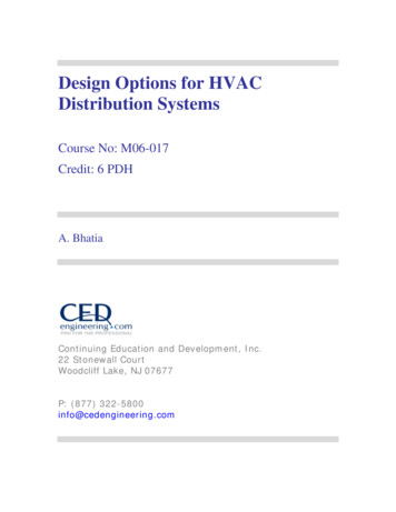
0ATTACHMENT AControl of Heavy LoadsInterfacing Lift Point Review ResultsTable IPage 1 of 2ItemNo.EquipmentWeight(Kips)/Slingangle (1)Designload(Kips)(2)Mat' tyFactorMeet NRCDesignCriteriaYesNo0.9Vessel Service Platform6/0012A-36/58Stud Detentioner Carousel20/0040A-36/58 (3)x54.0Fuel Pool Shield Blocks10/0020A-36/58x39.0RPV Head90/00180A-533/80x7.5Drywell Head80/00160A-212/80x7.5A-36/58x4.8A-36/58 (3)x10.588A-36/58 (3)x7.860A-36/58 .5xA-36/58x5.2xA-36/58 (3)x9.4xA-36/58 (3)x1.6Fuel Pool Skirmer TankShield Blocks6/300Steam Separator66/00Steam Dryer44/00Rx Head InsulationRefueling Canal ShieldNew Fuel Storage ShieldBlockEquip. Storage Shield BlockRx Cavity Shield Block9/0030/005/30029/300100/300New Fuel Shipping Container2/00RPV Invessel Work Platform100/300121322004200RKRA-2xxxx
ATTACHMENT AControl of Heavy LoadsInterfacing Lift Point Review ResultsTable I (Continued)NOTES:1.Sling angles are from a vertical line.2.Assumed maximum dynamic load is one time the weight.3. Material assumed as A-36, carbon steel, when not given on applicabledrawings.4. Allowable weld stress:(U.T.S. - S.F.) x 0.8a. Fillet weld S.F.b. Full penetration in tension U.T.S.c. For one lifting point, the design safety factor (S.F.) 10d. For two or more lifting points, one lifting point is assumedfailed and the S.F. 5e. Ref. Nureg 0612, per 5.1.6 - 3a & 3bf. Ultimate tensile strength (UTS) per ASME Section III Code.5. Calculated stress is below AISC 6th edition allowable stress (15.8 KSI).RKRA-3
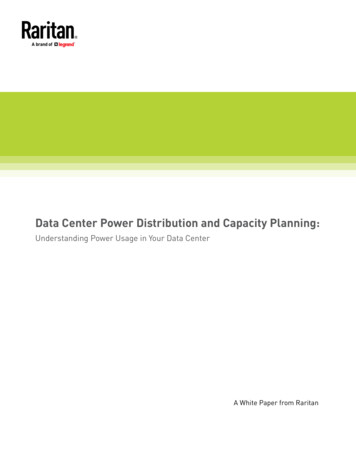
ATTACHMENT AControl of Heavy LoadsTable IILoadsReasons for not Evaluating11Spent Fuel ShippingShipping cask design for spentfuel has not been finalized andwill be evaluated at a laterdate, prior to use.13GE Mbdel 1600 CaskShipping cask design for spentfuel has not been finalized andwill be evaluated at a laterdate, prior to use.16Fuel Pool Shield BlocksDuplicate of Table I,item #3.18Drywell Radiation ShieldThis item is not handled by thereactor building crane.19RPV Head PipingDoes not have any lifting lugs.20Fuel PreparationPer GE Dwg 718E624 (BechtelV.P. 5828-APED-8A-4) Weightof the load is only 750 lbsand only handles fuel whileconnected to the pool wall.Item No.RKRA-4
ATTACHMENT BResponse to Request for Informationin Section 2.1.3. of NRC Generic Letter 81-07NBC Question 2.1.3 fVerification that crane design complies with the guidelines of CMAA Specification 70 and Chapter 2-1 of ANSI B30.2 - 1976, including the denonstrationof equivalency of actual design requirements for instances where specificcompliance with these standards is not provided.ResponseSee attached report.B-1
ATTACHMENT BREACTOR BUILDING AND TURBINE BUILDING CRANE DESIGN REVIEWCMAA Specification 70 and ANSI B30.2-1976 apply to the ReactorBuilding and Turbine Building Cranes.The Reactor Building and Turbine Building Cranes were designed tocomply with EOCI Specification 61, which was superseded by CMAA.Specification 70.The differences between these two specificationswhich impact the evaluation of the safe handling of heavy loads areaddressed below with respect to the Reactor Building and TurbineBuilding Cranes; The .evaluation will take into consideration therequirements of CMAA specification 70, ANSI B30.2-1976 and'theguidance of Regulatory Guide 1.13.It is to be noted that the Franklin Research Center, a division ofthe Franklin Institute, conducted a comparison of the 1.Generally,therequirements of CMAA-70 represent the codification of good engineering practice which should have been incorporated in cranes .builtto EOCI-61 specification although specific requirements were notcontained in EOCI-61. The Franklin Research Center study isaddressed in "Technical Evaluation Report", NRC Docket No. 50-334,dated September 24, 1981 performedh under NF C Contract No. NRC-0379-18.The following generally tracks those points of concern addressed inthe referenced Franklin Institute comparison for the NRC.Hoist Rope Safety FactorCMAA-70 requires the hoist rope safety factor to be calculated onthe combined weight of the bottom block assembly and the ratedload. This requirement is met by the Reactor Building and TurbineBuilding Cranes.Structural SteelCMAA-70 requires ASTM A36 structqral steel. The ordinary structuralsteel for Reactor Building and Turbine Building cranes conformswith ASTM A36 and low alloy structural steel conforms to ASTM A242.Stress RequirementsAlthough the specification requirements differ, the stress requirementsof CMAA-70 for bridge girders, end trucks -and trolley frames aremet by the Reactor Building and Turbine Building Cranes.B-2
IFATTACHMENT BACrane Hook LatchesANSI B30.2-1976 adds the additional requirements, applicable to safeheavy load handling, that crane hooks have latches, if practical, inthat application. This requirement is met by the Reactor BuildingandTurbine Building Cranes.Impact AllowanceCMAA-70, Article 3.3.2.1.1.3 requires that crane design calculationsinclude an impact allowance of 0.5% of the load per foot per minuteof hoisting speed but not less than 15%. EOCI-61 specifies onlya maximum allowance of 15%. Consequently, for cranes with'hoistspeeds in excess of 30 feet per minute, it is possible that theimpact allowance applied under EOCI-61 will be less than thatrequired by CMAA-70. The overhead cranes subject to this reviewoperate at hoist speeds not in excess of 30 fpm.Torsional ForcesCMAA-70, Article 3.3.2.1.3 requires that twisting moments due tooverhanging loads and lateral forces acting eccentric to thehorizontal neutral axis of a girder be calculated on the basis ofthe distance between the center ot gravity!of the load, or forcecenter line, and the girder shear center measured normal to theforce vector. EOCI-61 states that such moments are to be calculatedwith reference to girder center of gravity. For girder sectionssymmetrical about each principal central axis, e.g., box section orI-beam girders, the shear center coincides with the centroid of thegirder section and there is no difference between the two requirements.Box section girders are used for the Reactor Bui-lding and TurbineBuilding Cranes.Bending StressCMAA-70, Article 3.3.2.2 requires that bending stress calculationsinclude a wind load of 5 pounds per square foot in design stresscalculations based on the sum of dead and live loads. EOCI-61requires that the design of outdoor cranes include a wind load of10 pounds per square foot of projected area but is not specificconcerning the combination of wind loads with other dead and liveloads. Although the combination of a wind load with other designloading calculations constitutes a codification of.the same goodengineering practice that would have been used in the cranes builtto EOCI-61 specifications, the Reactor Building and Turbine Cranesare installed indoors and therefore are not subject to wind loading.B-3
ATTACHMENT BLongitudinal StiffenersCMAA-70, Article 3.3.3.1 specifies the maximum allowable web depth/thickness (h/t) ratio for box girders using longitudinal stiffenersand requirements concerning the location and minimum moment ofinertia for such stiffeners. EOCI-61 allows the use of longitudinal stiffeners but provides no similar guidance. Requirementsof CMAA-70 represent a codification of the girder design practiceand the design standards employed in the Reactor Building andTurbine Building Cranes built to EOCI-61 specifications.Allowable Compressive StrengthCMAA-70, Article 3.3.3.1.3 identifies allowable compressive stressesto be approximately 50% of yield strength of the recommendedstructural material (A-36) for girders, where the ratio of the.distance between web plates to the thickness of the top cover plate(b/c ratio) is less than or equal to 38. Allowable compressivestresses decrease linearly for b/c ratios in excess of 38.EOCI-61provides a similar method for calculating allowable compressivestresses except that the allowable stress decreases from approximately 50% of yield only after the b/c ratio exceeds 41. Consequently, structural members with b/c ratios in the general rangeof 38 to 52 designed under EOCI-61,wi 1 allow a slightly highercompressive stress than those designed under CMAA-70. This variation is not of consequence since the b/c ratios of structuralmembers for the Reactor Building and Turbine Building Cranes are13.5 and 17.5, respectively.Fatigue ConsiderationsCMAA-70, Article 3.3.3.1.3 provides substantial guidance withrespect to fatigue failure by indicating allowable stress rangesfor various structural members in joints under repeated loads.EOCI-61 does not address fatigue failure. The requirements ofCMAA-70 are not of consequence for the Reactor Building and TurbineBuilding Cranes since these cranes are not generally subjected tofrequent loads at or near designiconditions (CMAA-70 providesallowable stress ranges for loading cycles in excess of 20,000)and are not generally subjected to stress reversal (CMAA-70 allowable stress range is reduced to below the basic allowable stressfor only a limited number of -joint configurations).-,Hoist Rope RequirementsCMAA-70, Article 4.2.1 requires that the capacity load, plus thebottom block, divided by the number of parts of rope, not exceed20% of the published rope breaking strength. EOCI-61 requiresthat the rated capacity load divided by the number of parts ofrope, not exceed 20% of the published rope breaking strength. TheB-4
ATTACHMENT Bcapacity load plus the bottom block, divided by the number ofparts of rope yields 4.36 tons and 7.97 tons for the ReactorBuilding and Turbine Building Cranes, respectively. These valuesare less than 20 percent of the published breaking strengths of39.3 tons and 44.9 tons, for 7/8 inch and one inch 6 x 37 ImprovedPlow Steel Fiber Core Wire Rope, for the Reactor Building andTurbine Building Cranes, respectively.Drum Design Crushing and Bending LoadsCMAA-70, Article 4.4.1 requires that the drum be designed to withstand combined crushing and bending loads.EOCI-61 requires onlythat the drum be designed to withstand maximum load bending andcrushing loads with no stipulation that these loads be combined.This variation is not expected to be of consequence since the requirements of CMAA-70 represent the codification of good engineeringpractice which has been incorporated in the Reactor Building Cranebuilt to CMAA-70, and Turbine Building Cranes built to EOCI-61specification, although a specific requirement was not contained inEOCI-61Drum Design Groove Depth and PitchCMAA-70, Article 4.4.3 provides recommended drum groove depth andpitch. The Reactor Building Crane drum groove depth and pitch wasdesigned in accordance with CMAA-70. EOCI-61 provides no similarguidance. The recommendations in CMAA-70 constitute a codificationof good engineering practice with regard to reeving stability andreduction of rope wear and are not expected to differ substantiallyfrom practices employed in the design of the Turbine Building Cranebuilt to EOCI-61 specification.Gear DesignCMAA-70, Arti
of CMAA-70 represent a codification of the girder design practice and the design standards employed in the Reactor Building and Turbine Building Cranes built to EOCI-61 specifications. Allowable Compressive Strength CMAA-70, Article 3.3.3.1.3 identifies allowable compressive stresses to be approximately 50% of yield strength of the recommended