Transcription
Introduction to Rational Unified ProcessIntroduction to Rational Unified ProcessUnified Software Practices v 5.0-DCopyright 1998 Rational Software, all rights reservedIng. Giuseppe CalavaroCorso Informatica IndustrialeUniversità degli studi di Roma “Tor Vergata”AA 1999/20001Page 1
Introduction to Rational Unified ProcessObjectives: Rational Unified Process!!!!!!!!!Describe the six software development best practicesDescribe the Unified Modeling Language (UML)Define what a software development process isDescribe the Rational Unified ProcessExplain the four phases of the Rational Unified Process andtheir associated milestonesDefine iterations and their relation to phasesExplain the relations between phases, iterations, andworkflowsDefine artifact, worker, and activityState the importance of automated tool supportUnified Software Practices v 5.0-DCopyright 1998 Rational Software, all rights reserved2In this module, we take a high-level look at the Rational Unified Process, ourprocess for the UML that supports and encourages the best practices wediscussed earlier.Software development is the process of developing a software system fromrequirements. A software process provides a disciplined approach toassigning tasks and responsibilities within a development organization, toensure production of a high-quality software product that meets the needs ofits end users within a predictable schedule and budget. The Rational UnifiedSoftware Process is a software process which incorporates the six principlesfor software development we have just examined. It codifies them into aformal, written set of procedures and practices that are complete, thorough,and self-consistent.Ing. Giuseppe CalavaroCorso Informatica IndustrialeUniversità degli studi di Roma “Tor Vergata”AA 1999/2000Page 2
Introduction to Rational Unified ProcessSoftware Development Situation AnalysisWorld economiesincreasingly softwaredependentApplications expandingin size, complexity, &distributionBusiness demandsincreased productivity &quality in less timeNot enough qualifiedpeopleUnified Software Practices v 5.0-DCopyright 1998 Rational Software, all rights reserved3The good news for software professionals is that worldwide economies arebecoming increasingly dependent on software. The kinds of software-intensivesystems that improvements in technology make possible, and that societydemands, are expanding in size, complexity, distribution, and importance. Inthe US alone, we spend more than 250 billion each year on IT applicationdevelopment of approximately 175,000 projects (Source: Chaos Report,http://www.standishgroup.com).The bad news is that these systems are expanding in size, complexity,distribution, and importance, for it pushes the limits of what we in the softwareindustry know how to do. Poor quality software is becoming more visible. Weoften read about it in the newspaper! Some significant examples include:AT&T. A software switching system failed and hindered long distancecommunication in the US for almost 24 hours. The resolution required achange to a single line of code.Denver Airport. Software defects delayed the airport’s opening almost 9months, at an estimated taxpayer cost of about 1/2 million dollars / day.Further compounding the problem, businesses continue to demand increasedproductivity and quality with faster development and deployment. Additionally,the supply of qualified development personnel is not keeping pace with thedemand. 1998 estimates of open software jobs range from 200,000 to400,000. Economists predict that another million new programmers will beneeded within the next nine years.Ing. Giuseppe CalavaroCorso Informatica IndustrialeUniversità degli studi di Roma “Tor Vergata”AA 1999/2000Page 3
Introduction to Rational Unified ProcessSoftware Development is a Job for TeamsChallengesPerformanceEngineer Larger teamsAnalyst Specialization DistributionProjectManager Rapid ied Software Practices v 5.0-DCopyright 1998 Rational Software, all rights reserved4Because of the size and complexity of modern software systems, softwaredevelopment is a team endeavor. Larger teams present communicationchallenges which are aggravated if the team is distributed. Complextechnologies require experts who specialize in only one area. A team mayinclude many such specialists. It is a challenge to ensure they communicateeffectively with the rest of the team and that all technologies are integrated toproduce a successful system. The pace of technological change continues toaccelerate and many technologies are used before they have been proven.Ing. Giuseppe CalavaroCorso Informatica IndustrialeUniversità degli studi di Roma “Tor Vergata”AA 1999/2000Page 4
Introduction to Rational Unified ProcessSymptoms of Software Development ProblemsInaccurate understanding of end-user needsInability to deal with changing requirementsModules that don’t fit togetherSoftware that’s hard to maintain or extendLate discovery of serious project flawsPoor software qualityUnacceptable software performanceTeam members in each other’s way, unable to reconstructwho changed what, when, where, why! An untrustworthy build-and-release process!!!!!!!!Unified Software Practices v 5.0-DCopyright 1998 Rational Software, all rights reserved5Producing quality software on time is very challenging; a large numberobstacles and problems must be overcome. Problems are often firstrecognized by their symptoms. These are some all-too-common ones.The reality is that we can’t stop change. We used to try to baselinerequirements at the start of a project and then resist all changes to them. Abetter approach is to develop practices that allow us to manage change whenit occurs, with minimal impact to the development process.An example associated with software that’s hard to maintain or extend is theYear 2000 (Y2K) problem. The software itself has been unexpectedlysuccessful, lasting well beyond its estimated end of life projections. But thesoftware is very hard to modify since the Y2K problem is pervasive. It occursthroughout the software and each occurrence must be found and fixedindividually.Ing. Giuseppe CalavaroCorso Informatica IndustrialeUniversità degli studi di Roma “Tor Vergata”AA 1999/2000Page 5
Introduction to Rational Unified ProcessTreating Symptoms Does Not Solve the ProblemRoot CausesSymptomsinsufficient requirementsend-user ittle architecturesmodules don’t fitoverwhelmingcomplexityhard to maintainlate discoveryundetectedinconsistenciespoor qualitypoor opmentuncontrolled changeinsufficient automationUnified Software Practices v 5.0-DCopyright 1998 Rational Software, all rights reserved6Unfortunately, treating these symptoms does not treat the disease. Forexample, late discovery of serious project flaws is only a symptom of largerproblems, namely, inadequate testing. Waterfall development compounds theproblem since testing is done very late in the development schedule when theflaws discovered cannot be corrected without a significant delay in delivery.From Rational's many collective years working with customers, we haveidentified a set of root causes that underlie these symptoms.Ing. Giuseppe CalavaroCorso Informatica IndustrialeUniversità degli studi di Roma “Tor Vergata”AA 1999/2000Page 6
Introduction to Rational Unified ProcessRoot Causes of Software Development Problems!!!!!!!!!!Insufficient requirements managementAmbiguous and imprecise communicationsBrittle architecturesOverwhelming complexityUndetected inconsistencies among requirements, designs,and implementationsInsufficient testingSubjective project status assessmentDelayed risk reduction due to waterfall developmentUncontrolled change propagationInsufficient automationUnified Software Practices v 5.0-DCopyright 1998 Rational Software, all rights reserved7These root causes have been determined by analyzing Rational’s experiencein developing its software products together with the experience of Rational’smany customers. Common patterns and themes have been detected and aredocumented as these root causes and the best practices that address them.Insufficient requirements management makes scope creep inevitable andseriously jeopardizes the development team’s ability to bring the project to aconclusion on time.Brittle architectures are architectures that break easily in response to stress orrequirements/technology changes. They typically provide no reusablecomponents nor are they based on a reusable framework.Subjective project status assessment depends on subjective estimates of thelevel of “doneness”. This is often referred to as the “90% done, 90%remaining” phenomenon. In other words, the developers estimate that they are90% done, but it takes 90% of project resources to get the rest of the way to100% done.Ing. Giuseppe CalavaroCorso Informatica IndustrialeUniversità degli studi di Roma “Tor Vergata”AA 1999/2000Page 7
Introduction to Rational Unified ProcessBest Practices Address Root CausesRoot Causes""""""""""Best PracticesInsufficient requirementsAmbiguous communicationsBrittle architecturesOverwhelming complexitySubjective assessmentUndetected inconsistenciesPoor testingWaterfall developmentUncontrolled changeInsufficient automationUnified Software Practices v 5.0-DCopyright 1998 Rational Software, all rights reserved""""""Develop iterativelyManage requirementsUse component architecturesModel the software visuallyVerify qualityControl changes8Treat these root causes and you’ll eliminate the symptoms. Eliminate thesymptoms, and you’ll be in a much better position to develop quality softwarein a repeatable and predictable fashion.Best practices are a set of commercially proven approaches to softwaredevelopment which, when used in combination, strike at the root causes ofsoftware development problems. These are so called “best practices” not sosuch much because we can precisely quantify their value, but rather, becausethey are observed to be commonly used in industry by successfulorganizations.These six best practices form the foundation of the Rational Unified Process.They are documented in The Rational Unified Process - An Introduction, byPhilippe Kruchten (Addison-Wesley-Longman, 1998).Ing. Giuseppe CalavaroCorso Informatica IndustrialeUniversità degli studi di Roma “Tor Vergata”AA 1999/2000Page 8
Introduction to Rational Unified ProcessAddressing Root Causes Eliminates the SymptomsSymptomsRoot CausesBest Practicesend-user needsinsufficient requirementsdevelop ionsmanage requirementsmodules don’t fitbrittle architectureshard to maintainoverwhelming complexitylate discoveryundetectedinconsistenciespoor qualitypoor performancecolliding developersbuild-and-releasepoor testinguse componentarchitecturesmodel the softwarevisuallyverify qualitycontrol changessubjective assessmentwaterfall developmentuncontrolled changeinsufficient automationUnified Software Practices v 5.0-DCopyright 1998 Rational Software, all rights reservedIng. Giuseppe CalavaroCorso Informatica IndustrialeUniversità degli studi di Roma “Tor Vergata”AA 1999/20009Page 9
Introduction to Rational Unified ProcessBest Practices of Software EngineeringDevelop IterativelyUseManageComponentRequirements ArchitecturesModelVisuallyVerifyQualityControl ChangesUnified Software Practices v 5.0-DCopyright 1998 Rational Software, all rights reserved10In the remainder of this module, we describe recommended softwaredevelopment practices and give the reasons for these recommendations. Wewill use this key graphic again and again in presenting the 6 best practices.Ing. Giuseppe CalavaroCorso Informatica IndustrialeUniversità degli studi di Roma “Tor Vergata”AA 1999/2000Page 10
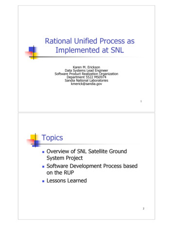
Introduction to Rational Unified ProcessIn Building a System, a Language Is Not EnoughTeam-BasedDevelopmentModelingLanguageUnified Software Practices v 5.0-DCopyright 1998 Rational Software, all rights reservedUnifiedProcess11The UML provides a standard for the artifacts of development (semanticmodels, syntactic notation, and diagrams): the things that must be controlledand exchanged. But the UML is not a standard for the process ofdevelopment.Despite all of the value that a common modeling language brings, successfuldevelopment of today’s complex systems cannot be achieved solely by theuse of the UML. Successful development also requires the employment of anequally robust development process.Ing. Giuseppe CalavaroCorso Informatica IndustrialeUniversità degli studi di Roma “Tor Vergata”AA 1999/2000Page 11
Introduction to Rational Unified ProcessWhat Is the UML?! The Unified Modeling Language (UML) is a language for SpecifyingVisualizingConstructingDocumentingthe artifacts of a software-intensive systemUnified Software Practices v 5.0-DCopyright 1998 Rational Software, all rights reserved12The software systems we develop today are much more complex than thehuman mind can comprehend in their entirety. This is why we model systems.The choice of what models to create has a profound influence upon how aproblem is attacked and how a solution is shaped. No single model issufficient; every complex system is best approached through a small set ofnearly independent models. To increase comprehension, a common languagelike the Unified Modeling Language is used to express models.Ing. Giuseppe CalavaroCorso Informatica IndustrialeUniversità degli studi di Roma “Tor Vergata”AA 1999/2000Page 12
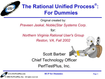
Introduction to Rational Unified ProcessUML HistoryUnified Software Practices v 5.0-DCopyright 1998 Rational Software, all rights reserved13The UML is now the industry standard modeling language. Its developmentwas spearheaded by three leaders in the object-oriented industry: GradyBooch, Ivar Jacobson, and Jim Rumbaugh. Each of them had uniqueapproaches in the early 1990s that were converging independently. RationalSoftware brought these three industry leaders together to accelerateconvergence to a single modeling approach. The UML is the outcome of thateffort.The UML has been under development since 1990. Early versions havegradually converged into the UML standard 1.1 that was adopted unanimouslyby the OMG in November 1997. Numerous books, articles, and papers havebeen written about or are using the UML today and many more are to come.And finally, most tool vendors today are supporting the UML.Version 1.3 of the UML is under development at the present time.Ing. Giuseppe CalavaroCorso Informatica IndustrialeUniversità degli studi di Roma “Tor Vergata”AA 1999/2000Page 13
Introduction to Rational Unified ProcessInputs to UMLBoochRumbaughJacobsonMeyerOperation descriptions,Message numberingBefore and afterconditionsEmbleyHarelSingleton classes,High-level viewState chartsGamma, et.alWirfs-BrockFrameworks, patterns,notesShlaer - MellorObject LifecyclesUnified Software Practices v 5.0-DCopyright 1998 Rational Software, all rights 4UML development included incorporating ideas from numerous othermethodologists. The main challenge was constructing an approach that wassimple yet allowed the modeling of a broad range of systems. The conceptualframework was established quickly but the notational semantics took moretime.Active collaboration with other industry leaders has brought unique expertiseand experience into the UML effort. The UML effort was supported by a largecross-section of the industry. Partners in the UML effort included HP, ICONComputing, IBM, I-Logix, Intellicorp, MCI Systemhouse, Microsoft, ObjecTime,Oracle, Platinum Technology, Ptech, Reich Technologies, Softeam, SterlingSoftware, Taskon, and Unisys. These partners provided contributors,reviewers, and advocates for the standardization efforts.In the end, a modeling language was created that has already stood up to thetest of widespread use in the industry and to the scrutiny of internationalstandardization efforts.Ing. Giuseppe CalavaroCorso Informatica IndustrialeUniversità degli studi di Roma “Tor Vergata”AA 1999/2000Page 14
Introduction to Rational Unified ProcessThe UML Provides Standardized msUnified Software Practices v 5.0-DCopyright 1998 Rational Software, all rights gramsComponentDiagramsDiagramsDiagrams15In building a visual model of a system, many different diagrams are needed torepresent different views of the system. The UML provides a rich notation forvisualizing our models. This includes the following key diagrams: Use-Case diagrams to illustrate user interactions with the system. Class diagrams to illustrate logical structure. Object diagrams to illustrate objects and links. State diagrams to illustrate behavior. Component diagrams to illustrate physical structure of the software. Deployment diagrams to show the mapping of software to hardwareconfigurations. Interaction diagrams (i.e., collaboration and sequence diagrams) toillustrate behavior. Activity diagrams to illustrate the flow of events in a Use-Case.Ing. Giuseppe CalavaroCorso Informatica IndustrialeUniversità degli studi di Roma “Tor Vergata”AA 1999/2000Page 15
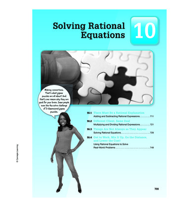
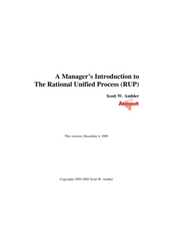
Introduction to Rational Unified ProcessA Sample UML Diagram: Use-CasesA University Course Registration SystemRegister for CoursesStudentSelect Courses to TeachCourse CatalogProfessorMaintain Professor InformationRegistrarMaintain Student InformationClose RegistrationBilling SystemUnified Software Practices v 5.0-DCopyright 1998 Rational Software, all rights reserved16Use-Case diagrams are used to show the existence of Use-Cases and theirrelationships, both to each other and to actors. An actor is something externalto the system that has an interface with the system, such as users. A UseCase models a dialogue between actors and the system. A Use-Case isinitiated by an actor to invoke a certain functionality in the system. Forexample, in the diagram above, one user of the system is a student whowishes to use the system to register for courses. Hence, Register for Coursesis a Use-Case.The arrow (which is optional) indicates the direction of initiation of theinteraction. For example, the Student actor initiates the Register for CoursesUse-Case. However, the Close Registration Use-Case initiates interactionwith the Billing System.A Use-Case is a complete and meaningful flow of events. The flow of eventssupplements the Use-Case diagram and is usually provided in text format.Taken together, all Use-Cases constitute all possible ways of using thesystem.Ing. Giuseppe CalavaroCorso Informatica IndustrialeUniversità degli studi di Roma “Tor Vergata”AA 1999/2000Page 16
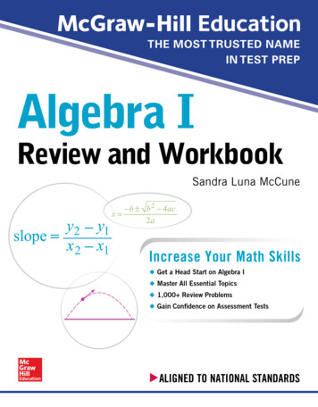
Introduction to Rational Unified ProcessA Sample UML Diagram: ClassesA University Course Registration System boundary MaintainScheduleForm boundary MainForm// select maintain schedule()10.1 // open() // select 4 primary and 2 alternate offerings()11 boundary CourseCatalogSystem10.* control RegistrationController// add courses to schedule()// get course offerings ()// get course offerings()0.11 entity ScheduleUnified Software Practices v 5.0-DCopyright 1998 Rational Software, all rights reserved// create with offerings()17A class diagram is a view of the classes composing the system, as well astheir relationships. Classes are represented by rectangles. Relationships arerepresented by lines. The presence of a relationship between two classesindicates that they collaborate in some way in performing one or more UseCases. For example, the relationship between MainForm andMaintainScheduleForm means that a MainForm may or may not contain oneMaintainScheduleForm.The items preceded by “//” in the lower third of the class boxes indicate theresponsibilities of the classes. For example, CourseCatalogSystem isresponsible for get course offerings. During design of this class, thisresponsibility will be turned into one or more operations.The items within angle brackets (“ ”) indicate the stereotype of the class.For example, CourseCatalogSystem is a boundary class which means that itinterfaces with an external entity (I.e., an actor).Ing. Giuseppe CalavaroCorso Informatica IndustrialeUniversità degli studi di Roma “Tor Vergata”AA 1999/2000Page 17
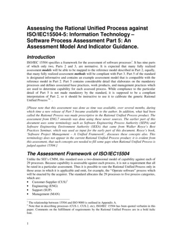
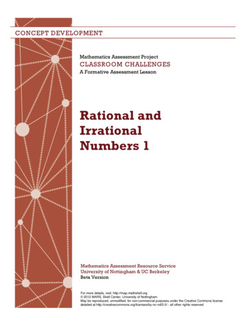
Introduction to Rational Unified ProcessUML Diagrams Are Key ArtifactsUse-CaseDiagramClass DiagramState DiagramDocumentadd( )delete( )name : intdocid : intnumField : intget( )open( )close( )read( )sortFileList( )create( )fillDocument( )FileListUse-Case 1fListadd( )delete( )Actor AWritingadd file [ numberOffile MAX ] /flag OFFread() fill thecode.Openningclose file1Actor Bclose fileReadingClosingrepUse-Case 2FileRepository(from Persistence)read( ) entity pFilename : char * 0DomainExpertadd fileDocumentListFileMgrfetchDoc( )sortByName( )read( )open( )create( )fillFile( )readDoc( )readFile( )Use-Case 3DeploymentDiagramUIClassMFCDocumentAppºÐ»ê È æÀÇ Çϵå¿þ¾î¹ ³ Æ ¿ À ·ÎÀÇ Á º ½Ã½ºÅÛ ¿ á ðµ - À µµ¿ì 95 : Å ¶óÀ̾ðÆ - À µµ¿ì NT: ÀÀ¿ë¼-¹ö- À нº Ó½Å: ÀÀ¿ë ¼-¹ö ¹ µ ÀÌÅ ¼-¹ö, Åë½Å ¼-¹ö- IBM ÞÀÎÇÁ·¹ÀÓ: µ ÀÌÅ ¼-¹ö, Åë½Å ¼-¹öRogueWaveRepositoryPersistence9: sortByName ( )DocumentListWindows95Window95Windows95global¹ ¼- ü Å ¶óÀ̾ðÆ .EXEFileManager¹ ¼- ü ¾ÖÇà mainWnd : MainWnd1: Doc view request ( )WindowsNTL2: fetchDoc( )gFile : GrpFile4: create ( )8: fillFile ( )user : »ç¿ëÀÚUser InterfaceDefinitionfileMgr : FileMgr3: create ( )PackageDiagramDocumentSolaris¹ ¼- ü ¿ icFileFileIBMMainframeFileList6: fillDocument ( )µ ÀÌÅ º À̽º¼-¹ö7: readFile ( )5: readDoc ( )document : Documentrepository : RepositoryCollaboration DiagrammainWnduserÆ Á ¹ ¼-¿¡ ëÇÑ º â »ç¿ëÀÚ ¡ ¿äûÇÑ Ù.fileMgr :FileMgrdocument :DocumentgFileComponentDiagramForward Engineering(Code Generation)andReverse Engineeringrepository1: Doc view request ( )Source Code edit, compile, debug, link2: fetchDoc( )3: create ( )4: create ( )5: readDoc ( )È-ÀÏ ü ÀÚ Â Àоî¿Â¹ ¼-ÀÇ Á º ÇØ ç ¹ ¼ ü¿¡ ¼³Á À» ¿äûÇÑ Ù.6: fillDocument ( )7: readFile ( )8: fillFile ( )È- é ü  ÀоîµéÀΠüµé¿¡ ëÇØ ÀÌ §º ·ÎÁ ·ÄÀ» ½ÃÄÑ È- é¿¡º ¿ ÁØ Ù.9: sortByName ( )Sequence DiagramExecutable SystemUnified Software Practices v 5.0-DCopyright 1998 Rational Software, all rights reserved18The UML provides a single, common modeling language that is useableacross many methods, across the entire lifecycle, and across many differentimplementation technologies. It maps the artifacts between businessengineering, requirements capture and analysis, design, implementation, andtest. It defines an expressive and consistent notation that can point outomissions and inconsistencies. It scales to support very small to very largesystems development. If facilitates effective communications with all membersof the development team.Ing. Giuseppe CalavaroCorso Informatica IndustrialeUniversità degli studi di Roma “Tor Vergata”AA 1999/2000Page 18
Introduction to Rational Unified ProcessWhat Is a Process?A process defines Who is doing What, When and How toreach a certain goal. In software engineering the goal is tobuild a software product or to enhance an existing oneNew or changedrequirementsUnified Software Practices v 5.0-DCopyright 1998 Rational Software, all rights reservedSoftware EngineeringProcessNew or changedsystem19The UML is a generic modeling language. With UML, you can produceblueprints for any kind of software system.The Rational Unified Process (RUP) is a generic process that uses UML as amodeling language. RUP can be used for any kind of software system.Ing. Giuseppe CalavaroCorso Informatica IndustrialeUniversità degli studi di Roma “Tor Vergata”AA 1999/2000Page 19
Introduction to Rational Unified ProcessAn Effective Process .! Provides guidelines for efficient development of qualitysoftware! Reduces risk and increases predictability! Captures and presents best practices# Learn from other’s experiences# Mentor on your desktop# Extension of training material!!!Promotes common vision and cultureProvides roadmap for applying toolsDelivers information on-line, at your finger tipsUnified Software Practices v 5.0-DCopyright 1998 Rational Software, all rights reserved20The focus of the process is the production of high-quality executables with aminimum of overhead, rather than what documents to produce.By providing a “written-down”, very detailed set of procedures for developingsoftware according to Rational’s six best practices, the process is easier toapply and repeatable. This results in software projects that are morepredicable and successful.Another feature of the Rational Unified Process is that it is not just theory. Itinstructs the developer on how to implement the activities using the tools thedeveloper is using.Finally, the process is available on-line as a Website. While hardcopy bookshave their place, most developers prefer to reference the process from theirdesktops when they need help. Both hardcopy and on-line versions areavailable.Ing. Giuseppe CalavaroCorso Informatica IndustrialeUniversità degli studi di Roma “Tor Vergata”AA 1999/2000Page 20
Introduction to Rational Unified ProcessRational Unified Process Delivers Best PracticesRational Unified Process describes how to effectivelyimplement the six best practices for software developmentDevelop IterativelyUseManageComponentRequirements ArchitecturesModelVisuallyVerifyQualityControl ChangesUnified Software Practices v 5.0-DCopyright 1998 Rational Software, all rights reserved21The six best practices examined in the previous module provide the basis forthe Rational Unified Process. However, their effective application requiresstep-by-step instructions. These instructions are provided in the RationalUnified Process, which looks at all activities that must be performed to build asoftware product and describes how to conduct those activities consistent withthe 6 best practices. Tool mentors are included to explain how to conductthose activities using the Rational tool set.Ing. Giuseppe CalavaroCorso Informatica IndustrialeUniversità degli studi di Roma “Tor Vergata”AA 1999/2000Page 21
Introduction to Rational Unified ProcessRational Unified Process Is Use-Case DrivenAn actor is someone orsomething outside thesystem that interactswith the systemA Use-Case is a sequenceof actions a systemperforms that yields anobservable result ofvalue to a particularactorCheck BalanceCustomerWithdraw MoneyUse-Cases for a Cash MachineUnified Software Practices v 5.0-DCopyright 1998 Rational Software, all rights reserved22Managing requirements is one of the six best practices already discussed. Inparticular, the Rational Unified Process captures and manages functionalrequirements in a Use-Case model. Use-Cases are a key concept within theprocess. They are used throughout the development cycle as a driver formany activities, flowing information through several models, and encouragingconsistency across these models.An actor can be a human being or another system or a device; anythingexternal with which the system interacts.A Use-Case describes functionality from the user’s point of view. A bankcustomer can use a cash machine to withdraw money or check the balance ofher account. Each Use-Case (oval) represents something that the systemdoes to provide value to the bank’s customer, the Customer. The collectedUse-Cases constitute the use-case model and represent all the possible waysof using the system. The use-case model is a model of the system’s intendedfunctions and its environment, and it serves as a contract between thecustomer and the developers.The use-case model is complemented by non-functional specificationscovering some of the aspects that cannot be easily conveyed by a Use-Case,or that apply to many or all Use-Cases; for example, high-level productrequirements, development constraints, safety or security attributes, and soon.The notation used for representing the use-case model in diagrams isstandard notation provided by the UML.Ing. Giuseppe CalavaroCorso Informatica IndustrialeUniversità degli studi di Roma “Tor Vergata”AA 1999/2000Page 22
Introduction to Rational Unified ProcessUse-Cases Include a Flow of EventsFlow of events for the Withdraw Money Use-Case1. The Use-Case begins when the customer inserts a cash card.The system reads and validates information on the card.2. The system prompts for the PIN. The system validates thePIN.3. The system asks which operation the customer wishes toperform. The customer selects “Cash withdrawal.”4. The system requests the amount. The customer enters theamount.5. The system requests the account type. The customer selectschecking or savings.6. The system communicates with the ATM network . . .Unified Software Practices v 5.0-DCopyright 1998 Rational Software, all rights reserved23The most important part of the Use-Case is the its flow of events, describingthe sequence of actions. It is written in natural language, in a simple,consistent prose, with a precise use of terms, drawing upon a commonglossary of the problem domain. For example, the term “ATM” would be anacronym
Objectives: Rational Unified Process! Describe the six software development best practices! Describe the Unified Modeling Language (UML)! Define what a software development process is! Describe the Rational Unified Process! Explain the four phases of the Rational Unified Process and their associated milestones! Define iterations and their .