Transcription
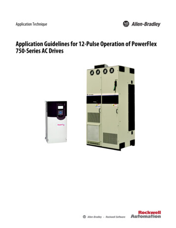
MAXREFDES117#: HEART-RATE AND PULSE-OXIMETRYMONITORThe MAXREFDES117# reference design is a low power, optical heart-rate module completewith integrated red and IR LEDs, and a power supply. This tiny board, perfect for wearableprojects, may be placed on a finger or earlobe to accurately detect heart rate. This versatilemodule works with both Arduino and mbed platforms for quick testing, development andsystem integration. A basic, open-source heart-rate and SpO2 algorithm is included in theexample firmware.The board features 8 sewing tap pads for attachment and quick electrical connection to adevelopment platform.As with all Maxim reference designs, the BOM, schematics, layout files, and Gerber files areall available from the Design Resources tab. In addition, boards are available for purchase.Features Optical Heart-Rate Monitor and Pulse Oximetry SolutionTiny 12.7mm x 12.7mm (0.5in x 0.5in) Board SizeLow PowerDevice DriversFree AlgorithmExample C Source Code For Arduino And mbed PlatformsTest DataCompetitive Advantages Highly-integrated, small-size sensorNon-chest based heart-rate/SpO2 detectionUltra-low power consumptionApplications WearablesHeart-rate monitorPulse oximeter
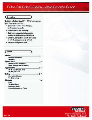
MAXREFDES117# System BoardIntroductionWearable devices hold the potential to transform health and medical monitoring. Heart rate,specifically, provides tremendous insight into heart function and health, during both activityand rest. Innovation and development of both optical semiconductors and lower-powerintegrated circuits makes the transition to wearables possible. Until now, only largeorganizations, with deep development budgets, could deliver such advanced products.MAXREFDES117# delivers the promise of wearable devices to all developers. This uniquedesign measures both heart rate and pulse oximetry. MAXREFDES117# features theMAX30102 with integrated red and IR LEDs for heart-rate and SpO2 detection. Thisconfiguration ideally detects heart rate and pulse ox on a person’s fingertip, earlobe, or otherfleshy extremity. The small board size of 12.7mm x 12.7mm (0.5in x 0.5in) is ideal forwearable applications and may be stitched into fabric for immediate prototyping. Firmware isavailable for both Arduino and mbed platforms, enabling users to develop with virtually anyplatform. User needs to provide a 2V to 5.5V supply at the power input, perfect for virtuallyany battery or Arduino and mbed form-factor board.The MAXREFDES117# design utilizes the heart-rate/SpO2 sensor (MAX30102), an efficient,low-power step-down converter (MAX1921), and an accurate level translator (MAX14595).The entire design typically operates at less than 5.5mW when using with the examplefirmware. A block diagram of the system is shown in Figure 1.
System DiagramFigure 1. MAXREFDES98# reference design block diagram.The power requirement is shown in Table 1.Table 1. Power Requirement for the MAXREFDES117# ReferenceDesignInput Voltage (V)Input Current(mA, typ)2V to 5.5V1.5mA (3.3V input)Note: Controller board is powered separatelyThe MAXREFDES117# reference design is a PPG-based heart-rate and SpO2 monitorsubsystem. The circuit utilizes the MAX30102 heart-rate/SpO2 sensor with integrated redand IR LEDs. The step-down converter MAX1921 converts the 2V to 5.5V supply input andgenerates the 1.8V rail for the heart-rate sensor. The MAX14595 level translator provides aninterface between the heart-rate/SpO2 sensor and the controller board, which generally usea different logic level.
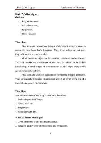
Detailed Description of FirmwareThe MAXREFDES117# can be used with virtually any microcontroller that has I2C interface.The Arduino and mbed example firmware have been tested on the following developmentplatforms:mbed: Maxim Integrated MAX32600MBED# Freescale FRDM-K64F Freescale FRDM-KL25ZArduino: Adafruit Flora Lilypad USB Arduino UNOUsers may read sampled data, calculated heart rate and SpO2 through a terminal program,allowing analysis on excel or any third-party software. The simple process flow is shownin Figure 2.Figure 2. The MAXREFDES117# firmware flowchart.
The complete source code, including the heart rateheart-rate/SpO2algorithm, is provided toaccelerate development. Code documentation can be found in the corresponding firmwareplatform files.Heart rateHeart-rate accuracy varies depending on the chosen platform. The tested mbedplatforms give more accurate heart-rate/SpO2 calculations than the tested Arduino platformsbecause the mbed platform controllers have more SRAM than the Arduino platformcontrollers. For the example firmware, mbed platforms store 5 seconds of samples collectedat 100sps, while the Arduino platforms store 4 seconds of samples collected at 25sps.SpO2 calculation is based on the equation shown below. However, determining theconstants (C1, C2, and C3) requires a comprehensive clinical study of pulse pulse-oximetrydata from a statistically significant population set using this hardware. Such a clinical study isbeyond scope of this design. Therefore, the calculated SpO2 value may havecan have anerror.SpO2 C1 AverageRatio2 C2 AverageRation C3Where AverageRatio is the average ratio of IR and red LED readings. C1, C2, and C3 areconstants.Quick StartRequired equipment: Windows PC with a USB port MAXREFDES117# board 5 cables that can be used to connect the MAXREFDES117# with the controller board One of the supported mbed or Arduino controller boards listed above One USB cable that is compatible with the selected controller boardDownload, read, and carefully follow each step in the appropriate MAXREFES117# quickStart Guide:MAXREFDES117# mbed Quick Start GuideMAXREFDES117# Arduino Quick Start Guide
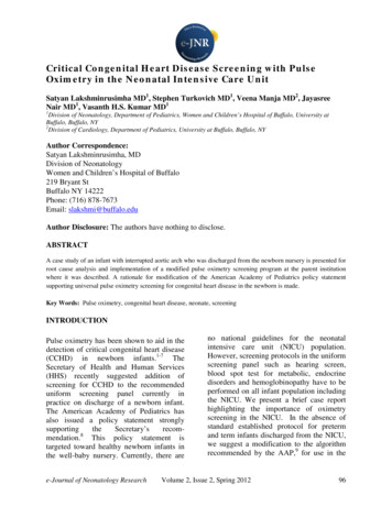
Lab MeasurementsEquipment used: MAX32600MBED# Adafruit Flora Adafruit BlueFruit Polar H7 Bluetooth Smart Heart RateHeart-Rate Sensor Android tabletFigure 3 and Figure 4 show how the MAXREFDES117 calculated heart rate compared tothe Polar H7 chest strap. The data in Figure 3 were taken while the person was sitting stillfor 20 minutes. And the data in Figure 4 were taken while the person was walking at anormal speed for 20 minutes.Figure 3. For sedentary test, over 99% of the mbed MAXREFDES117# heart heart-ratedata are less than 5 beats/min delta from the Polar H7 chest strap.
Figure 4. For moving test, over 92% of the Arduino MAXREFDES117# heart- rate data areless than 10 beats/min delta from the Polar H7 chest strap.Quick StartRequired equipment: Windows PC with a USB port MAXREFDES117# board 5 cables that can be used to connect the MAXREFDES117# with the controller board One of the supported mbed or Arduino controller boards listed above One USB cable that is compatible with the selected controller boardDownload, read, and carefully follow each step in the appropriate MAXREFDES117# quickStart Guide:MAXREFDES117# mbed Quick Start GuideQuick Start: Required equipment: Windows PC with a USB port MAXREFDES117# board 5 pieces of wires to connect the MAXREFDES117# to the controller board One of the three supported controller boards (Maxim Integrated MAX32600MBED#,Freescale FRDM-KL25Z, or Freescale FRDM-K64F) One micro USB cable (for MAX32600MBED# and FRDM-K64F) One mini USB cable (for FRDM-KL25Z) Procedure
The reference design is fully assembled and tested. Follow the steps below to verify boardoperation:1. Create an account on http://developer.mbed.org to use their online compiler.2. Import the demo program from ode/RD117 MBED/3. Connect the MAXREFDES117 to the controller board: For MAX32600MBED#MAX32600MBED# portMAXREFDES117 portP26 SDLSDAP27 SCLSCLP20 SCK RXINT3.3VVINGNDGND4. For FRDM-K64FFRDM-K64F portMAXREFDES117 portE25SDAE24SCLD1INTP3V3VINGNDGND
5. For FRDM-KL25ZFRDM-KL25Z portMAXREFDES117 portE0SDAE1SCLD1INT3.3VVINGNDGND6. Connect the controller board to the PC with a USB cable.7. In the MBED compiler, click the button at the upper right hand corner to select theappropriate controller board.8. Compile and download the resulting binary to your mbed platform.9. Press the Upload menu item in the Sketch menu to upload the firmware to the Floraboard.10. Open Hyperterminal or a similar terminal program on the PC. Find the appropriateCOM port and configure the connection for 115200, 8-N-1 with no flow control.11. Put a finger on top of the U1 on the MAXREFDES117#, contact with an earlobe isalso sufficient. Constant pressure yields the best result.12. Press any key on the terminal program and the system will start the conversion.13. From left to right, the first two column shows the data for red and IR LED receiver.Third and fifth columns show the calculated heart rate and SpO2 values. And thefourth and sixth columns show the validities of the heart rate and SpO2 calculations.MAXREFDES117# Arduino Quick Start Guide
Quick StartRequired equipment: Windows PC with a USB port MAXREFDES117# board 5 cables with grabber clips on both ends. One of the three supported controller boards (Adafruit Flora, Lilypad USB, or ArduinoUNO board) One micro USB cable (for Lilipad or Flora) One A to B USB cable (for Arduino UNO) ProcedureThe reference design is fully assembled and tested. Follow the steps below to verify boardoperation:1. If Arduino IDE is not installed on the PC follow the getting started guide to install theArduino IDE on the PC.2. If Adafruit Flora board is selected as the controller board:oFollow the Adafruit Windows Driver installation guide to install the driver.oFollow the "Adafruit Arduino IDE setup guide" to install the Arduino IDE andsupport files for Adafruit Flora board.3. Download the source code RD117 ARDUINO.zip file and unzip it in a desiredlocation.4. Double click the RD117 ARDUINO.ino to open the project in Arduino IDE.5. Connect the MAXREFDES117 to the controller board: For FloraFlora portMAXREFDES117 portSDASDASCLSCLD10INT3.3VVINGNDGND
6. For Lilypad USBLilypad USB portMAXREFDES117 port2SDA3SCL10INT VIN-GND7. For Arduino UNOArduino UNO portMAXREFDES117 portSDASDASCLSCL10INT3.3VVINGNDGND8. Connect the controller board to the PC with a USB cable.9. In the Arduino IDE, click on the Tools menu and make sure the appropriate board isselected.10. Select the proper communication port in the Tools menu.11. Press the Upload menu item in the Sketch menu to upload the firmware to the Floraboard.
12. Open Hyperterminal or a similar terminal program on the PC. Find the appropriateCOM port and configure the connection for 115200, 8-N-1 with no flow control.13. Put a finger on top of the U1 on the MAXREFDES117#, contact with an earlobe isalso sufficient. Constant pressure yields the best result.14. Press any key on the terminal program and the system will start the conversion.15. From left to right, the first two column shows the data for red and IR LED receiver.Third and fifth columns show the calculated heart rate and SpO2 values. And thefourth and sixth columns show the validities of the heart rate and SpO2 calculations.All Design FilesDownload All Design FilesHardware Files:SchematicBill of Materials (BOM)PCB LayoutPCB Fab PackagePCB CAD (PADS 9.0)Firmware Files:Arduino Platformmbed Platform
o Follow the "Adafruit Arduino IDE setup guide" to install the Arduino IDE and support files for Adafruit Flora board. 3. Download the source code RD117_ARDUINO.zip file and unzip it in a desired location. 4. Double click the RD117_ARDUINO.ino to open the project in Arduino IDE. 5. Connect the MAXREFDES117 to the controller board: For Flora