Transcription
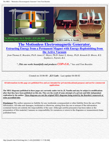
A Practical Guide to Free-Energy DevicesAuthor: Patrick J. KellyChapter 3: Motionless Pulsed SystemsNote: If you are not at all familiar with basic electronics, you might find it easier to understand this chapter if youread chapter 12 first.The pulsed devices mentioned so far have had moving parts but rotating or fluctuating magnetic fields can becreated without moving parts. An example of this is Graham Gunderson’s solid-state electric generator shown inUS Patent Application 2006/0163971 A1 of 27th July 2006 which is shown on page A-1038 of the appendix.Another example is:Charles Flynn’s Magnetic Frame.Another device of this type comes from Charles Flynn. The technique of applying magnetic variations to themagnetic flux produced by a permanent magnet is covered in detail in the patents of Charles Flynn which areincluded in the Appendix. In his patent he shows techniques for producing linear motion, reciprocal motion,circular motion and power conversion, and he gives a considerable amount of description and explanation oneach, his main patent containing a hundred illustrations. Taking one application at random:He states that a substantial enhancement of magnetic flux can be obtained from the use of an arrangement likethis:Here, a laminated soft iron frame has a powerful permanent magnet positioned in it’s centre and six coils arewound in the positions shown. The magnetic flux from the permanent magnet flows around both sides of theframe.The full patent details of this system from Charles Flynn are in the Appendix.3-1
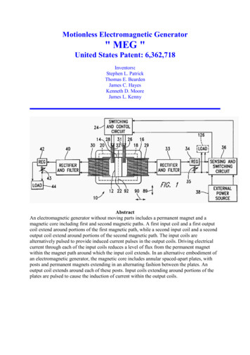
Lawrence Tseung’s Magnetic Frame.Lawrence Tseung has recently produced a subtle design using very similar principles. He takes a magnetic frameof similar style and inserts a permanent magnet in one of the arms of the frame. He then applies sharp DC pulsesto a coils wound on one side of the frame and draws off energy from a coil wound on the other side of the frame.He shows three separate operating modes for the devices as follows:Lawrence comments on three possible arrangements. The first on shown above is the standard commercialtransformer arrangement where there is a frame made from insulated iron shims in order to cut down the "eddy"currents which otherwise would circulate around inside the frame at right angles to the useful magnetic pulsingwhich links the two coils on the opposite sides of the frame. As is very widely known, this type of arrangementnever has an output power greater than the input power.However, that arrangement can be varied in several different ways. Lawrence has chosen to remove a section ofthe frame and replace it with a permanent magnet as shown in the diagram below. This alters the situation veryconsiderably as the permanent magnet causes a continuous circulation of magnetic flux around the frame beforeany alternating voltage is applied to the input coil. If the pulsing input power is applied in the wrong direction asshown here, where the input pulses generate magnetic flux which opposes the magnetic flux already flowing inthe frame from the permanent magnet, then the output is actually lower than it would have been without thepermanent magnet.However, if the input coil is pulsed so that the current flowing in the coil produces a magnetic field whichreinforces the magnetic field of the permanent magnet then it is possible for the output power to exceed the inputpower. The "Coefficient of Performance" or "COP" of the device is the amount of output power divided by theamount of input power which the user has to put in to make the device operate. In this instance the COP valuecan be greater than one:As it upsets some purists, perhaps it should be mentioned that while a square waveinput signal is applied to the input of each of the above illustrations, the output willnot be a square wave although it is shown that way for clarity. Instead, the inputand output coils convert the square wave to a low-quality sine wave which onlybecomes a pure sine wave when the pulse frequency exactly matches the resonantfrequency of the output winding. The oscilloscope display shown here is a typicaloutput power waveform which has nearly 390,000 of these pulses per second.There is a limit to this as the amount of magnetic flux which any particular frame can carry is determined by thematerial from which it is made. Iron is the most common material for frames of this type and it has a very definitesaturation point. If the permanent magnet is so strong that it causes saturation of the frame material before theinput pulsing is applied, then there can't be any effect at all from positive DC pulsing as shown. This is just3-2
common sense but it makes it clear that the magnet chosen must not be too strong for the size of the frame, andwhy that should be.As an example of this, one of the people replicating Lawrence's design found that he did not get any power gainat all and so he asked Lawrence for advice. Lawrence advised him to omit the magnet and see what happened.He did this and immediately got the standard output, showing that both his input arrangement and his outputmeasuring system both worked perfectly well. It then dawned on him that the stack of three magnets which hewas using in the frame were just too strong, so he reduced the stack to just two magnets and immediately got aperformance of COP 1.5 (50% more power output than the input power).The Transformers of Thane Heins.Thane has developed, tested and applied for a patent for a transformer arrangement where the output power ofhis prototype can be thirty times greater than the input power. He achieves this by using a figure-of-eight doubletoroid transformer core. His Canadian patent CA2594905 is titled "Bi-Toroid Transformer" and dated 18thJanuary 2009. The abstract says: The invention provides a means of increasing transformer efficiency above100%. The transformer consists of a single primary coil and two secondary coils.Magnetic flow is a thousand times easier through iron than it is through air. Because of that fact transformers aregenerally constructed on a frame made of iron or a similarly magnetic material. The operation of a transformer isnothing like as simple as school teaching would suggest. However, leaving parametric excitation aside for themoment, let us consider the effects of magnetic flow.The way that off-the-shelf transformers work at the moment is like this:When a pulse of input power is delivered to Coil 1 (called the "Primary winding"), it creates a magnetic wavewhich passes around the frame or "yoke" of the transformer, passing though Coil 2 (called the "Secondarywinding") and back to Coil 1 again as shown by the blue arrows. This magnetic pulse generates an electricaloutput in Coil 2, which flows through the electrical load (lighting, heating, battery charging, video displays, orwhatever) providing it with the power which it needs to operate.This is all well and good but the catch is that when the pulse in Coil 2 finishes, it also generates a magnetic pulse,and unfortunately, that magnetic pulse runs in the opposite direction, opposing the operation of Coil 1 and causingit to have to boost it's input power in order to overcome this magnetic flow in the opposite direction, shown here bythe red arrows:This is what makes current scientific "experts" say that the electrical efficiency of a transformer will always be lessthan 100%. This effect is caused by the magnetic path being symmetrical. Like the flow of electricity, magneticflow passes along every possible path. If the magnetic path has low magnetic resistance (generally due to havinga large cross-sectional area), then the magnetic flow through that path will be large. So, faced with several paths,magnetic flow will go along all of them in proportion to how good each path is for carrying magnetism.3-3
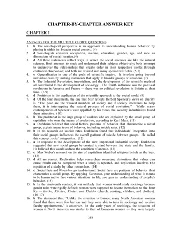
Thane Heins has made use of this fact by making a transformer like this:This style of transformer has got quite complicated magnetic flows when it is operating, although the diagramabove only shows some of the flow paths generated when the input coil “Coil 1” is pulsed. The really interestingresult is seen when that input pulse cuts off and we expect return magnetic flow from coil 2 and coil 3. Whathappens is this:Assume that coil 2 and coil 3 are identical. The reverse magnetic flux coming out of coil 2 immediatelyencounters a junction with one path being far easier to use than the other. As a result, the vast majority of thatmagnetic flow follows the broad path, and only a small percentage flows through the narrow path. The broad pathflow meets and is opposed by an identical large flow coming from coil 3, and those flows effectively cancel eachother out. This produces a major improvement over an ordinary transformer. But, the small flow reaching theentrance to Coil 1 encounters two identical paths, and only one of those paths goes to coil 1, so the flux divideswith half going towards coil 3 and half going through coil 1. That halves the strength of the already smallpercentage of the original, unwanted reverse magnetic flow into coil 1. The other half runs into the reduced flowfrom coil 3 and those halves cancel each other out. The overall effect is a really major improvement in theperformance of the transformer as a whole.In the patent document, Thane quotes a prototype test which had a primary coil winding with 2.5 ohms resistance,carrying 0.29 watts of power. The secondary coil 1 had a winding with 2.9 ohms resistance, receiving 0.18 wattsof power. The Resistive load 1 was 180 ohms, receiving 11.25 watts of power. The secondary coil 2 had awinding with 2.5 ohms resistance, and received 0.06 watts of power. Resistive load 2 was 1 ohm, receiving 0.02watts of power. Overall, the input power was 0.29 watts and the output power 11.51 watts, which is a COP of39.6 and while the document does not mention it directly, the primary coil should be driven at it's resonantfrequency.3-4
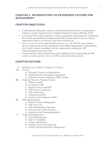
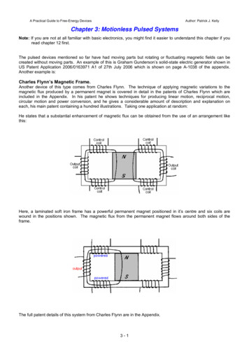
A variation of this arrangement is to attach an outer toroid to the existing bi-toroid arrangement, like this:This prototype, as you can see, is fairly simple construction, and yet, given an input power of 106.9 milliwatts, itproduces an output power of 403.3 milliwatts, which is 3.77 times greater.This is something which needs to be considered carefully. Conventional science say that "there is no such thingas a free meal" and with any transformer, you will get less electrical power out of it than you put into it. Well, thissimple looking construction demonstrates that this is not the case, which shows that some of the dogmaticstatements made by present day scientists are completely wrong.At https://youtu.be/-LBnnL4v8MQ?list PLkH1zLdXy1Sy3 St1tUwtY 6qiusDkyG9 Thane shows a video where hisbi-toroidal transformer is constructed from three ordinary toroids held together with cable ties:Thane then goes on to demonstrate the performance of this combination:3-5
The LED associated with the power being fed to the primary winding is so low that no light is visible. The outputLED is lit so powerfully that the camera has difficulty in displaying it. The dummy load is a single resistor placedacross the third winding and there is a major performance difference when it is plugged into place. This videodemonstrates very clearly, the difference caused by using a bi-toroidal transformer.This simple and elegant modification of the humble transformer, converts it into a free-energy device which booststhe power used to drive it and outputs much greater power. Congratulations are due to Thane for this techniqueand for his sharing it openly with anyone who is interested.The High-power Motionless Generator of Clemente FigueraIn 2012 a contributor who uses the ID ‘Wonju-Bajac’ started a forum to investigate the work of Clemente Figueraat eel-part1-clemente d member ‘hanlon1492’ contributed enormously by producing English translations of Figuera’s patents.Clemente Figuera of the Canary Islands died in 1908. He was a highly respected individual, an Engineer andUniversity Professor. He was granted several patents and was known to Nikola Tesla. Figuera’s design is verysimple in outline.In 1902 the Daily Mail announced that Mr. Figuera, a Forestry Engineer in the Canary Islands, and for many yearsProfessor of Physics at St. Augustine’s College, Las Palmas, had invented a generator which required no fuel.Señor Figuera has constructed a rough apparatus by which, in spite of it’s small size and it’s defects, he obtains550 volts, which he utilises in his own house for lighting purposes and for driving a 20 horse-power motor.The Figuera Device looks like a complicated transformer, but in fact, it isn’t. Instead, it is two sets of sevenopposing electromagnets with an output coil positioned between each opposing pair of electromagnets. Thephysical position of the electromagnets and output coils is important as they are positioned very close to eachother and there are induced magnetic fields between adjacent electromagnets and between the output coils dueto their close proximity.The two sets of electromagnets are wound with very low-resistance, high-current wire or possibly, even with thickfoil. The information given in the Figuera patent states that the electromagnets will be referred to in the patent bythe letters “N” and “S” and it is now thought that those two letters are deliberately misleading as people tend tothink of those letters referring to “North magnetic pole” and “South magnetic pole” while in reality, theelectromagnets almost certainly oppose each other, that is, with North poles facing each other or possibly, withSouth poles facing each other. The arrangement is believed to be like this when seen from above:3-6
This arrangement creates a magnetic Bloch wall (or magnetically null point) in the centre of the yellow output coilsand the position of that magnetic balance point is very easily moved if the power suppl
Chapter 3: Motionless Pulsed Systems Note: If you are not at all familiar with basic electronics, you might find it easier to understand this chapter if you read