Transcription
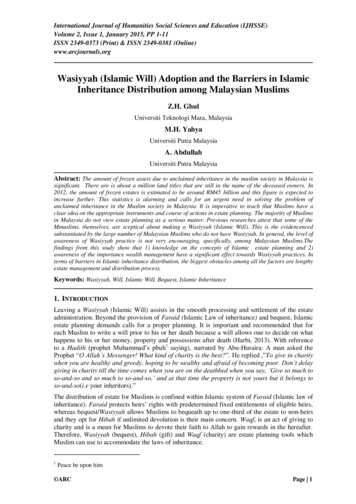
PDH Course E426 (3 PDH)Voltage Drop CalculationsØZI*XI*ErrorDavid A. Snyder, PEI*RØ2014Enlarged from BelowCircle with RadiusVs (Line-to-Neutral)ltage (Vs)Sending VoReceiver Voltage (Vr)ZI*I*XOrigin of CircleØI*Ø 32 cos Ø 0.848sin Ø 0.53ErrorRIRcosØ IXsinØEstimated VdropActual VdropPhasor Diagram of Voltage Relations for Voltage-Drop CalculationsFigure xyz18012345PDH Online PDH Center5272 Meadow Estates DriveFairfax, VA 22030-6658Phone & Fax: 703-988-0088www.PDHonline.orgwww.PDHcenter.comAn Approved Continuing Education Provider67
www.PDHcenter.comPDH Course E426www.PDHonline.orgVoltage Drop CalculationsDavid A. Snyder, PETable of ContentsIntroduction . 4Table 1 – Quick Guide to Voltage Drop Formulas . 5Voltage Drop and the National Electrical Code . 5Branch Circuits . 5Feeders . 6Sensitive Electronic Equipment . 6Other Considerations . 6Common Formulas for Voltage Drop Calculations . 6Single-Phase Approximate Voltage Drop Formulas . 7Figure 1 – Single-Phase, Two-Wire Voltage-Drop Circuit Diagram . 7Figure 2 – Distributed Resistance in Conductors. 8Table 2 – Derivation of the Value of K for Copper Conductors. 10Figure 3 – Single-Phase, Three-Wire Voltage-Drop Circuit Diagram . 11Three-Phase Approximate Voltage Drop Formulas . 11Figure 4 – Three-Phase Wye-Connected with Neutral Voltage-Drop Circuit Diagram . 12No Neutral Current in a Balanced Three-Phase System? . 14Figure 5 – Balanced, Wye-Connected, Three-Phase, Resistance Load, with NeutralConnection . 15Figure 6 – Balanced, Wye-Connected, Three-Phase 10 KW Load at 480 V. 15 3 Relationship of Three-Phase Voltages . 16Figure 7 – 480Y/277V Wye-Delta Voltage Relationship . 16Figure 8 –Wye-Delta Voltage Relationship – Right Triangle Geometry . 17Figure 9 – 208Y/120V Wye-Delta Voltage Relationship . 18Why the 3 Is Used in Balanced, Three-Phase Voltage Drop Calculations . 18Figure 10 – The Square Root of Three in Three-Phase Voltage-Drop Calculations . 19Table 9 in the NEC . 20Which Columns Are Applicable? . 20XL (Reactance) . 20Alternating-Current Resistance. 20Effective Z at 0.85 PF . 20Table 3 – Selected Effective Z Calculations at 0.85 PF (Ohms-to-Neutral per 1,000 feet) . 21Effective Z at Any Power Factor: Note 2 to Table 9 in the NEC . 21Table 4 – Effective Z Calculations for Selected Wire Sizes at Various Power Factors(Ohms-to-Neutral per 1,000 feet). 22Note 2 to Table 8 in the NEC. 23Phasor Diagrams of Resistance, Reactance, and Impedance for Conductors . 24Figure 11 – Phasor Diagram of Resistance, Reactance, and Impedance for 12 AWG CopperConductors in Steel Conduit at 0.85 PF . 25Figure 12 – Phasor Diagram of Resistance, Reactance, and Impedance for 12 AWG CopperConductors in Steel Conduit at Selected Power Factor Values . 26 2014 David A. SnyderPage 2 of 57
www.PDHcenter.comPDH Course E426www.PDHonline.orgFigure 13 – Phasor Diagram of Resistance, Reactance, and Impedance for 250 KCMILCopper Conductors in Steel Conduit at 0.85 PF . 26Figure 14 – Phasor Diagram of Resistance, Reactance, and Impedance for 500 KCMILCopper Conductors in Steel Conduit at 0.85 PF . 27Figure 15 – Phasor Diagram of Resistance, Reactance, and Impedance for 500 KCMILCopper Conductors in Steel Conduit at Selected Power Factor Values . 27Estimated Vdrop Derived from Impedance Phasor Diagrams. 28Figure 16 – Applying 300 Amps to the Impedance Phasor Diagram for 500 KCMIL CopperConductors in Steel Conduit at Selected Power Factor Values . 28Estimated Vdrop, Single-Phase: . 29Estimated Vdrop, Three-Phase: . 29Voltage Drop Phasor Diagram in IEEE Standard 141 (Red Book) . 30Figure 17 – IEEE Phasor Diagram of Voltage Drop . 30Figure 18 – Vertical Components of Phasor Diagram of Voltage Drop . 31Figure 19 – Triangle Formed by Vs, Vr Estimated Vdrop, and IXcosΦ-IRsinΦ . 32Figure 20 – When the Vector I * Z Really Is the Actual Vdrop . 32Figure 21 – If Conductor X R, the Error Increases as Power Factor Increases . 33Calculating the Error Shown in the IEEE Phasor Diagram . 34Figure 22 – Finding the Height h of a Circular Segment . 34Single-Phase Formulas for Error and Actual Vdrop:. 36Three-Phase Formulas for Error and Actual Vdrop: . 36Table 5 – Error Voltage Drop Calculations for Real-World Examples in Next Section . 37Real-World Examples . 38Table 6 – Real-World Examples . 3810 Hp Motor at 480V/3Φ with 12 AWG Conductors. 38Figure 23 – Line-to-Neutral Voltage Drop for 10 Hp Motor at 480V/3Φ with 200’ of12 AWG Conductors. 39Table 7 – Line-to-Line Voltage Drop for 10 Hp Motor at 480V/3Φ with 200’ of 12 AWGConductors . 4015 KW Heater at 480V/3Φ with 10 AWG Conductors . 41Figure 24 – Line-to-Neutral Voltage Drop for 15 KW Load at 480V/3Φ with 200’ of10 AWG Conductors. 41Table 8 – Line-to-Line Voltage Drop for 15 KW Load at 480V/3Φ with 200’ of 10 AWGConductors . 42250 Hp Motor at 480V/3Φ with 500 KCMIL Conductors . 43Figure 25 – Line-to-Neutral Voltage Drop for 250 Hp Motor at 480V/3Φ with 200’ of500 KCMIL Conductors . 43Table 9 – Line-to-Line Voltage Drop for 250 Hp Motor at 480V/3Φ with 200’ of500 KCMIL Conductors . 44Rearranging the Formulas Used for Approximate Vdrop. 45Single-Phase Voltage Drop Formulas – Rearranged . 45Table 10 – Voltage Drop for 10 A Load at 120V/1Φ with 100’ of 10 AWG Conductors . 47Three-Phase Voltage Drop Formulas – Rearranged . 49Other Considerations . 51Increase Equipment Grounding Conductor Size . 51Increase Grounded (Neutral) Conductor Size . 52 2014 David A. SnyderPage 3 of 57
www.PDHcenter.comPDH Course E426www.PDHonline.orgVerify Wire Size and Quantity Capacity of Terminations at Both Ends . 52Verify Conduit Size . 52Rule-of-Thumb . 53Converting Formulas from Single-Phase to Three-Phase. 53Table 11 – Voltage Drop for 10 A Load at 120V/1Φ with 120’ of 12 AWG Conductors . 54Table 12 – Voltage Drop for 10 A Load at 208V/3Φ with 208’ of 12 AWG Conductors . 54Table 13 – Voltage Drop for 10 A Load at 277V/1Φ with 277’ of 12 AWG Conductors . 55Table 14 – Voltage Drop for 10 A Load at 480V/3Φ with 480’ of 12 AWG Conductors . 55In Closing . 56Abbreviations . 56Additional Reading . 56IntroductionVoltage drop calculations are an everyday occurrence, but the method used and the level of detailcan vary widely, based on the person performing the calculation and on the required accuracy.A few caveats about this course and quiz: Voltages are RMS.Topics that are not covered in this course: All power factors are lagging. Aluminum conductors, since the conceptsare the same as for copper conductors. All conductors are stranded. Direct-current (DC) systems. Ambient temperatures for conductors arebetween 30 C and 40 C, unless statedotherwise. Termination temperatures are75 C, unless otherwise indicated. Leading power factor. The term ‘resistance’ is used sometimes inthis course to refer to impedance. Metric units. Voltage drop for fire pumps. Voltages greater than 600 V. The Greek letters ϕ (phi) and θ (theta) are used interchangeably in other technicalpublications to represent the angle between the current and voltage in alternating-currentsystems. In other words, some sources say the power factor PF cos(ϕ) and others usePF cos(θ). Three-phase voltages are counter-clockwise, rotating A, B, C in vector space. This course has several scaled drawings or figures. When printing a PDF with scaleddrawings, choose “Actual Size” or a “Custom Scale” of 100% for accurate results. TheReader is encouraged to use a decimal scale or ruler (the decimal edge of a framingsquare will do, in a pinch) to measure the results illustrated in the scaled figures.We will start with well-known formulas for approximate voltage drop (Vdrop), then EstimatedVdrop, then derive the formula for exact or Actual Vdrop. As we shall see, someapproximations of voltage drop are more approximate than others. 2014 David A. SnyderPage 4 of 57
www.PDHcenter.comPDH Course E426www.PDHonline.orgThe first two types of formulas in single-phase sections and the three-phase sections are forapproximate voltage drop calculations. This is differentiated from estimated voltage dropcalculations in this course in order to point out that the Estimated Vdrop in the IEEE figures isnot based on the approximate voltage drop calculations. The estimated voltage drop is the thirdtype of formula.The fourth type of voltage drop formula is the Actual Vdrop formula.If you want to jump straight to the voltage drop formulas, here is a list of where they are located
www.PDHcenter.com PDH Course E426 www.PDHonline.org – - - -