Transcription
Modeling a 4G LTE System in MATLABIdin Motedayen-AvalSenior Applications EngineerMathWorksIdin.motedayen-aval@mathworks.com 2012 The MathWorks, Inc.1
Agenda 4G LTE and LTE Advanced–––– True Global standardTrue Broadband mobile communicationsHow it was achieved?What are the challenges?MATLAB and communications system design– Modeling and simulation– Simulation acceleration– Path to implementation Case study:– Physical layer modeling of an LTE system in MATLAB Summary2
Modeling a 4G LTE System in MATLABPart 1:Modeling & simulation 2012 The MathWorks, Inc.3
4G LTE and LTE Advanced4
4G LTE and LTE AdvancedDistinguishing Features Motivation– Very high capacity & throughput– Support for video streaming, web browsing, VoIP, mobile apps A true global standard– Contributions from all across globe– Deployed in AMER, EMEA, APLA5
4G LTE and LTE AdvancedDistinguishing Features A true broadband mobile standard– From 2 Mbps (UMTS)– To 100 Mbps (LTE)– To 1 Gbps(LTE Advanced)6
How is this remarkable advance possible? Integration of enabling technologies with sophisticatedmathematical algorithms– OFDM– MIMO (multiple antennas)– Turbo Coding Smart usage of resources and bandwidth––––Adaptive modulationAdaptive codingAdaptive MIMOAdaptive bandwidth7
What MATLAB users care about LTE? Academics– Researchers contributing to future standards– Professors– Students Practitioners– System Engineers– Software designers– Implementers of wireless systems Challenge in interaction and cooperation between thesetwo groupsMATLAB is their common language8
Challenges:From specification to implementation Simplify translation fromspecification to a model asblue-print for implementationIntroduce innovativeproprietary algorithmsSystem-level performanceevaluationAccelerate large scalesimulationsAddress gaps in theimplementation workflow9
Where does MATLAB fit in addressing thesechallenges? MATLAB and CommunicationsSystem Toolbox are ideal for LTEalgorithm and system designMATLAB and Simulink provide anenvironment for dynamic & largescale simulationsAccelerate simulation with avariety of options in MATLABConnect system design toimplementation with– C and HDL code generation– Hardware-in-the-loop verification10
Communications System ToolboxOver 100 algorithms for– Modulation, Interleaving, Channels, Source Coding– Error Coding and Correction– MIMO, Equalizers, Synchronization– Sources and Sinks, SDR hardwareAlgorithm libraries in MATLABAlgorithm libraries in Simulink11
4G LTE and LTE AdvancedExisting demos ofCommunications System toolboxWork in-progress12
Case Study:Downlink physical layer of LTE (Release apperScramblingantenna portsModulationmapperResource elementmapperOFDM signalgenerationResource elementmapperOFDM signalgenerationPrecoding 2012 The MathWorks, Inc.13
What we will do today1. Start modeling in MATLAB2. Iteratively incorporate components such as Turbo Coding,MIMO, OFDM and Link Adaptation3. Put together a full system model with MATLAB & Simulink4. Accelerate simulation speed in MATLAB5. Path to implementation14
Modeling and Simulation 2012 The MathWorks, Inc.15
LTE Physical layer model in standard Downlink Shared Channel– Transport channel– Physical channelTurbo ChannelCodingMIMOOFDMAAdaptationof everythingReference: 3GPP TS 36 211 v10 (2010-12)16
LTE Physical layer model in MATLABTurbo ptationof enna portsModulationmapperResource elementmapperOFDM signalgenerationResource elementmapperOFDM signalgenerationPrecoding17
LTE Physical layer model in MATLAB Open LTE system modelTurbo ptationof enna portsModulationmapperResource elementmapperOFDM signalgenerationResource elementmapperOFDM signalgenerationPrecoding18
Overview of Turbo Coding Error correction & codingtechnology of LTE Performance: Approachchannel capacity (Shannonbound) Evolution of convolutionalcoding Based on an iterativedecoding scheme19
MATLAB Demo comm.ConvolutionalEncoder( comm.ViterbiDecoder( „InputFormat‟, „Hard‟, 20
MATLAB Demo ikelihood ratio‟ comm.ViterbiDecoder „InputFormat‟, „Soft‟, 21
MATLAB Demo comm.TurboEncoder ikelihood ratio‟ comm.TurboDecoder( „NumIterations‟, 6, 22
DL-SCH transport channel processinga0 , a1 ,., a A 1Transport blockCRC attachmentb0 , b1 ,., bB 1Code block segmentationCode block CRC attachmentcr 0 , cr1 ,., cr K r 1 Channel codingd r(i0) , d r(1i ) ,., d r(i )Dr 1 Rate matchinger 0 , er1 ,., er Er 1 Code blockconcatenationf 0 , f1 ,., f G 13GPP TS 36.212 v10.0.0 commpccc23
Downlink Shared Channel - transport channela0 , a1 ,., a A 1Transport blockCRC attachmentb0 , b1 ,., bB 1Turbo ChannelCodingMATLAB Function blockCode block segmentationCode block CRC attachmentcr 0 , cr1 ,., cr K r 1 Channel codingd r(i0) , d r(1i ) ,., d r(i )Dr 1 Rate matchinger 0 , er1 ,., er Er 1 Code blockconcatenationf 0 , f1 ,., f G 124
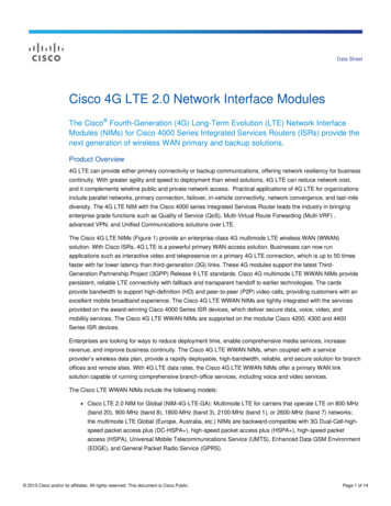
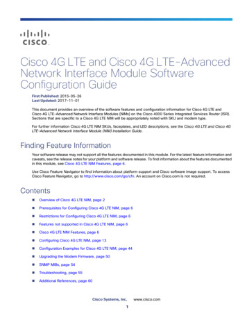
OFDM Overview Orthogonal Frequency Division Multiplexing– Multicarrier modulation scheme (FFT-based) Split available spectrum into uniform intervals called sub-carriers– Transmit data independently at each sub-carrier Most important feature– Robust against multi-path fading– Using low-complexity frequency-domain equalizers25
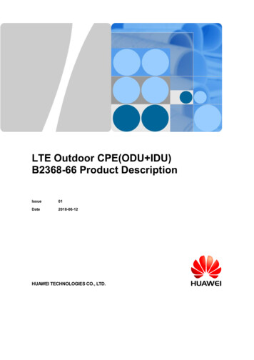
OFDM & Multi-path Fading Multi-path propagation leads to frequency selective fadingFrequency-domain equalization is less complex and perfectlymatches OFDMWe need to know channel response at each sub-carrier – pilotsH(ω)*ℎ2 , 𝑑2 }Frequency-selective fadingG(ω)H(ω)Multi-path1*ℎ0 , 𝑑0 }*ℎ1 , 𝑑1 }y(n) 𝑁𝑛 0 ℎ𝑛ωx( 𝑛 𝑑𝑛 )𝑌(𝜔) 𝐻 𝜔 𝑋(𝜔)Frequency-domain equalizationIf G(ω𝑘 ) 𝐻 1 (ω𝑘 )ωG(ω𝑘 ) Y(ω𝑘 ) 𝑋(ω𝑘 )26
How Does LTE Implement OFDM?FrequencyNmax 2048 otsResourceblockInterpolatehorizontally (Time)Resourcegrid 0.511.52Time (msec)27
How to Implement LTE OFDM in MATLABDepending onChannel BandwidthswitchprmLTEPDSCH.NrbCase 25, N 512; 6*numRb mod(v vsh, 6) 1;Transmitter:Place pilots in regular intervalsSet Frequency-domainFFT sizeCase 100, N 2048; mean([hp(:,1,1,n) hp(:,3,1,n)]) mean([hp(k,2,1,:) hp(k,4,1,:)])X ifft(tmp,N,1);Create OFDM signalReceiver:Estimate channel byinterpolating in time &frequency28
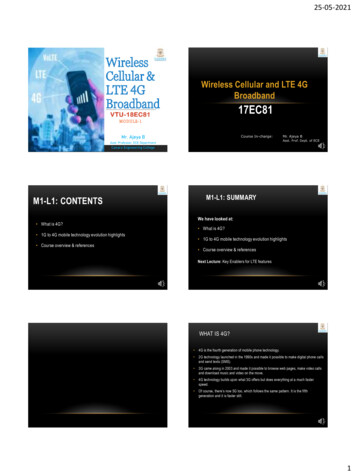
MIMO Overview Multiple Input Multiple OutputUsing multiple transmit and receiveantennasY H*X nh1,1h2,1H tiple InputMultiple Output29
Where is MIMO being used? Several wireless standards–––– 802.11n: MIMO extensions of WiFi as of 2008802.16e: As of 2005 in WiMax Standard3G Cellular: 3GPP Release 6 specifies transmit diversity mode4G LTETwo main types of MIMO– Spatial multiplexing– Space-Time Block Coding (STBC)30
Space-Time Block Codes (STBC) STBCs insert redundant data at transmitterImproves the BER performanceAlamouti code (2 Tx, 2 Rx) is one of simplestexamples of orthogonal STBCs31
Spatial Multiplexing MIMO technique used in LTE standard Divide the data stream into independent sub-streamsand use multiple transmit antennas MIMO is one of the main reasons for boost in data rates– More transmit antennas leads to higher capacity MIMO Receiver essentially solves this system of linearequations𝑌 𝐻𝑋 𝑛32
MIMO-OFDM overviewY 𝐻 𝑋 𝑛What if 2 rows arelinearly dependent?𝐻 ℎ43ℎ4ℎ4ℎ34ℎ44Dimension 4; Rank 3;H singular (not invertible)Y𝐻 𝑈𝐷𝑉 𝐻subcarrier 𝑤𝑘Singular Value DecompositionTime 𝑡𝑛To avoid singularity:1. Precode input with pre-selected V2. Transmit over antennas based on Rank33
Adaptive MIMO:Closed-loop Pre-coding and Layer MappingBase stationLayerMappingPrecoding(*)Rank IndicatorPrecoder Matrix IndicatorOFDMChannel RankEstimationPrecoder MatrixEstimationmobile34
Adaptive MIMO in MATLAB In Receiver:Detect V Rank of the H Matrix V prmLTEPDSCH.numLayers; Number of layersSwitch V In Transmitter: (next frame)Based on number of layersFill up transmit antennas withavailable rankcase 4out complex(zeros(inLen1/2, v));out(:,1:2) reshape(in1, 2,inLen1/2).';out(:,3:4) reshape(in2, 2,inLen2/2).';35
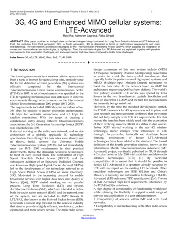
Cell-Specific Reference Signal Mapping Null transmissions allow for separable channel estimation at RxUse clustering or interpolation for RE channel estimationFigure 6.10.1.2-1, 3GPP TS 36.211 v10.0.0One antenna portR0R0R04 CSR, 0 nulls /slot /RB 8 CSR/160 RER0R0R0R0R0l 0l 6 l 0l 6Resource element (k,l)Two antenna portsR0R0R0R0R1R0R0R0Four antenna portsR0R0l 0R0odd-numbered slotsAntenna port 0l 0R2R1even-numbered slotsodd-numbered slotsAntenna port 1R3R2l 6l 04 CSR, 8 nulls /slot /RB 8 CSR / 144 RER3R2R1l 6 l 0Varies per antenna port:R3R2R1R1l 6l 6R1R1R0l 6 l 0even-numbered slotsR1R1R0Reference symbols on this antenna portl 6 l 0R1R0R0l 0l 64 CSR, 4 nulls /slot /RB 8 CSR /152 RENot used for transmission on this antenna portR1R1l 6 l 0R0R1R1R0l 0R1R1R3l 6 l 0even-numbered slotsl 6odd-numbered slotsAntenna port 2l 0l 6 l 0even-numbered slotsl 62 CSR, 10 nulls /slot /RB 4 CSR / 144 REodd-numbered slotsAntenna port 336
Link Adaptation Overview Examples of link adaptations– Adaptive modulation QPSK, 16QAM, 64QAM– Adaptive coding Coding rates from (1/13) to (12/13)– Adaptive MIMO 2x1, 2x2, ,4x2, , 4x4, 8x8– Adaptive bandwidth Up to 100 MHz (LTE-A)37
LTE Physical layer model in MATLABTurbo ChannelCodingMIMOOFDMAAdaptationof everything38
Put it all together 39
References Standard documents – 3GPP link 3GPP TS 36.{201, 211, 212, 213, 101, 104, 141}, Release 10.0.0, (2010-12).3GPP TS 36.{201, 211, 212, 213, 101, 104}, Release 9.0.0, (2009-12). Books Dahlman, E.; Parkvall, S.; Skold, J., “4G LTE/LTE-Advanced for Mobile Broadband”, Elsevier,2011.Agilent Technologies, “LTE and the evolution to 4G Wireless: Design and measurementchallenges”, Agilent, 2009. Selected papers Min Zhang; Shafi, M.; Smith, P.J.; Dmochowski, P.A., “Precoding Performance with CodebookFeedback in a MIMO-OFDM System”, Communications (ICC), 2011 IEEE InternationalConference on, pp. 1-6. Simonsson, A.; Qian, Y.; Ostergaard, J., “LTE Downlink 2X2 MIMO with Realistic CSI: Overviewand Performance Evaluation”, 2010 IEEE WCNC, pp. 1-6.40
Summary MATLAB is the ideal language for LTEmodeling and simulationCommunications System Toolbox extendbreadth of MATLAB modeling toolsYou can accelerate simulation with avariety of options in MATLAB– Parallel computing, GPU processing,MATLAB to C Address implementation workflow gapswith– Automatic MATLAB to C/C and HDLcode generation– Hardware-in-the-loop verification41
Modeling a 4G LTE System in MATLABPart 2:Simulation acceleration 2012 The MathWorks, Inc.42
Why simulation acceleration? From algorithm exploration to system design– Size and complexity of models increases– Time needed for a single simulation increases– Number of test cases increases– Test cases become larger Need to reduce simulation time during design Need to reduce time for large scale testing duringprototyping and verification43
MATLAB is quite fast Optimized and widely-used libraries– BLAS: Basic Linear Algebra Subroutines (multithreaded)– LAPACK: Linear Algebra Package JIT (Just In Time) Acceleration– On-the-fly multithreaded code generation for increased speed Built-in support for vector and matrix operations Parallel computing support to utilize additional cores– Parallel Computing Toolbox– MATLAB Distributed Computing Server– GPU support44
Simulation acceleration options in MATLABSystemObjectsUser’s CodeParallelComputing DemocommaccelerationMATLAB to CGPUprocessing45
Parallel Simulation RunsWorkerTOOLBOXESWorkerBLOCKSETSWorkerWorkerTask 1Task 2Time DemoTask 3Task 4Time46
Summary matlabpool available workersNo modification of algorithmUse parfor loop instead of for loopParallel computation or simulationleads to further accelerationMore cores more speed47
Simulation acceleration options in MATLABSystemObjectsUser’s CodeParallelComputingMATLAB to CGPUprocessing48
What is a Graphics Processing Unit (GPU) Originally for graphics acceleration, now also used forscientific calculations Massively parallel array of integer andfloating point processors– Typically hundreds of processors per card– GPU cores complement CPU cores Dedicated high-speed memory49
Why would you want to use a GPU? Speed up execution of computationally intensivesimulationsFor example:– Performance: A\b with Double Precision50
Options for Targeting GPUs2) Execute MATLAB functions elementwiseon the GPUGreater ControlEase of Use1) Use GPU with MATLAB built-in functions3) Create kernels from existing CUDA codeand PTX files51
Data Transfer between MATLAB and GPU% Push data from CPU to GPU memoryAgpu gpuArray(A)% Bring results from GPU memory back to CPUB gather(Bgpu)52
GPU Processing withCommunications System ToolboxAlternative implementationfor many System objectstake advantage of GPUprocessingGPU System objects Use Parallel ComputingToolbox to execute manycommunications algorithmsdirectly on the GPUcomm.gpu.AWGNChannel Easy-to-use syntax Dramatically acceleratesimulations pu.LDPCDecodercomm.gpu.PSKDemodulator53
Example: Turbo Coding Impressive coding gainHigh computational complexityBit-error rate performance as a function of number ofiterations comm.TurboDecoder( „NumIterations‟, numIter, 54
Acceleration with GPU System objects Same numerical resultsVersionElapsed time AccelerationCPU8 hours1.01 GPU40 minutes12.0Cluster of 4GPUs11 minutes43.0 comm.TurboDecoder( comm.gpu.TurboDecoder( „NumIterations‟,„NumIterations‟, N, N, comm.AWGNChannel( comm.gpu.AWGNChannel( 55
Key Operations in Turbo Coding FunctionCPUGPU Version 1% Turbo EncoderhTEnc 4, [13 15], 13),.'InterleaverIndices', intrlvrIndices)% AWG NoisehAWGN comm.AWGNChannel('NoiseMethod', 'Variance');% BER measurementhBER comm.ErrorRate;% Turbo DecoderhTDec comm.TurboDecoder( 'TrellisStructure',poly2trellis(4, [13 15], 13),.'InterleaverIndices', intrlvrIndices,'NumIterations', numIter);ber zeros(3,1); %initialize BER output%% Processing loopwhile ( ber(1) MaxNumErrs && ber(2) MaxNumBits)data randn(blkLength, 1) 0.5;% Encode random data bitsyEnc step(hTEnc, data);%Modulate, Add noise to real bipolar datamodout 1-2*yEnc;rData step(hAWGN, modout);% Convert to log-likelihood ratios for decodingllrData (-2/noiseVar).*rData;% Turbo DecodedecData step(hTDec, llrData);% Calculate errorsber step(hBER, data, decData);end% Turbo EncoderhTEnc 4, [13 15], 13),.'InterleaverIndices', intrlvrIndices)% AWG NoisehAWGN comm.AWGNChannel('NoiseMethod', 'Variance');% BER measurementhBER comm.ErrorRate;% Turbo DecoderhTDec comm.gpu.TurboDecoder( 'TrellisStructure',poly2trellis(4, [13 15], 13),.'InterleaverIndices', intrlvrIndices,'NumIterations', numIter);ber zeros(3,1); %initialize BER output%% Processing loopwhile ( ber(1) MaxNumErrs && ber(2) MaxNumBits)data randn(blkLength, 1) 0.5;% Encode random data bitsyEnc step(hTEnc, data);%Modulate, Add noise to real bipolar datamodout 1-2*yEnc;rData step(hAWGN, modout);% Convert to log-likelihood ratios for decodingllrData (-2/noiseVar).*rData;% Turbo DecodedecData step(hTDec, llrData);% Calculate errorsber step(hBER, data, decData);end56
Profile results in Turbo Coding FunctionCPUGPU Version 1% Turbo Encoder 0.01 hTEnc 4, [13 15], 13),.'InterleaverIndices', intrlvrIndices)% AWG Noise 0.01 hAWGN comm.AWGNChannel('NoiseMethod', 'Variance');% BER measurement 0.01 hBER comm.ErrorRate;% Turbo Decoder 0.01 hTDec comm.TurboDecoder( 'TrellisStructure',poly2trellis(4, [13 15], 13),.'InterleaverIndices', intrlvrIndices,'NumIterations', numIter);% Turbo Encoder 0.01 hTEnc 4, [13 15], 13),.'InterleaverIndices', intrlvrIndices)% AWG Noise 0.01 hAWGN comm.AWGNChannel('NoiseMethod', 'Variance');% BER measurement 0.01 hBER comm.ErrorRate;% Turbo Decoder0.02 hTDec comm.gpu.TurboDecoder( 'TrellisStructure',poly2trellis(4, [13 15], 13),.'InterleaverIndices', intrlvrIndices,'NumIterations', numIter); 0.01 ber zeros(3,1); %initialize BER output%% Processing loopwhile ( ber(1) MaxNumErrs && ber(2) MaxNumBits)0.30data randn(blkLength, 1) 0.5;% Encode random data bits2.33yEnc step(hTEnc, data);%Modulate, Add noise to real bipolar data0.05modout 1-2*yEnc;1.50rData step(hAWGN, modout);% Convert to log-likelihood ratios for decoding0.03llrData (-2/noiseVar).*rData;% Turbo Decode330.54decData step(hTDec, llrData);% Calculate errors0.17ber step(hBER, data, decData);end 0.01 ber zeros(3,1); %initialize BER output%% Processing loopwhile ( ber(1) MaxNumErrs && ber(2) MaxNumBits)0.28data randn(blkLength, 1) 0.5;% Encode random data bits2.38yEnc step(hTEnc, data);%Modulate, Add noise to real bipolar data0.05modout 1-2*yEnc;1.45rData step(hAWGN, modout);% Convert to log-likelihood ratios for decoding0.04llrData (-2/noiseVar).*rData;% Turbo Decode98.18decData step(hTDec, llrData);% Calculate errors0.17ber step(hBER, data, decData);end57
Key Operations in Turbo Coding FunctionCPUGPU Version 2% Turbo EncoderhTEnc 4, [13 15], 13),.'InterleaverIndices', intrlvrIndices)% AWG NoisehAWGN comm.AWGNChannel('NoiseMethod', 'Variance');% BER measurementhBER comm.ErrorRate;% Turbo DecoderhTDec 4, [13 15], 13),.'InterleaverIndices', intrlvrIndices,'NumIterations', numIter);%% Processing loopwhile ( ber(1) MaxNumErrs && ber(2) MaxNumBits)data randn(blkLength, 1) 0.5;% Encode random data bitsyEnc step(hTEnc, data);%Modulate, Add noise to real bipolar datamodout 1-2*yEnc;rData step(hAWGN, modout);% Convert to log-likelihood ratios for decodingllrData (-2/noiseVar).*rData;% Turbo DecodedecData step(hTDec, llrData);% Calculate errorsber step(hBER, data, decData);end% Turbo EncoderhTEnc 4, [13 15], 13),.'InterleaverIndices', intrlvrIndices)% AWG NoisehAWGN comm.gpu.AWGNChannel ('NoiseMethod', 'Variance');% BER measurementhBER comm.ErrorRate;% Turbo Decoder - setup for Multi-frame or Multi-user processingnumFrames 30;hTDec lis(4, [13 15], 13),.'InterleaverIndices', intrlvrIndices,'NumIterations',numIter, ’NumFrames’,numFrames);%% Processing loopwhile ( ber(1) MaxNumErrs && ber(2) MaxNumBits)data randn(numFrames*blkLength, 1) 0.5;% Encode random data bitsyEnc gpuArray(multiframeStep(hTEnc, data, numFrames));%Modulate, Add noise to real bipolar datamodout 1-2*yEnc;rData step(hAWGN, modout);% Convert to log-likelihood ratios for decodingllrData (-2/noiseVar).*rData;% Turbo DecodedecData step(hTDec, llrData);% Calculate errorsber step(hBER, data, gather(decData));end58
Profile results in Turbo Coding FunctionCPU% Turbo Encoder 0.01 hTEnc 4, [13 15], 13),.'InterleaverIndices', intrlvrIndices)% AWG Noise 0.01 hAWGN comm.AWGNChannel('NoiseMethod', 'Variance');% BER measurement 0.01 hBER comm.ErrorRate;% Turbo Decoder 0.01 hTDec comm.TurboDecoder( 'TrellisStructure',poly2trellis(4, [13 15], 13),.'InterleaverIndices', intrlvrIndices,'NumIterations', numIter);%% Processing loopwhile ( ber(1) MaxNumErrs && ber(2) MaxNumBits)0.30data randn(blkLength, 1) 0.5;% Encode random data bits2.33yEnc step(hTEnc, data);%Modulate, Add noise to real bipolar data0.05modout 1-2*yEnc;1.50rData step(hAWGN, modout);% Convert to log-likelihood ratios for decoding0.03llrData (-2/noiseVar).*rData;% Turbo Decode330.54decData step(hTDec, llrData);% Calculate errors0.17ber step(hBER, data, decData);endGPU Version 2% Turbo Encoder 0.01 hTEnc 4, [13 15], 13),.'InterleaverIndices', intrlvrIndices)% AWG Noise0.03 hAWGN comm.gpu.AWGNChannel ('NoiseMethod', 'Variance');% BER measurement 0.01 hBER comm.ErrorRate;% Turbo Decoder - setup for Multi-frame or Multi-user processing0.01 numFrames 30;0.01 hTDec comm.gpu.TurboDecoder('TrellisStructure', poly2trellis(4, [13 15], 13),'InterleaverIndices', intrlvrIndices,'NumIterations',numIter, ’NumFrames’,numFrames);%% Processing loopwhile ( ber(1) MaxNumErrs && ber(2) MaxNumBits)0.22data randn(numFrames*blkLength, 1) 0.5;% Encode random data bits2.45yEnc gpuArray(multiframeStep(hTEnc, data, numFrames));%Modulate, Add noise to real bipolar data0.02modout 1-2*yEnc;0.31rData step(hAWGN, modout);% Convert to log-likelihood ratios for decoding0.01llrData (-2/noiseVar).*rData;% Turbo Decode20.89decData step(hTDec, llrData);% Calculate errors0.09ber step(hBER, data, gather(decData));end59
Things to note when targeting GPU Minimize data transfer between CPU and GPU. Using GPU only makes sense if data size is large. Some functions in MATLAB are optimized and can befaster than the GPU equivalent (eg. FFT). Use arrayfun to explicitly specify elementwiseoperations.60
Acceleration Strategies Applied in MATLABOption1. Best Practices in Programming Vectorization & pre-allocation Environment tools. (i.e. Profiler, Code Analyzer)2. Better Algorithms Ideal environment for algorithm exploration Rich set of functionality (e.g. System objects)Technology /ProductMATLAB, Toolboxes,System ToolboxesMATLAB, Toolboxes,System Toolboxes3. More Processors or CoresParallel Computing High level parallel constructs (e.g. parfor, matlabpool) Toolbox,MATLAB Distributed Utilize cluster, clouds, and gridsComputing Server4. Refactoring the Implementation Compiled code (MEX) GPUs, FPGA-in-the-LoopMATLAB, MATLAB Coder,Parallel ComputingToolbox61
Summary MATLAB is the ideal language for LTEmodeling and simulationCommunications System Toolbox extendbreadth of MATLAB modeling toolsYou can accelerate simulation with avariety of options in MATLAB– Parallel computing, GPU processing,MATLAB to C Address implementation workflow gapswith– Automatic MATLAB to C/C and HDLcode generation– Hardware-in-the-loop verification62
Modeling a 4G LTE System in MATLABPart 3: Path to implementation (C and HDL) 2012 The MathWorks, Inc.63
LTE Downlink processingAdvancedchannel codingMIMOOFDMAdaptEverything64
Why Engineers translate MATLAB to C today?Integrate MATLAB algorithms w/ existing C environmentusing source code or static librariesPrototype MATLAB algorithms on desktops asstandalone executablesAccelerate user-written MATLAB algorithmsImplement C/C code on processors or hand-off tosoftware engineers65
i terateAutomatic Translation of MATLAB to CAlgorithm Design andCode Generation inMATLABverify/a ccelerateWith MATLAB Coder, design engineers can Maintain one design in MATLABDesign faster and get to C/C quicklyTest more systematically and frequentlySpend more time improving algorithms in MATLAB66
MATLAB Language Support forCode Generationvisualizationvariable-sized dataJavastructsparsefunctionsnumericSystem ted functionsclassesmallocgraphics67
Supported MATLAB LanguageFeatures and FunctionsBroad set of language features and functions/systemobjects supported for code generation. Matrices andArrays Matrix operationsN-dimensional arraysSubscriptingFramesPersistent variablesGlobal variablesData Types ProgrammingConstructsComplex numbers Arithmetic, relational,Integer mathandDouble/single-precisionlogical operatorsFixed-point arithmetic Program controlCharacters(if, for, while, switch )StructuresNumeric classesVariable-sized dataSystem objectsFunctions MATLAB functions and sub-functions Variable length argument lists Function handlesSupported algorithms 400 MATLAB operators andfunctions 200 System objects for Signal processing Communications Computer vision68
Path to implementation Bring it all to Simulink Elaborate your design––––Model System-level inaccuraciesCompensateAdd fixed-pointGenerate HDL69
MATLAB to Hardware 2012 The MathWorks, Inc.70
Why do we use FPGAs? Customized interfaces toperipherals High-speed communicationinterfaces to otherprocessorsMemoryMemoryMemoryWe are goingto focus onthis use casetodayBridgeAnalog I/O Finite state machines,digital logic, timing andmemory control High speed, highly parallelDSP AlgorithmsFPGAARMDigital I/ODSPDSPAlgorithms71
Separate Views of DSP ImplementationSystem DesignerFPGA DesignerAlgorithm DesignSystem Test BenchRTL DesignRTL VerificationFixed-PointEnvironment ModelsIP InterfacesBehavioral SimulationTiming and Control LogicAnalog ModelsHardware ArchitectureFunctional SimulationArchitecture ExplorationDigital ModelsStatic Timing AnalysisAlgorithms / IPAlgorithms / IPTiming SimulationImplement DesignFPGA RequirementsBack AnnotationSynthesisMapHardware SpecificationPlace & RouteTest StimulusHardware72
What we will learn todayMATLAB to Hardware Convert design to fixed-point– Use Fixed-point Tool– Use NumericTypeScope in MATLAB– Verify against floating-point design Serialize designImplementation using HDL Coder– Verify through software and/or hardware co-simulation73
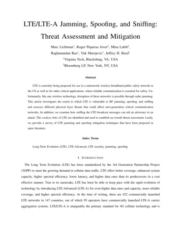
OFDM Transmitter74
MATLAB to Hardwareifft(x, 2048, 1) Issue #1––––– „x‟ is 2048x4 matrixMATLAB does 2048-pt FFT along first dimensionOutput is also 2048x4Cannot process samples this way in hardware!Serialize designIssue #2– MATLAB does double-precision floating-point arithmetic– Floating point is expensive in hardware (power and area)– Convert to fixed-point75
HDL Workflow Floating Point Model– Satisfies System Requirements SystemRequirementsExecutable Specification Model Elaboration– Develop Hardware Friendly Architecture in Simulink– Convert to Fixed-Point Determine Word LengthDetermine Binary Point LocationModelElaborationImplement Design– Generate HDL code using Simulink HDL Coder– Import Custom and Vendor IP Floating PointModelImplementCode GenerationContinuous Verification– MATLAB and/or Simulink ModelVerification– Software co-simulation with HDL simulator– Hardware co-simulationVerification78
Divide and conquerSave simulation data to use in development79
MATLAB-based FFT Can be doneResources– 120 LUTs (1%)– 32 Slices (1%)– 0 DSP48s Need 2048-point FFT32-point FFT chokessynthesis tool!80
Re-implement using Simulink blockscompare against original code81
Convert to fixed-pointcompare against original code82
What you just saw Simulink Fixed-Point tomodel fixed-point data types– Word lengths– Fraction lengths Fixed-Point Tool– monitoring signalmin/max, overflow– optimization ofdata types83
Use original testbench to optimize settings84
Analyze BER to determine word length Anything beyond8 bits is “goodenough”85
Recallifft(x, 2048, 1) Issue #1––––– „x‟ is 2048x4 matrixMATLAB does 2048-pt FFT along first dimensionOutput is also 2048x4Cannot process samples this way in hardware!Serialize designIssue #2– MATLAB does double-precision floating-point arithmetic– Floating point is expensive in hardware (power and area)– Convert to fixed-point86
Serial & Fixed-point“HDL ready”87
Automatically Generate HDL CodeSimulink HDL Coder88
What You Just Saw - Workflow AdvisorSelect ASIC, FPGA, Or FPGA Board TargetPrepare Model For HDL Code GenerationGenerate HDL CodePhysical Design and Critical Path HighlightingProgram FPGA89
What You Just Saw – Generated HDL CodeReadable, PortableHDL Code90
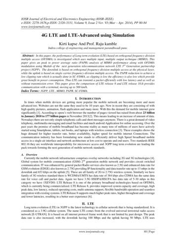
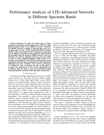
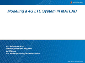
LTE Frame Structure (FDD)0.5 ms#0#1#2#3 .#1910ms 1 Frame 10ms10 sub-frames per frame2 slots per sub-frame (1 slot .5ms)7 OFDM symbols per slot– 2048 subcarriers in our simulation– IFFT output sample time0.5𝑚𝑠7 3.4877 10 8 𝑠 𝐎𝐑 28.672𝑀𝐻𝑧2048(30.72MHz after cyclic prefix)91
Frame and Slot Structure30.72 MHz 15000 * 204825 * cdma2000 8 * W-CDMA 30.72 MHz If we do 2048-length FFT, we can have 15 ofthem per millisecondBut we need a cyclic prefix Choose to have 14 symbols/ms (1 sub-frame) – Split into two slots of 7 symbols92
Review: Automatic HDL Code Generation Readable, portable HDL codeTarget ASIC and FPGAStandard Simulink librariesPush-button programming ofXilinx and Altera FPGAOptimize for area and speedCode traceability between modeland code93
FPGA Prototyping Shorter iteration cycles– Automatic HDL code generation– Integrated HDL verificationMATLAB and Simulink System and Algorithm DesignBehavioral Simulation Flexible automatic HDLCode generationSynthesizableRTLBack Annotation–––––Speed OptimizationArea OptimizationPower saving optionsResource utilizationValidation modelsImplement DesignSynthesisMapPlace & RouteVerificationFunctional SimulationStatic Timing AnalysisTiming SimulationFPGA Hardware94
HDL CoderGenerate VHDL and Verilog Code for FPGA and ASIC designsNew: MATLAB to HDLMATLABSimulinkHDLCoderVerilog and VHDL Automatic floating-point tofixed-point conversion HDL resource optimizationsand reports Algorithm-to-HDL traceability Integration with simulation &synthesis tools95
HDL VerifierVerify VHDL and Verilog code using cosimulation and FPGAsMATLABSimulinkNew:FPGA Hardware-in-the Loop VerificationHDLVerifierModelSim and Incisive Xilinx and Altera boards Support for 15 Altera andXilinx FPGA boards Use with: HDL CoderHand-written HDL code96
HDL Workflow Floating Point Model– Satisfies System Requirements SystemRequi
MATLAB is the ideal language for LTE modeling and simulation Communications System Toolbox extend breadth of MATLAB modeling tools You can accelerate simulation with a variety of options in MATLAB - Parallel computing, GPU processing, MATLAB to C Address implementation workflow gaps with - Automatic MATLAB to C/C and HDL