Transcription
Installation & Operation ManualITC-FS 1 & 2 CircuitHeat Trace Controller forFire Suppression SystemsPK543-20037-75525November 20201
Table of ContentsSectionPageTable of Contents. 2Safety Precautions. 3Introduction. 4Model Overview. 5Theory of Operation. 6Before Powering Up. 6Installation. 7Operating the ITC-FS. 9HMI (Human – Machine Interface). 9Main Window. 9Navigating the ITC-FS. 10The Keypad. 11Programming the ITC-FS. 11Security Levels. 12The Temperature Menu. 12The Current Menu. 13The Control Menu. 13The Soft Start Function. 15The Comms Menu (Communications). 15The System Menu. 18Current Sampling. 20Alarms . 20Dimensions. 21Default Settings. 22Specifications. 24Equipment Ratings. 26Field Wiring Considerations. 26Modbus Wiring Considerations. 26Customer Wiring. 27Modbus Serial Communications. 29Service Contact Information. 332
Safety PrecautionsBefore working inside the equipment, turnpower off and ground all points of high potential before touching them.Users should install adequate controls andsafety devices with their electric heating equipment. Where the consequences of failure maybe severe, back-up controls are essential. Although the safety of the installation is responsibility of the user, Chromalox will be glad toassist in making equipment recommendations.Throughout the intelliTRACETM Setup Guide, thesesymbols will alert you to potential hazards. Safetyprecautions should always be followed to reduce therisk of fire, electrical shock, injury and even death topersons. Please read all instructions before operatingyour intelliTRACETM ITC-FS1 and ITC-FS2 Heat TraceController.A disconnect device and circuit breaker shouldbe provided in the end installation. The installation and proximity for the disconnect devicemust satisfy the electrical Authority having jurisdiction for the installation, such as NEC.To avoid electrical shock or injury, always remove power before servicing a circuit. Personnel working with or near high voltages should be familiar withmodern methods of resuscitation. Contact an area supervisor, registered electrician or safety personnel formore information.Branch circuit protection should be set for 22amps or lower.ELECTRIC SHOCK HAZARD. Any installation involving control equipment must be performedby a qualified person and must be effectively grounded in accordance with the NationalElectrical Code to eliminate shock hazard.HIGH VOLTAGE is used in the operation of thisequipment; DEATH ON CONTACT may result ifpersonnel fail to observe safety precautions.Learn the areas containing high-voltage connections when installing or operating thisequipment.Should the equipment be used in a manner notspecified by Chromalox, the protection provided may be impaired.Be careful not to contact high-voltage connections when installing or operating this equipment.3
IntroductionFor nearly a century, customers have relied upon Chromalox for premiere quality and innovative solutions forindustrial heating applications. Chromalox manufactures the world’s largest and broadest line of electricheat and control products.Agency Approvals: UL, cUL Freeze Protection on Fire SuppressionSystems To comply with the UL approval for Fire Sprinklers the power connection between the cableand the ITC-FS must be made with an RTBC(PCN 389699). The bulb of the RTBC must beplaced on one of the sprinkler sprig pipes nearest the sprig head. One RTBC per ITC-FS circuitis required. Example: A 2 circuit ITC-FS musthave 2 RTBC’s and use one for each circuit.The intelliTRACETM family of heat tracing productscontinues to expand with its latest single or two circuitcontrollers the ITC-FS1 and ITC-FS2. These are a complete temperature control and system management solutions for electrical heat trace applications.Options: Ethernet Communications (TCP/Ethernet or webserver/Ethernet)The intelliTRACETM ITC-FS1 and ITC-FS2 provides theuser with an easy to navigate menu system, continuous critical parameter monitoring, application flexibilityand equip-ment safety precautions. BACnet Communications (Consult Sales) 12” x 10” x 8” NEMA 4X 316SS Wall Mount EnclosureThe ITC-FS is an ideal solution for Freeze Protection ofFire Suppression Systems.intelliTRACETM ITC-FS Features: 1 & 2 Circuit Models 100 – 277 VAC, 50/60 Hz SSR Control, 22 Amps per Circuit PID, On/Off or Manual Control Modes Selectable Soft Start Feature ModBus Communications* RTU/RS485 (& 422) TCP/Ethernet Full Monitoring & Alarms High / Low Temperature High & Low Current GFEP & Sensor FailureIMPORTANT: To comply with NEC code,one of the following must apply. Programmable Duty Cycle On Sensor Failure Alarm Indication & Announcement1. Customer supplied 2 pole GFEP breaker in branchcircuit breaker box upstream of the controller. Password Protected Security Levels NEMA 4X Fiberglass or 316 SS Wall Mount Enclosure LED Indication for Power, Load & Alarm per Circuit Front Panel Capacitive Touch Switches Two Sensor Inputs / Circuit – One for Ambient control and one for pipe temp/alarms. 2 Circuit Ambient control from a single RTD sensor High Resolution TFT Display: 2 Circuits displayed / screen (on 2 Circuit unit) Displayed Parameters: Process Variable, SetPoint Temperature, Control Mode, Soft Start status, Load demand, Alarm Status*Alarm outputs must be used to comply with the UL Fire Suppression Standard to send a supervisory signal. Modbus communicationsprovide supplementary information to the user but alarm outputs must be used in conjunction for compliance to the UL Fire Suppression Standards.4
Model OverviewThe ITC-FS series IntelliTRACE Controller is designedfor freeze protection of Fire Suppression Systems. TheITC-FS series controller will control 1 or 2 circuits andis a wall mounted device that operates at 100 to 277VAC and offers the following standard design features:NEMA 4X FG enclosure, 3.5” High Resolution TFT Display with integral display heater, front panel capacitive touch switches & LED Indication of Power, Load& Alarm.ent sensing controller using one RTD to control bothcircuits. An additional sensor per circuit must be usedfor pipe temp/alarms.Other standard features include: Alarms (1xAC & 1xDC)for High & Low Current, GFEP (Ground Fault Equipment Protection), High & Low Temperature & SensorFailure, ModBus RTU/RS485 & /RS422 Communications. Alarms are set up to be normally closed.Options Include: TCP/Ethernet Communications, Wireless Temperature Sensing and 316 Stainless Steel EnclosureIt also offers PID, ON/OFF or Manual SSR power control, is rated at 22A per circuit in a -40 F to 104 F Ambient, employs a Soft Start program and accepts up to 2RTD sensors per circuit to provide Ambient sensing forcontrol and line sensing for pipe temp/alarms.Please see Table 1 below for applicable features & capabilities by Model type.The ITC-FS2 may also be used as a 2-channel ambi-Table 1Features / CapabilitiesITC1-FSITC2-FS22 Amps/ Loop @ 100 to 277 VoltsXXNumber of Circuits12SSR (Solid State Relay) ControlXX3.5” 320x240 RGB Full color graphic TFT moduleXX10” x 8” x 6” NEMA 4X FG EnclosureXXSoft Start FeatureXXPID, ON/OFF or Manual ControlXXRTU/RS485 & /RS422 ModBus CommunicationsXXTwo RTD Sensors per CircuitXXTemperature Monitoring and AlarmsXXGFEP Monitoring and AlarmsXXCurrent Load Monitoring and AlarmsXXSensor Failure Monitoring and AlarmsXXThree Levels of SecurityXXOptional 12” x 10” x 8” (30 x 25 x 20mm) 316 SS EnclosureXXOptional TCP/Ethernet CommunicationXXBACnet CommunicationsXX5
Theory of OperationThe detailed set up of the individual circuit parametersis explained throughout the various sections of thismanual. This Theory of Operation overview is intendedto give a quick summary of how it all works together.4. Alarm & trip, latching – Output goes to 0% (off)while in alarm state. Alarm condition may only be cleared with a manualreset of the alarm Parameter setpoints (High/Low Temperature, High/Low Current & GFEP), Control Modes (Auto or Manual) and operation modes under alarm conditions(GFEP limit violation & Sensor Loss) are entered foreach circuit. Each circuit is designed to operate independently. Similarly, should a failed sensor condition appear,the ITC-FS will go into alarm state and display aflashing sensor error. The ITC-FS will automaticallybe switched into Manual mode. The output % maybe adjusted by the user within the SYSTEM MENUParameter: “Failed Sensor Output 1 (or 2)”. SeeTemperature Sensing & Failed Sensor Output parameters in the System Menu definitions below. Active loops are individually tested for 2 secondsevery 2 minutes. During the test, a current load value is updated on the yellow bar located on the MainWindow and a new GFEP current is automaticallyand continuously calculated. To limit inrush current on the overall system, a proprietary Soft Start algorithm is applied during system start-up. This will ONLY occur while the operation mode is set to AUTO. The Soft Start programwill increment the output by 1% every 1 seconduntil the desired temperature is reached or the output % achieves 100%. After the Soft Start programcompletes its cycle, the Auto Control Mode of thesystem will return to either PID or ON/OFF ControlMode, depending what was selected by the user.The Soft Start Program will not function if the controlmode is set to Manual. If the Ground Fault (GFEP) limit is surpassed andthe alarm is triggred, the ITC-FS has four options ofbehavior:1. Alarm, non-latching – No change in output.2. Alarm and Trip, non-latching – Ouput goes to0% (off) while in alarm state. Alarm will be cleared when sensed GFEP is 5mAless than GFEP setpoint.3. Alarm, latching – No change in output.Before Powering UpWiring and ConnectionsChromalox takes great pride in knowing that we haveprovided to you a product of premium quality andworkmanship. We have taken every precaution to ensure that your equipment arrives safe and secure.Check wiring and connections as follows:a. Inspect wiring for wear, fraying, chipping, nicks, andevidence of overheating. Repair minor defects witha good grade of electrical tape, or replace if needed.However, vibration and temperature changes duringshipping can cause some components to becomeloose. Additionally, throughout the life span of thisproduct, other environmental and application conditions may have affected the mechanical and electrical continuity of several internal components. Therefore, for your safety and overall product performance,please take the time to familiarize yourself with theMAINTENANCE, OPERATION, AND INSTALLATIONINSTRUCTIONS technical manual that was shippedwith your control product.b. Inspect for loose electrical and mechanical connections. Tighten or replace defective crimp-style lugs.Re-solder loose solder connections. Tighten or replace all loose or missing hardware.These precautions must be adhered to when the product is received as well as before every season or on anannual basis, whichever is shortest.Since it is not uncommon for electrical wiring and mechanical connections to become slightly loosened during shipment, we ask that you pay particular attentionto section 4-5.3:6
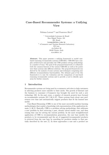
InstallationShould the owner decide not to use the provided brackets, mounting of the ITC-FS must incorporate all of thefollowing dimensional safeguards (Refer to Figure 2):The ITC-FS employs a SSR (Solid State Relay)as a means to switch the heating load power.Inherently, SSR’s produce heat when operating. Heat is dissipated at the rear of the ITCFS through a heat sink. By design, the ITC-FSmust be mounted in a vertical orientation inorder to allow the heat sink to properly dissipate the heat from the controller. See Figure 1.1. Maintain a minimum of 1.5” (3.8 cm) of free air spaceon either side of the heat sink (K)2. Maintain a minimum of 1.8” (4.6 cm) of free air spacedirectly behind the heat sink (C)3. Zero air flow restriction above and below the heatsink.4. The mounting surface, customer mounting bracketand fasteners must be of suitable structural designto support four times the weight of the equipment.The ITC-FS is shipped with a pair of stainless steelmounting brackets. These brackets were specificallydesigned to allow sufficient airflow in and around theheat sink. The air flow above or below this heat sinkmust in no way become restricted. See Figure 1.To maintain UL compliance, the heat sink must beinspected every season to confirm that no debris orobjects are in contact with the heat sink. All debrismust be removed from the heat sink fins. High pressureblasts of clean, dry air or other means which will notdamage the fins are to be used to dislodge all debrisfrom the fins.Violating any of the heat sink clearance dimensions or if the equipment is used or mounted ina manner not specified by Chromalox, the protection provided may be impaired. This couldresult in equipment damage, personal injury orboth.1.8”1.8”MountingBracketsHeat SinkFrontHeat SinkMounting Surface1.5”1.5”FrontRight Side Viewof ITC ControllerTop View of ITCControllerFigure 1Figure 2Mounting Surface ConsiderationsFastenersThe preferred materials of the mounting surface include metals, concrete or wood products. If the ITC-FSis to be mounted outdoors, then the metals shall havecorrosion resistant properties and the wood productsshall be treated for outdoor use. If the mounting surface is plaster (drywall), it shall be of the following minimum construction: 1/2”, /-1/16” (10 mm, /-2mm) inthickness and supported by nominal 2” x 4” (50mmx 100mm, /-10 mm) studs that are on 16”, /- 1/2”(400mm, /- 10mm) centers. See Dimensions sectionfor wall mount layout and hole location. Mounting shallbe performed by experienced professionals.The fasteners shall be of 300 series (304 or 316) stainless steel and they shall be a #8 or #10 (or metric equivalent) bolt or screw configuration. If anchors are to beused, ensure that they match the fastener specification.Improper mounting may cause an unsafe condition resulting in equipment damage or failurewhich could cause personal injury.7
InstallationConduit SpacingsThe maximum number of conduit entries on the bottomof the enclosure (shaded in red) is 3 and the maximumnumber of conduit entries on the side of the enclosure (shaded in red) is 3. Ensure 3/4” conduits have a1-13/16” spacing from center to center and 1/2” conduits have a 1-9/16” spacing from center to center.Ensure 3/4” conduit fittings have a 1-13/16” spacingfrom nearest obstruction and a 1/2” conduit fitting hasa 1-9/16” spacing from the nearest obstruction.The conduit hub must be connected to theconduit before connection to the enclosure ismade.Mounting Surface ConsiderationsConduit Installation Conduit entries may be made inthe red shaded area of the enclosure shown above. Ifpossible conduit entries should be made on the bottomof the enclosure to reduce the possibility of water entryor leakage. Conduit entries must be drilled/ punchedfollowing the enclosure manufacturers’ recommendations. Use fittings suitable for the enclosure type andinstall such that the completed installation remains waterproof. For nonmetallic enclosures, grounding hubsand conductors must be installed in accordance withArticle 501-4(b) of the National Electrical Code and PartI of the Canadian Electrical Code.8
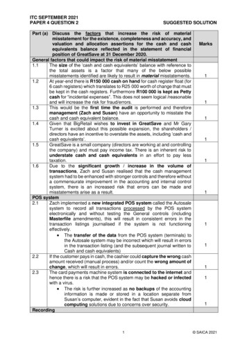
Operating the ITC-FSHMI (Human – Machine Interface)There are three areas on the front panel of the ITC-FSin which the User may visually receive information orprovide input to the controller:1. LED status indication for Power,Load & Alarm for each circuit2. Hi Resolution TFT displays the parameter settings,alarm type, mode of operation, current loaddemand, program menu screenand menu selection items3. Capacitive touch keypadMain WindowIn normal operating mode, the main window screen onthe ITC-FS displays the circuit number, set point temperature, process temperature, current load demand,soft start status, mode of operation, output % and alarmtype for each active circuit.Below is the Main Window for a 2 Circuit ITC-FS.Circuit NumberSet Point TemperatureMaintain Temperature4040Current Load,Bar Graph & ValueMode of Operation& Output % per CircuitSoft Start Status9Auto Mode Type(PID or On/Off)
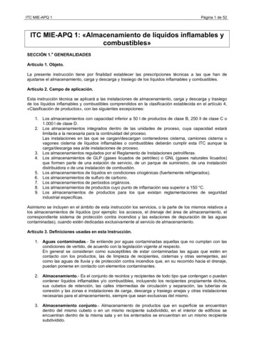
Navigating the ITC-FSVisually, here is how one navigates through the ITC-FS Menus & Parameters:Security Level 3Security Level 2Security Level 1Mode1. Main WindowNo2. LoginLogged?NoYesYesCorrect?3. Temperature Menu Mode4. Current MenuModeMode5. Control Menu6. Comms MenuMode7. System MenuTemp Setpoint 1Lo Current Alarm 1Auto Control Mode 1Auto Control Mode 2Baud RateFirmware VersionLo Temp Alarm 1Hi Current Alarm1Auto/Man/Off 1Auto/Man/Off 2ParityButton SoundHi Temp Alarm 1GFEP Setpoint 1Deadband 1Deadband 2Modbus IDUnitsTemp Setpoint 2GFEP Alarm/Trip 1Autotune 1Autotune 2IP AddressTemp. Sensing 1Lo Temp Alarm 2Lo Current Alarm 2Prop. Band 1Prop. Band 2DHCPTemp. Sensing 2Hi Temp Alarm 2Hi Current Alarm 2Integral 1Integral 2Failed SensorOutput 1GFEP Setpoint 2Rate 1Rate 2Failed SensorOutput 2GFEP Alarm/Trip 2Soft Start 1Soft Start 2Manual Offset 1Manual Offset 2Password Level 2Alarm StateDashed Parameter Ovals appear on 2-Circuit Units OnlyDashed, Angled Connector - continuation path for 2-Circuit Units OnlyModePassword Level 1Password Level 3Curved Double Arrow - continuation path for 1-Circuit Units OnlyGFEP Alarm/Trip 2ModeRestore to DefaultMode arrow represents pressing the MODE Keywhile the operator is at the last available menu screenwithin the current security level.The horizontal security level bars, which are above theITC-FS Menu & Parameter navigation map, illustrate theavailable menus within that security level. The Main Winbutton is selecteddow is presented when the10
The KeypadThe function of each key is as follows:There are five capacitive touch keys or buttons on thefront panel. The keypad allows the user to select orchange parameters & settings, clear alarms and navigatethroughout the ITC-FS programming areas. See Figure3 shown below:MODEUPDOWNENTERRESETKEYFUNCTIONMODEAllows the user to Navigate betweenMenus & Main WindowUP1. Within a Menu, Scroll UP to next Parameter or Setting within that Menu2. When viewing an adjustable parameteror setting, increments that parameterUP to the next available value. For aquick scroll, push and hold the key.DOWN1. Within a Menu, Scroll DOWN to nextParameter or Setting within that Menu2. When viewing an adjustable parameteror setting, increments that parameterDOWN to the next available value. For aquick scroll, push and hold the key.Figure 31. To accept a parameter or setting thathas been entered or changed.2. Press to accept the change when viewENTERing an adjustable parameter or setting.3. When in LOGIN Screen, press to advance to next security digit.RESETResets or clears all alarmsProgramming the ITC-FSThe ITC-FS is pre-programmed with default parametersand settings that allow it to function “right out of thebox”. To change any of the parameters or settings on theITC-FS, you must access the appropriate menu(s): Temperature Menu, Current Menu, Control Menu, Comms(communications) Menu or System Menu.MODEUPTo access any of these menus, press thebutton on the keypad. You will be presented with theLogin screen:Press ENTER to advance to the nextdigit.DOWNRESET11
Security LevelsYou must first enter a passcode that is aligned with themenu that you wish to access. In most cases, limitedaccess to certain programming areas is desired. Themost frequently used parameter settings have the lowest level of security. Invalid passcodes will not be accepted and you will be returned to the LOGIN Screen.You will be returned to the main screen if no buttonsare depressed within a 30 second time frame.Passcodes may be reprogrammed within the SystemsMenu. These codes should be kept in a secure place.Initial factory set passcodes for the Security levels below are:SecurityAvailableLevel PasscodeProgramming Menus10011Temperature Menu OnlyTemperature & Current20034Menus OnlyTemperature, Current, Control,30063Comms & System MenusThe Temperature MenuSecurity Levels 1, 2 & 33. Temperature MenuThe Temperature Menu provides access to the Temperature based parameters: Temperature Setpoint,Low Temperature Alarm & High Temperature Alarm forCircuits 1 and 2 (when available).12TemperatureSetpointProcess Temperature VariableLowTemperatureAlarmLower limit of the Process TemperatureVariable at which the system goes intoalarm state. This alarm may be turnedOFF by going one increment beyondthe Lowest setting.HighTemperatureAlarmUpper limit of the Process TemperatureVariable at which the system goes intoalarm state. This alarm may be turnedOFF by going one increment beyondthe Highest setting.
The Current Menu4. Current MenuSecurity Levels 2 & 3LowCurrentAlarmLower limit of the Load Current Variable atwhich the system goes into alarm state.This alarm may be turned OFF by goingone increment beyond the Lowest setting.HighCurrentAlarmUpper limit of the Load Current Variable atwhich the system goes into alarm state.This alarm may be turned OFF by goingone increment beyond the Highest setting.GFEPSetpointUpper limit of the Ground Fault EquipmentProtection Variable at which the systemgoes into alarm state. NOTE: to determineHight current circuit value. Referenceinstallation manual.GFEPAlarm/TripAction taken by controller when the GFEPSetpoint alarm condition is achieved.The options are:Output remains atselected output %.1. Alarm Only,Alarm clears whenNon-Latching sensed GFEP current is 5mA GFEPsetpointOutput goes to 0%(off) while in alarm2. Alarm & Trip, state. Alarm clearsNon-Latching when sensed GFEPcurrent is 5mA GFEPsetpointThe Current Menu provides access to the current andGFEP based parameters: Low Current Alarm, HighCurrent Alarm, GFEP Setpoint & GFEP Alarm/Trip forCircuits 1 and 2 (when available).NOTE: When operating a 2-circuit ITC, if circuit 2 (topboard) is not being used, set the GFEP setpoint 2 setting to “OFF”133. Alarm Only,LatchingOutput remains atselected output %.Alarm condition mayonly be cleared with amanual reset.4. Alarm & Trip,LatchingOutput goes to 0%(Off) while in alarmstate. Alarm conditionmay only be clearedwith a manual reset.
The Control MenuSecurity Level 3The Control Menu provides access to the types of Automatic Control, Mode of Operation, the parameters whichinfluence the control algorithms and the Soft Start function: Auto Control Mode, Auto/Manual/Off Control, Deadband, Autotune, Proportional Band, Integral, Rate (Derivative), Soft Start function and Manual Offset.5. Control MenuAuto Control ModeWhen the ITC-FS is in AUTO Mode (see AUTO/MANUAL/Off parameter), the choice of Automatic Controlis either PID or ON/OFF Mode.Determines the type of Control Operation: Automatic, Manual or Off.Auto/Manual/OffAutomatic Control: Select Auto. This allows On/Off control.(Mode of Opera- Manual Control: Select 1 – 100. This is the % power output.tion)Off: Select 0. This equates to 0% output, which turns off that circuit.NOTE: The Soft Start function will only engage when the ITC-FS is in AUTO ModeThe ITC-FS Autotune function establishes the individual P, I & D (Proportional Band, Integral & Derivative) controlmodes. These modes help to bring the process variable to the setpoint temperature as quickly as possible.AutotuneIn order to properly calculate the P, I & D modes, the Autotune program requires a 25 degree rise in sensedtemperature after initiating the program. If within 30 minutes the temperature will not reach its setpoint, theAutotune algorithm will be canceled and old PID values will be used.Once the Autotune feature is activated, you must not change the menu page until the Autotune algorithm iscompleted. Changing the page will cause the Autotune algorithm to shut down.The Autotune function is a one-time algorithm set up of the P, I & D control modes. Should your processvariables change significantly, it is suggested to that the Autotune feature be turned off and then reinitiated.Active ONLY when the ITC-FS is in Auto Mode & under On/Off ControlDeadbandThe temperature range equally divided above & below the temperature set point, where the controllerwill not take corrective action.Example: A setting of “10” for the deadband will result in a deadband that is 5 degrees above and belowthe temperature setpoint.Proportional Band, Active ONLY when the ITC-FS is in Auto Mode & under PID ControlPThe Proportional Band (P), the Integral (I) & Derivative (D) are modes of control that work in union to bringthe process variable to setpoint as smoothly and quickly as possible. The P, I & D will be automaticallyIntegral, Iestablished during the Autotune procedure (see above).(Automatic Reset)Additionally, the P, I & D may all be manually established by the user. Great care should be taken whenDerivative, D (Rate) manually establishing the P, I & D.Proportional Band: The temperature range above and below the temperature set point.Soft StartWill only be available while the Mode of Operation is set to AUTO.Options are On or Off.Only available while the Mode of Operation is set to AUTO & under PID ControlThe Manual Offset may be used in conjunction with the PID variables to assist in Tuning the controller.Typically, heat trace applications will not require any Manual Offset adjustment.Manual OffsetManual Offset allows the user to preprogram the approximate power output (%) requirement at the setpoint. This has been proven to reduce the time needed to align the process temperature with the setpointtemperature. As a rule of thumb, relatively light heating loads will require smaller Manual Offset values.The Manual Offset is a percentage output wit
The intelliTRACETM ITC-FS1 and ITC-FS2 provides the user with an easy to navigate menu system, continu-ous critical parameter monitoring, application flexibility and equip-ment safety precautions. The ITC-FS is an ideal solution for Freeze Protection of Fire Suppression Systems. intelliTRACETM ITC-FS Features: 1 & 2 Circuit Models