Transcription
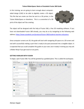
Tulane MakerSpace: Basics of Autodesk Fusion 360 GuideIn this training, we are going to learn enough about computeraided design (CAD) to be able to digitally create a 3D object.This file that we create can then be sent to a 3D printer, in theTulane MakerSpace or elsewhere. This is a screenshot of a 3Dprint of the object we’ll be creating:The object will be designed with the help of Fusion 360, a free 3D modeling software. If youhave not downloaded Fusion 360 already, you may do so by navigating to the following webaddress: nts-teachers-educatorsSince computer screens are 2D, the guide will start with navigating 3D space on a 2D screen andend with successfully making a part that is ready to be post-processed into a tangible object. Itis expected that you could complete this guide on your own, but in today’s training you may aska Maker Ninja if you get stuck on any parts.GETTING FAMILIAR WITH FUSIONTo begin, open Fusion 360. You will be greeted by a gridded plane. This is called the workspace.Afsheen Sajjadi1
On the left, there is a sidebar called the Data Panel which contains your project library, whereyou can organize your different projects by folder. This sidebar also contains several additionalsamples and tutorials. At the upper left corner of the Data Panel, your name should be shown.If the sidebar isn’t shown, but the gridded plane is visible, click on theData Panel button, which looks like a grid of 9 squares. This button isfound in the upper left corner of the program.Click on the bluebutton to create anew folder. Name this folder “MakerSpace Guide”for this walk-through. Double click on the yournewly created project folder, visible in the sidebar,to show the empty file directory. Here you canupload any files that may be relevant to the projectto keep organized.Afsheen Sajjadi2
It is important to note that you can actively shareyour project for group collaboration efforts byclicking the “People” tab next to “Data”. Hereyou can invite the emails associated with yourgroup member’s Fusion 360 accounts. Let’s closeout the project sidebar/data panel so we can usethe entire screen for viewing the model. Click onthe data panel buttonin the upper left ofyour workspace to hide the data panel.Next, click on the file buttonjustto the right of the data panel buttonin the upper left corner of the program.Select on save to bring up a popup. Savethe current file as MakerCoin, makingsurethatthelocationshowsMakerSpace Guide.This is the project we just created. All changes made to the model are actively saved to thecloud if you are connected to the internet. Otherwise, the changes to the model will upload tothe cloud next time that you open Fusion 360 when you are connected to the internet.Before we get started with our model, let’s make sure our system of units is what we desire.For this model, we will be working in imperial (English) units, with our unit of measure beinginches. Why inches? Because that is what most machinists in the America and their equipmentuse and it makes compatibility easier with commonly sold parts like screws.Afsheen Sajjadi3
To verify our system of unit, look under the floating browsermenu in the upper left corner. There will be an option fordocument settings. Click on the arrow to the left of this optionto expand its menu.The Units option should now be shown along with the currentmeasurement system for length. In my case, this says “mm,” butyour units may be different. We want to change this to say “in” so that inches are our base unitfor our measurement.If you hover over the words “Units: mm”, abuttonwill appear to the right of the word.Click on this buttonand a window should appearcalled “Change Active Units”. Click the dropdownmenu next to unit type, and select “Inch”. Click ok,and your units will now be set to inches.Now let’s get oriented with moving around in the workspace. Use your mouse to zoom in andout by scrolling. If you have a laptop with a trackpad, you can use pinch to zoom.You have several options to change the view. The first option is to use the free orbit toollocated in the Navigation Bar at the bottom of your screen.Clickon the free orbit tool and then click and drag anywhere on the gridded workspace to observethe changes in the view. The pan toolwill allow you to basically slide your view from left toright as well as up and down. The pan toolmirrors the motion of a person when they turntheir head on their neck from left to right. The second option you may use to change your viewAfsheen Sajjadi4
requires the use of an external mouse with scroll wheel and middle mouse button. This is theoption that most people prefer. Click and hold the middle mouse button while dragging to panyour view of the gridded work-space. You can also pivot the view if you hold the Shift key whileusing the middle mouse button. The ViewCube in the upper right corner allows you to quicklychange your perspective to certain views, as well as freely manipulate your view. In the upperright corner, hover over the ViewCube and click the homebutton to reset your view of the3D workspace. To see other perspectives, left- click and drag along the faces, edges, or cornersof the ViewCube to center your view along that plane. By clicking and dragging on the box, youcan pivot your view about the origin (the dot in the middle) which indicates the x, y, and zcoordinates to be zero.STARTING A SKETCHNow that we can move around, let’s start building our model.First, we’ll create a cylinder with a height of ½ inch and adiameter of 2 and ½ inches. Click on the Create Sketch buttonon the leftmost part of the SKETCH tab on the upper toolbar.A sketch is a 2-dimensional object. Fusion 360 can place our 2dimensional object in any of three planes, but we need to tell itwhich plane to work in. The three squares representing the 3different default sketch planes should show up in the middle of thescreen. Click on the lowermost sketch plane. This means we willstart building our model from bottom to top. The view shouldautomatically change to an overhead view typically denoted as “top view”.Afsheen Sajjadi5
Next click on the SKETCH drop down menu. As youcan see there are a lot of options to draw yourdesign. Hover over the Circle option and click on theCenter Diameter Circle button. Any circle type willwork, but for our purposes, we want our model to bebuilt centered around the origin point. The otheroptions are primarily for designs where we arecreating circles in reference to other shapes and objects.Next move your cursor to the center point. Click and drag yourmouse outward and see the circle expand. You also will see ahighlighted box with a diameter measurement appear. To finishthe circle, click anywhere on the screen to generate the circle. Wewant to dimension the circle to get the specific diameter we desire.Dimensioning the circle makes the diameter a parameter that caneasily be adjusted in the future.Click on the SKETCH drop down menu,and at the bottom, click on SketchDimension. Next, click on circle’s blueborder to get the dimension and thenclick outside of the circle to verify the dimension. This will allowyou to type a diameter of 2.5 inches and hit enter to set it. Please note that you can type simplemath in this box to get half of a dimension or adding 3 inches, which can be useful in somecases.Go back to perspective view by clicking on the Home button. This isfound by hoveringover the ViewCube in the upper right corner.Afsheen Sajjadi6
EXTRUDING A SKETCHNext, we will take our 2D sketch and turn it into a 3D model byextruding it. When you look at the end of an open tube oftoothpaste, you see a 2D circle. By squeezing the tube, youextrude the toothpaste into a 3D cylinder. Click on the Create menu and Extrude tool will beactivated. Then click anywhere in the circle to select it. An arrow will appear along with theextrude menu.The distance option in the extrude menu allows forprecise control over how tall a structure is createdfrom the 2D sketch. Instead, here we will click onthe arrow and drag the mouse upwards to extrudethe model until the box on the right reads 0.25 inches. Hit enter to finish theextrusion. Your circle is now a shaded gray cylinder.Notice how at the bottom of the screen there is a row of icons that acts as a timeline. You canmove the progress bar from the right to go back along your design and hide features that youmade. If something is built atop another, you can also delete features that you may no longerdesire. Right‐clicking on a feature allows you to change values and make various edits. Forexample, if you want to increase the height of the base cylinder, then right click on the firstextrude feature to change it. The play pause forward backward buttons allow you to watch howyour model was built up, step by step.Afsheen Sajjadi7
ADDING A FILLETNow that we have a 3D object, we will use this cylinder as a base aroundwhich we will build up the rest of our 3D model. The edges of the cylinderare sharp we will round off these sharp edges using fillets to get more of anaesthetically pleasing coin. A fillet (pronounced “fill-it”) is arounded edge. To begin, click on the fillet tool under the modifymenu which will open the FILLET window.Click on the upper and lower edges of the cylinder, so theedges turn blue. Once selected, type 0.1 to set the fillet radius to 0.1 inches. The number ofedges and the size of the edge radius will appear in the FILLET window. For the purposes of thistutorial, we don’t need to modify the rest of the options available in the FILLET window. Clickto finish adding the fillet.Afsheen Sajjadi8
SKETCHING A TRAPEZOIDNow that we have a smooth coin, let’s add some uniquefeatures. First, let’s create notches around the coin to make itlook more like a gear.To begin, we need to sketch a trapezoid on the top of the coinwith which we may cut. We need to select a surface from whichwe can continue to manipulate our model. Click on the top faceof our cylinder to select it. We will use the line tool to draw andconnect 4 lines to make a trapezoid.With the top face of thecylinder still selected, click theLine tool in the SKETCH section. The view will changeto the top face. Scroll out slightly with your mouseto have the area around the top face in view. Clickjust outside of the cylinder near the top face to setyour first point. The point should be in that generalarea, but we will use a tool later to more accuratelyposition it.Nowwithyourfirstpointchosen, horizontally move yourmouse to the right past thevertical green line and select apoint. The last two points of our trapezoid will be inside thecylinder. Once you create those points, click on our first point tocomplete the trapezoid. The interior of the trapezoid yellow.Afsheen Sajjadi9
Now that we have a trapezoid, let’s make it more symmetrical byadding dimensioned angles. We will use the Sketch Dimension toolto accomplish this. Click on the SKETCH button to open the SKETCHdrop-down menu. Near the bottom of the menu, clickon Sketch Dimension. Next, click on the top line of thetrapezoid and then click the right side of the trapezoid.An arbitrary angle dimension will appear. Click on theinside of the trapezoid so you can type the angle. Feelfree to choose any angle you want, but for the purposesof this tutorial, I will choose 75 degrees. Repeat thisprocedure for the angle between the top line of thetrapezoid and the left side of the trapezoid.MULTIPLYING TRAPEZOIDSTo get the gear aesthetic we are looking for, we needto make 7 more of these trapezoids. Luckily, we don’thave to make the rest of these by hand. We can use theCircular Pattern tool in the SKETCH menu.Click on the SKETCH button toopen the SKETCH drop-downmenu. Near the bottom of themenu, click on Circular Pattern. The CIRCULAR PATTERN window willopen. Starting from outside the trapezoid, click and drag over thewhole trapezoid to select it. All the vertices and edges of the trapezoidshould become highlighted. Then next to the Center Point text in the CIRCULAR PATTERNwindow, click on Select. Now, click on the center of the cylinderto select it. This will make the trapezoid evenly pattern around the cylinder.Afsheen Sajjadi10
Finally, for the Quantity in the CIRCULAR PATTERN window, type 8 in the box, so we will have atotal of 8 trapezoids distributed evenly around the cylinder.Clickto finish the circular pattern.CUTTING THE TRAPEZOIDSGreat, now we have a bunch of trapezoid sketches, but we need to cut themout of the coin to get the gear aesthetic we want. To begin, let’s click on the Extrude tool in theCREATE section of the toolbar. The EXTRUDE window will pop up, prompting you to select thesketches to cut or extrude. Click on each of the trapezoids. Notice when you click the trapezoid,it is split into 2 regions. This is because the Extrude tool is also considering the circle around thecylinder created by the fillet to be part of the sketch. Click on both regions of each trapezoid.Once you select all aspects of the trapezoids, it will prompt you to set an extrude amount. Sincewe want to cut, type -0.25 in the box.Afsheen Sajjadi. Clickto finish the cut.11
If you make a mistake, you can use the undo button in theupper left corner. This will undo features, sketches, anddimension changes, but not necessarily an accidental edge selection. In those instances, if youare in the fillet or chamfer menu, you can just click the edge again to deselect it.ENGRAVING YOUR INITIALSSelect the top face of our model. Click on the SKETCH button to open the SKETCH drop-downmenu. Near the middle of the menu, click on Text. Click near the center of the cylinder, but notthe exact center. The TEXT window will open. Type your initials in the first box. Change theheight to 0.5 inches. Additionally, bold your text by clicking on the B icon. I set my angle to 180so it would be right side up on my screen, but it’s not critical. Clickto finish writing thetext. You can proceed to move the text to better center it by clicking and dragging the textaround.Click on the Extrude tool and select your text. Type -0.10toengrave the text into the model. Since this value is less than our model height, itwill only be inset into the model. Go back to home view by clicking on the Home button.Afsheen Sajjadi12
You now have a completed part ready for simulation,animation, or just presentation. To export yourparts as a 3D printable file, click on the 3D printtool in the MAKE section of the toolbar. The 3DPRINT window will open. Click on your model toselect it for export.This will save your part as a mesh file which iscomposed of many triangles as you can see byclicking Preview Mesh. For our purposes thedefault settings are fine. Uncheck Send to 3DPrint Utility under the Output tab if it ischecked. We do not want to send the file toanother program, rather, we want to save it as a 3D printable file. Click, and a windowwill pop up asking you where to save the file.Using this save window, navigate tothe location that you want to save it.In my case, I will save it to a foldercalled 3D Models in My Documentsto keep my 3D printable files fromFusion 360 organized. Once you havepicked a location, click ok and the 3Dprintable file should immediatelysave to the location you chose. Notice that 3D printable files have a file extension of .STL similarto how Microsoft Word documents use a file extension of .docx. This .STL file can be now bemoved to a USB and imported into Cura in the MakerSpace to prepare it for 3D printing.Afsheen Sajjadi13
Tulane MakerSpace: Basics of Autodesk Fusion 360 Guide Afsheen Sajjadi 1 . In this training, we are going to learn enough about computer-aided design (CAD) to be able to digitally create a 3D object. This file that we create can then be sent to a 3D printer, in the Tulane MakerSpace or elsewhere. This is a of a screenshot3D