Transcription
EE133 – Winter 2002Cookbook Filter GuideWelcome to the Cookbook Filter Guide!Don’t have enough time to spice out that perfect filter before Aunt Thelma comes down for dinner?Well this handout is for you! The following pages detail a fast set of steps towards the design andcreation of passive filters for practical use in communications and signal processing. Amaze yourfriends and neighbors as you do twice the amount of work in half the time!Here’s a brief overview of the steps: Specify your filter type Implement a low-pass version of your filter Transform it to what you really want (high-pass, bandpass, bandstop) Simulate and Iterate Step 1: What Filter Do I Want?This is where you have to do most of your thinking. It’s no good to cook up a nice steak dinnerif Auntie Thelma turned vegetarian last year. Here are the specifications that are most oftenquoted with filters:Filter Type (Low-Pass, High-Pass, Band-Pass, Band-Stop)Center frequency (rad/s or Hz)Bandwidth (rad/s or Hz)Cut-off/Roll-off rate (dB)Minimum Attenuation Required in StopbandInput Impedance (ohms)Output Impedance (ohms)Overshoot in Step ResponseRinging in Step ResponseWe will be creating filters through a method known as the insertion loss method. Insertion Loss,or the Power Loss Ratio PLR.is defined as:PowerSource1PLR 2PowerDelivered 1 Γ(ω )Γ is our famliar reflection coefficient. It turns out that this is expressible in the following form of :M(ω 2 )PLR 1 N(ω 2)Where M and N are two real polynomials. Which simply means that we can define an arbitrary filterresponse and use this formula to match it to real components, thus allowing us to make it physicallyrealizable. There are several standard filter responses, each with their own advanatages and drawbacksStandard Filter Responses Butterworth (AKA Maximally Flat or Binomial) FiltersButterworth filters are general purpose filters. Another common name for them isa maximally flat filter, which refers to the relatively flat magnitude response in the passband. Attenuation is –3dB at the design cutoff frequency with a –20dB/decade roll off perpole above the cutoff frequency.1
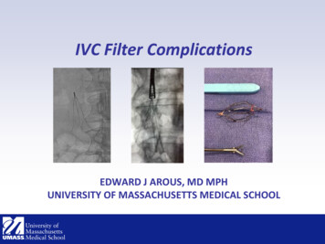
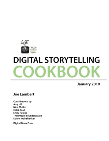
EE133 – Winter 2002Cookbook Filter Guide Chebyshev (AKA equal ripple magnitude) FilterChebyshev filters have a steeper attenuation above the cutoff frequency, but at theexpense of amplitude “ripples” in the pass-band. For a given number of poles, a steepercutoff can be achieved by allowing more pass-band ripple. The cutoff frequency isdefined at the point at which the response falls below the ripple band of the pass-band. Bessel (AKA Linear Phase or Maximally Flat Time Delay) FiltersSometimes a design requires a filter to have a linear phase in order to avoid signaldistortion. In general a good phase output (i.e. linear) always comes at the expense of agood magnitude response (i.e. fast attenuation). Elliptic FiltersFor the previous filters, as the frequency gets progressively further from thecenter frequency the attenuation increases. Sometimes a design only requires a minimumattenuation in the stop-band. This relaxes some constraints on the response which allowa better cutoff rate. However, this filter has ripples in both the passband and stop-band. Step 2: Prototyping a Low-Pass DesignHaving finally specified your filter, it’s time to prototype a low-pass version of your filter.Although it seems counterintuitive to spend time on a filter that doesn’t even necessarily have the passband/stop-band characteristics of your desired filter, it will become apparent that there is relationbetween the values derived for a low-pass situation and the other filter types.As an example we will design a low-pass filter for a source impedance of 50 ohm, a cut-off frequency of1MHz and which requires a minimum attenuation of 40dB at 10MHz.Determine the type of filter and N, the order of the filter:First we have to determine which of the filter types we want to use. Do we care abouthaving linear phase? Or is maxmium cut-off attenuation the critical factor? Once that’sbeen done, we can then determine the order of the filter necessary to fit the requiredattenuation spec. Usually, we refer to a graph like the one below showing the attenuationcharacteristics for various N versus normalized frequency for a particular filter type.In this case, we decide that a flat ma gnitude response in the most appropriate. So then welook at the graph.The definition of normalized frequency is:wf norm 1wcwe find that wc 1MHz wo 10MHz which means the normalized frequency is 9. Lookingon the graph we see that N 2 will easily satisfy our requirements for 40dB of attenuation.2
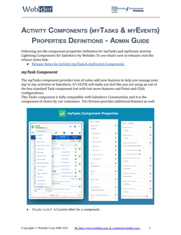
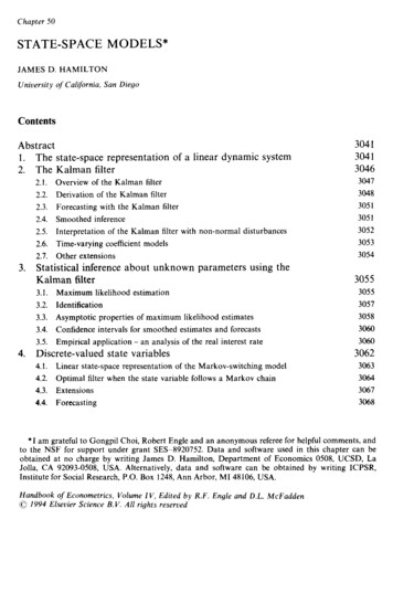
EE133 – Winter 2002Cookbook Filter GuideDesign a Normalized Low-Pass Filter using a Table:Once that is done, we can now design a second order prototype filter for a sourceimpedance of 1 ohm, a cut-off frequency of 1 rad/sec. As shown in the figure below, we use oneof two equivalent ladder circuits. Note the way the element values are numbered, with g0 at thegenerator to gN 1 at the load.How to read this chart:g o generator resistanceor agenerator conductancegk inductance for series inductorsor acapacitance for shunt capacitorsg N 1 load resistance if g N is a shunt Cor aload conductance if g N is a series LA key point is that the componentsalternate between shunt and series.Note that during out prototyping,inductors are always series, capacitorsare always shunt. The only differenceis whether or not the first element isseries or shunt.3
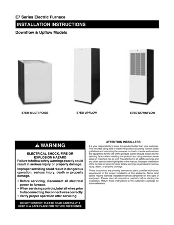
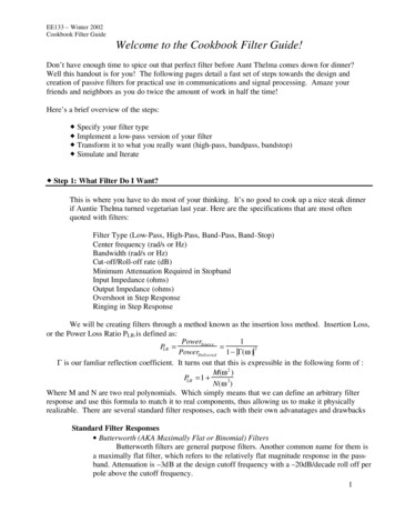
EE133 – Winter 2002Cookbook Filter GuideTo design a filter of a particular response (i.e. Butterworth, or Bessel) there is a unique ratio ofcomponents to be used. These ratios are usually kept is handy tables like the one below.Element Values for Butterworth (Maximally Flat) Low-Pass Filter Prototypes(go 1,wc 1,N 1 to .34730.90801.00000.31291.0000For a second order, we see that g1 and g2 must both equal 1.4142 and g3 , the load, must equal the go , thesource resistance. So the following circuit will get us a low pass filter centered about 1 rad/sec. Step 3: Transforming the Low-Pass Prototype to the Desired FilterAll we have to do now is transform the prototype into something we can really use. The tables assume aset impedance Rs Rl 1 ohm (except for Chebyshev filters, where the source and load resistance differby a set amount). In addition, the filter’s cutoff frequency is 1 rad/sec, a fairly useless value in general.So we need to scale for impedance and frequency.Let’s start with impedance scaling. To take this into account, we need to multiply the impedances of theprototype by the desired Rs. Since the prototype input impedance is always 1 ohm, we can simplymultiply by the ratio. Rl naturally needs to scale proportionally, while all capacitors need to be dividedby Rs and all inductors need to be multiplied by Rs.Now that we have these original values, we need to swap components in order to obtain the correct filtertype. Below are the substitutions.4
EE133 – Winter 2002Cookbook Filter Guide w1 w2is your friendw0 is a term to describe the sharpness of the filter. If you look at it really hard, you’ll see it’s actually theinverse of Q. In filter design the center frequency is not chosen as the arithmetic mean, but thegeometric mean. In other words:w1 w22wo w1 w2wo This allows for the math to work out such that straight substitutions are allowable. What this means isthat often times, you’ll pick your bandwidth and just go for a center frequency in that area. Of course,you could work out the math to get exactly the center frequency you want, but sometimes, you reallydon’t want to think that hard about a minor filter.With that all said here are the transformations. The formulas on the next page were derived bycomparing the frequency dependent impedances and mapping the cutoff frequency to differentsituations. In each one, the Lk or Ck from your prototype is coverted into a new Lk ’ or Ck ’. A derivationof these formulas can by found in Posner’s Microwave Transmission. NOTE: These formulasALREADY take into account the scaling for impedances.5
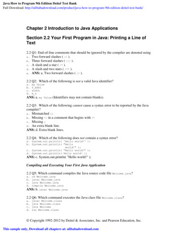
EE133 – Winter 2002Cookbook Filter GuideTRANSFORMATION TABLELow-PassSimple impedance and frequency scaling.1L' RLk w s kc1 CkC' k w Rc sHigh-PassNote the swapping of capacitors and inductors:11C' k w R Lc s k1 RsL' k w Cc kBandpass1 Rs Lkwo 1 wo RsL kL'Lk Series inductor Lk transforms to a series LC circuit defined by:C'Lk1wo1 woL'Ck Shunt capacitor Ck transforms to a parallel LC circuit with element values:C'CkRs CkCkRs Bandstop1 R Lwo s k1 1C'Lk wo Rs L k1 RsL'Ck wo Ck1 CkC'Ck wo RsL'Lk Series inductor Lk transforms to a parallel LC circuit defined by:Shunt capacitor Ck transforms to a series LC circuit with element values:In our case, we can see that we need to multiply our L value by Rs/wc and our C value by 1/wc Rs.L 11.25uH and C 4.50nF. Now we test this in HSPICE or Matlab and see if our response is goodenough for our purposes. If not, we iterate, making educated tweaks. Note that we’ve mainly designedfor the frequency domain in this methodology, which is fairly straightforward. Time-domaincharacterstics, such as ringing, or overshoot, are often equally important but the methods for dealingwith them are completely different. But that’s for another handout to cover 6
EE133 – Winter 2002Cookbook Filter .51760.44500.39020.34730.3129Element Values for Butterworth (Maximally Flat) Low-Pass Filter Prototypes(go 1,wc 1,N 1 to .0000N12345678910Element Values for Bessel (Maximally Flat Time Delay) Low-Pass Filter Prototypes (go 1,wc 1,N 1 to .05570.01871.0000N12345678910Element Values for Chebyshev (Equal-Ripple) Low-Pass Filter Prototypes (go 1,wc 1,N 1 to 10)0.5dB Ripple 81180.81363.0dB Ripple 515.80953.53404.51421.00000.60915.8095Please note that these tables assume the following:2LCWhich means that your filters will have a smaller bandwidth than you usually expect if you define 3dBas your cutoff frequency. You may easy compensate this by just roughly doubling wcwc 7
Cookbook Filter Guide 1 Welcome to the Cookbook Filter Guide! . In our case, we can see that we need to multiply our L value by R s/w c and our C value by 1/w cR s. L 11.25uH and C 4.50nF. Now we test this in HSPICE or Matlab and see if our response is good enough for our purposes. If not, we iterate, making educated tweaks.